Heat Treating with Digital Solutions for the 21st Century
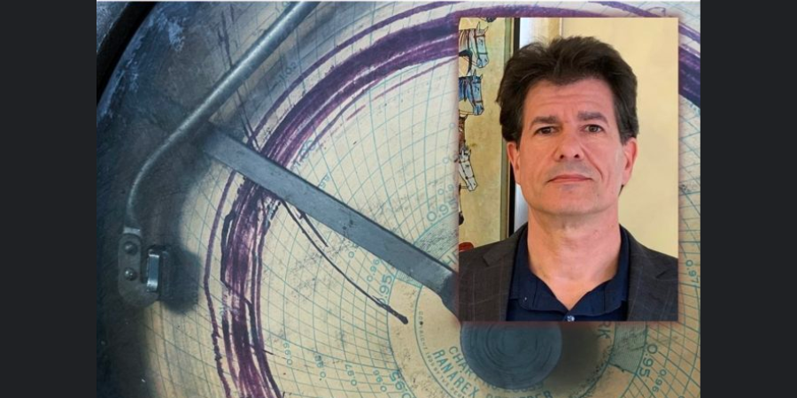
![]() On this Technical Tuesday, dive deep into this article to learn Industry 4.0 heat treating solutions to enduring problems. As author and captive heat treater Joseph Mitchell, director of Operations & Technology for The Miller Company, says, "These solutions have the capability to mitigate incessant (and costly) problems in our thermal and metal processing industry." Let's take a closer look at Industry 4.0 solutions to the problem of coil wraps "sticking" during batch annealing.
On this Technical Tuesday, dive deep into this article to learn Industry 4.0 heat treating solutions to enduring problems. As author and captive heat treater Joseph Mitchell, director of Operations & Technology for The Miller Company, says, "These solutions have the capability to mitigate incessant (and costly) problems in our thermal and metal processing industry." Let's take a closer look at Industry 4.0 solutions to the problem of coil wraps "sticking" during batch annealing.
Director of Operations & Technology
The Miller Company
As US manufacturing recovers from the ill effects of a seemingly unremitting pandemic and corollary supply chain challenges, the advance of Industry 4.0 and Industrial Internet of Things (IIOT) necessitates manufacturing industries reevaluate their business practices. For maximum profitability, business "as usual" simply will no longer suffice. Jason Ryska, global chief engineer at Ford Motor Company, suggests even production behemoths overlook the obvious:
In many production processes, data analytics provides the agility to keep up with market trends and technology advancements. An exception to this trend is automotive production, a multi-billion-dollar industry that is underutilizing data collection and underestimating the potential improvement that may come from understanding the data being collected.
This quote is from a technical article written by Ryska in which he discusses current state and offers a glimpse of future state that is gained by a manufacturer investigating potential new solutions for old process problems by applying Industry 4.0 technologies.1
Metal industry leaders may ask, to the quote above, could we replace "automotive production" with "heat treating?" I believe there is a strong argument against such an exchange of words; however, in-depth examination at the plant level indicates deficiencies exist for the heat treating industry related to acceptance of IIOT technology and application of data analytics. Where do we observe the shortcomings? Perhaps, as suggested by Ryska, in our day-to-day comfort zone: "over reliance on employee experience and interpretation vs. physical measurements."
This keen insight into the current state of automotive manufacturing can be equally applied to different manufacturing landscapes throughout U.S. industry. Reviewing a familiar heat treating problem will help to illustrate the need for and applicability of digital monitoring and data collection for decision making and future development of advanced analytics like machine learning and AI. These solutions have the capability to mitigate incessant (and costly) problems in our thermal and metal processing industry.
Heat Treat Industry
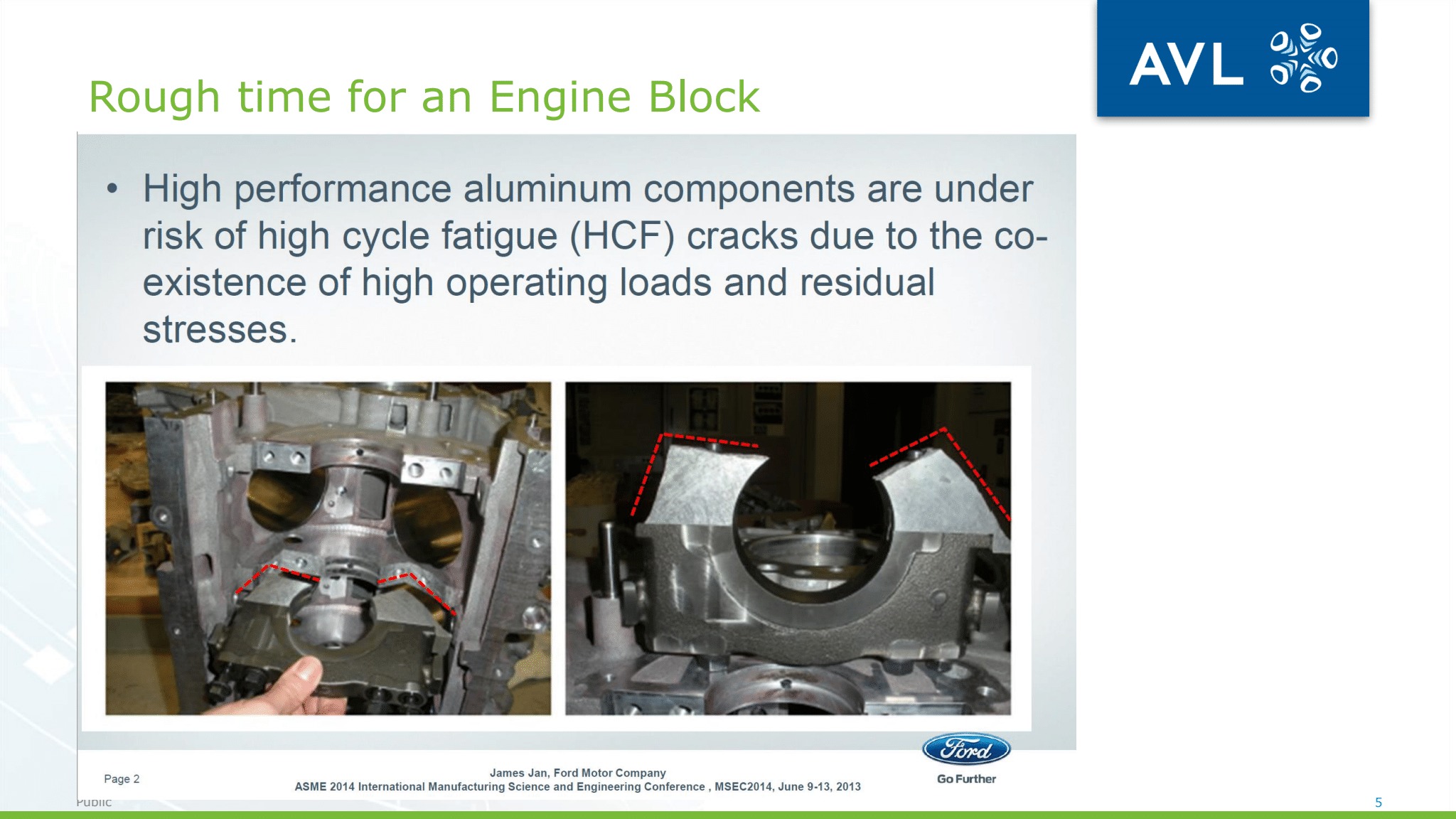
In manufacturing, the same problems often occur again and again. In the metals industry, casting and thermal processing, in conjunction with continuing operations, present daily challenges to product quality. Troublesome and costly conundrums – like residual stress, distortion, cracking/poor forming in downstream operations, and poor surface quality/coating adhesion – occur regularly, causing waste, rework, late delivery, and lost profit.
Metallurgists, engineers, and technologists all understand the frustration of untold hours devoted to researching solutions to material processing problems. Some already have well known solutions while others may randomly appear seem, after causing much angst, to disappear (sometimes not as quickly as would be preferred). Regardless of that type of problem, the time, effort, and resources put into finding the solution cannot be redeemed.
The advance of Industry 4.0 and, more specifically, IIOT into modern manufacturing can provide our metal production sector the ultimate tools for unraveling costly and recurring quality issues. We understand this progression will be gradual and very slow.
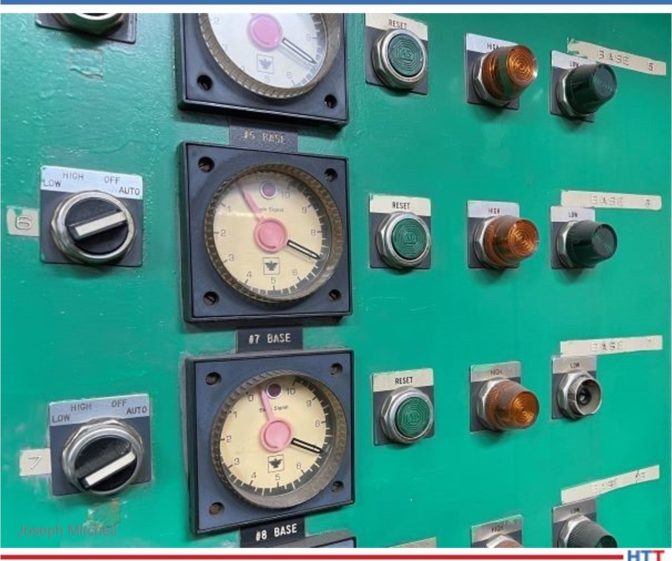
Nonetheless, implementation of digital technologies is critical for our heat treating/materials processing industry. The fact CQI-9 4th ed. requires all instrumentation and process controls be digital by June 2023 supports the emphasis placed on eliminating analog based instruments and reengineering manufacturing processes for implementation of digital data collection and, thereby, steering heat treaters (automotive suppliers and, hopefully, non-automotive industrial heat treaters) toward eventual adoption of Industry 4.0 technologies.
In this article, we review a specific quandary typically encountered during batch annealing and examine why application of digital monitoring and data collection, and eventual integration of Industry 4.0 technologies, would facilitate understanding and assist in resolving the problem.
The Problem (Define)
A report, written in 1940 by T.J. Daniels, titled "The Prevention of Sticking in Bright Annealing Sheet Steel" is interesting for many reasons, and, for purpose of this article, provides an example of an early 20th century heat treating headache which, unfortunately, is still with us in the present century.2
The report consists of two parts:
Part I - Investigation of Factors Influencing Sticking
- Pressure
- Annealing temperature
- Length of time at temperature
Part II - Prevention of Sticking
- Multiple varieties of trial suspensions tested
- Temperature, pressure, and time held constant for each test
- Trials performed 2x each
- Trials performed 3x for promising suspensions
Despite the efforts and subsequent process improvements in heat treating and manufacturing processes as discussed in Daniels' report, we find the following, equally interesting 21st century report, addressing the same subject in Hot and Cold Rolling Processes, Sticking and Scratching Problems After Batch Annealing, Including Coil Compression Stress Effects, by J.J. Bertrandie, L. Bordignon, P.D. Putz, and G. Volger.3
This 2006 report discusses the same sticking phenomenon (coil wraps adhering together after batch annealing) and expands its research into an accompanying quality problem that may occur in conjunction with or subsequent to batch annealing: material scratching. The report documents field trials and laboratory investigations.
The amount of investigative work described in this second report is noteworthy and the results provide data-backed conclusions. However, the problem addressed, potential causes studied, and solutions prescribed did not eliminate the phenomenon of sticking following batch anneal of ferrous and nonferrous coils. Fast-forward fifteen years to 2021 and the sticking phenomenon remains a topic of discussion (and source of grief) for heat treaters across continents.
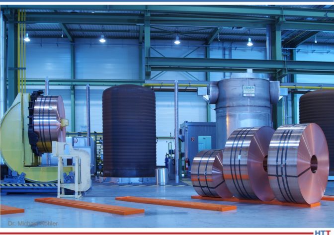
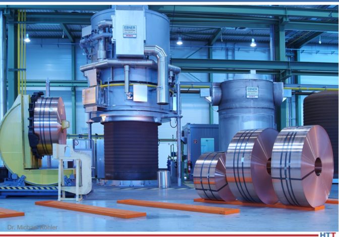
My experience with a heat treater located in the Midwest, who occasionally encountered coil wraps sticking together during batch anneal of sheet steel, resulted in experiments with anti-sticking agents applied using a spray system, as well as studies for improved control of cooling the furnace charge. The cooling temperature gradient influences contraction of outer wraps which, if pressure is excessive, may result in wrap adhesion (cementation): growth of crystals across material wraps.
Although sporadic, costs were significant when sticking occurred. Unfortunately, the success of our experiments was limited due to time constraints and production requirements (nothing new here). As we know, a hit-or-miss success rate is not good for business; consequently, continuous improvement (CI) must be built into the system. Fortunately, technology is allowing this CI business approach by way of Industry 4.0.
Descriptive Analytics (Measure)
I first will acknowledge many industrial processing plants operate using, shall we say, not exactly new or sufficiently updated equipment. Also acknowledged is the necessity of skilled and experienced personnel for monitoring and performing critical tasks. Nonetheless, with all else being equal, the fact this quality defect persists suggests industrial heat treaters need new solution for this old and burdensome problem. In short, transformation to digital technologies must occur in the metals processing industry for improved understanding and resolution of regularly occurring problems coming from complex manufacturing/processing systems.
At minimum, for study and resolution of our sticking problem, I recommend a supervisory control and data acquisition system (SCADA). Management should have "eyes" on the process at all times. SCADA allows digital process monitoring (real-time), process alarms (out-of-spec parameters), and automatic control (process adjustment) that will help improve process control at site location or via remote access. Likewise, data acquisition for historical review is critical for answering the question, "what happened and when?"
Digital collection and transfer of data (cloud-based or in-house server) and use of statistical analysis (data analytics) will help a company improve production through the development of predictive maintenance models, building understanding of equipment capability for effective and efficient processing, and defining key process parameters for best quality.
SCADA may be incrementally introduced into a manufacturing system (e.g., a single bell/box annealing furnace) and scaled accordingly. Another strategy is investment in IIOT technology software/apps/system. My experience includes investigation of IIOT as a service with MindSphere. This technology is scalable and can be integrated with legacy equipment for eventual connection with both old and new machines/processes. This is a more practical option considering few small-to-midsize heat treaters have cash for an all-at-once approach.
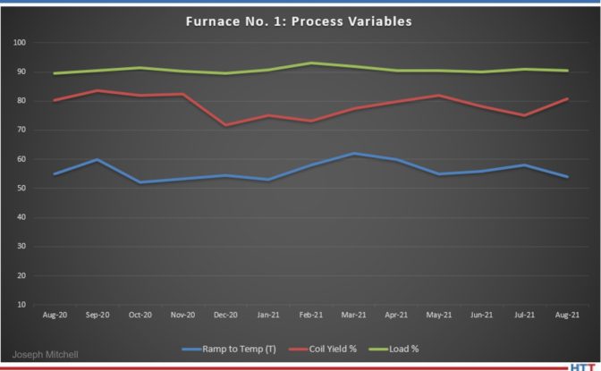
During initial installation stages, be sure to capture key process variables and the need for strategic placement of data gathering sensors based upon best opportunities for process impact like:
- furnace atmosphere / time / temperature
- material cleanliness / required microstructure / coil tension
- strip thickness / strip width / process routing / pre & post processing
Data input from locations other than annealing furnace are of equal concern:
- pickle tank temperature / acid concentration
- rinse tank temperature / cleanliness / cycle time
- surface roughness / temper rolls / anti-sticking oil
As noted earlier, I understand use of equipment that is in disrepair or outdated is a reality for some heat treaters; fortunately, use of SCADA system would provide necessary data to justify purchasing new equipment and/or upgrading old equipment. A data driven proposal presented in unbiased digital format is an advantage for showing upper-management current state-of-affairs and possible return on investment (ROI) if funding is provided and investments are made.
Diagnostic Analytics (Analyze)
At this point, we have a SCADA (or similar) system in place, either for a given furnace/machine, work-cell, or eventually for an entire manufacturing/processing system. In our case, the process parameters associated with sticking, and therefore the ones which need to be monitored, include temperature, time, pressure, surface condition, and reactivity.4 The stage for descriptive analytics is set; data is collected/summarized, but no direct decisions/predictions develop from this digital data stream. We learn "what happened” and proceed with the question, "why" did "X" happen? Thereby, we enter the world of diagnostic analytics in the quest for root causes, seeking to understand unusual events: why did no sticking occur when we processed alloy "A" last week, but this week alloy "A" exhibits sticking?
Following our statistical study used in descriptive and diagnostic analysis that was performed using data analysis software, we continue applying statistical methods for our investigation. The objective is discovery and confirmation of relationships and/or trends, which may relate to, or show causes for, sticking (coil wraps adhering together).
Predictive Analytics (Improve)
Rarely in a heat treating/material processing dilemma is the root cause readily disclosed; my experience in heat treating is that "bad" phenomenon often occur and disappear with impunity, leaving root cause analysis a moot point. We breathe a sigh of relief and enjoy the quiet before the next storm.
In the past, this unfortunate scenario likely resulted from one of two things: first, the inability to measure multiple variables simultaneously; and second, if a system is in place identifying and monitoring key variables, then management's inability of correlating (note: correlation may not ≠ causation) effects of multiple process variables. This inability leads to dependency and/or relationships preventing meaningful and/or accurate interpretation of data. At best, this does no more harm than allow the continued ill-effects of current problem, but at worst, it leads to incorrect conclusions, possible worsening of the problem at hand, and new problems.
Here is where management of forward-thinking companies -- focused on developing optimal manufacturing efficiencies, equipment effectiveness, increased profit, and competitive advantage --differentiate themselves by advocating application of digital technologies. In this case, it means moving toward artificial intelligence (AI); smart machines/machine learning.
Many options related to machine learning software and machine connectiveness are available (e.g., Siemens, GE Digital, Samsara, etc.). Your SCADA system provider is a great place for beginning investigation into predictive/prescriptive software solutions using machine learning tools.
Another example of a systems approach for digital transformation is Smart Prod ACTIVE. Profiled in Foundry Trade Journal last winter, this information and communication technology (ICT) platform, designed for optimizing foundry production, illustrates the growing possibilities for increased competitive advantage and profit growth based upon implementation of digital technologies, such as EnginSoft - smart ProdACTIVE.5
Prescriptive Analytics (Control)
Heat treating consists of many interrelated processes and/or systems. Prescriptive analytics, by way of simulation software/modeling tools, leads to applicable solutions; as Luigi Vanfretti, an associate professor of electrical, computer, and systems engineering at Rensselaer Polytechnic Institute, states, "You need to have a way to understand the interaction of the systems, and, in an integrated way, you need to optimize them together."6
Digital data collection and advanced analytics open the door for data-driven decisions and improved understanding of a process. When we are able to investigate cause-effect relationship(s) and our modeling tools suggest appropriate/optimal adjustment for non-normal process variation, we can achieve standardization of a given heat treating process, possibly even aimed at specific equipment in a manufacturing system.
In other words, the optimization factors of bell furnace "A" may not be optimal for bell furnace "B." The parameters for various aspects of the manufacturing system may need adjustment based on equipment performance/condition or other factors (e.g., coil mass, time at soak temperature, surface roughness (rolls), incoming strip cleanliness, etc.).
In this manner, continuous improvement throughout the manufacturing system becomes a part of our day-to-day business.
Digital Integration/Transformation
We examined a 21st century approach for resolving a 20th century problem: coil wraps sticking together post-anneal. This material processing phenomenon typically encountered when batch annealing ferrous or nonferrous materials may result from many interrelated process variables; that is, one or more sources of non-normal variation within a thermal processing system and/or manufacturing process.
The heat treating system, as well as the manufacturing system which is comprised of numerous material processes both upstream and downstream, requires continuous monitoring. As supported by CQI-9 (4th ed.), digital instrumentation is deemed necessary (for automotive suppliers) for surveillance and documentation of thermal processing parameters. Acquisition of digital data (e.g., SCADA) facilitates advanced analytics for predicting process outcomes and thereby prescribing optimal solutions which lead to process improvements.
Thus, application of digital monitoring/data collection, advanced analytics, and integration of Industry 4.0 technologies will enhance understanding, provide heretofore unknown process correlations/relationships, and thereby lead to problem mitigation.
As we close this article, some may ask, is digital transformation essential in our heat treating industry? Is IIOT and the all-encompassing Industry 4.0 a necessity for industrial heat treaters and others involved in material processing?
Perhaps a well-worn quote from W. Edwards Deming provides our answer: "It is not necessary to change. Survival is not mandatory."
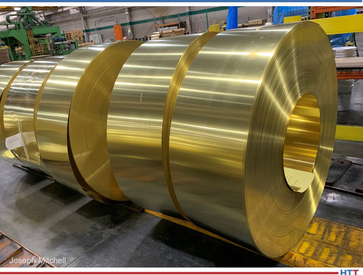
About the Author: Joseph Mitchell is director of Operations & Technology for The Miller Company, a service slitting center which supplies bronze and specialty copper alloy precision metal strip. With a BS in Industrial Management and MBA from Lawrence Technological University, his interests include metallurgy and practical application of Industry 4.0 concepts/digital technologies for developing business strategy that provide optimal use of assets, energy, and process controls within the metals and automotive industry.
References
1 J. Ryska, Industry 4.0 Meets the Stamping Line - Ford Motor Company's stamping division looks to leap into Industry 4.0 the same way Henry Ford led the transformation from Industry 1.0 to 2.0, Advanced Materials and Processes, Feb/Mar 2020, Vol 178, NO 2, p 25-28.
2 T. Daniels, "The Prevention of Sticking in Bright Annealing Sheet Steel,” Thesis; submitted for degree requirements, MS Chemical Engineering, Georgia School of Technology.
3 J.J. Bertrandie, L. Bordignon, P.D. Putz, G. Volger, Hot and Cold Rolling Processes, Sticking and Scratching Problems after Batch Annealing, including Coil Compression Stress Effects. Directorate-General Research, European Commission, Technical Steel Research, EUR 22059 EN, 2006, Sticking and scratching problems after batch annealing, including coil compression stress effects - Publications Office of the EU (europa.eu).
4 J.J. Bertrandie, L. Bordignon, P.D. Putz, G. Volger., p 21.
5 Foundry Trade Journal, Die Casting World, Vol. 194, No. 3771, Jan/Feb 2020, p 22.
6 Luigi Vanfretti, Modeling Electric Aircraft, Rensselaer Research, RPI, 2019 Research Report; Modeling Electric Aircraft | Office for Research (rpi.edu)
Additional resources mentioned in this article
Heat Treating with Digital Solutions for the 21st Century Read More »