

Why Normalize, and Is a ‘Still Air’ Cool Really Important? Part 2

The Heat Treat Doctor® has returned to offer sage advice to Heat Treat Today readers and to answer your questions about heat treating, brazing, sintering, and other types of thermal treatments as well as questions on metallurgy, equipment, and process-related issues.

This informative piece was first released in Heat Treat Today’s March 2025 Aerospace Heat Treating print edition.


Last time (Air & Atmosphere Heat Treating, February 2025) we addressed the question of why normalizing is necessary. Here we look at the importance of a “still air” cool on the final result. Let’s learn more.

What Is a “Still Air” Cool?

Contact us with your Reader Feedback!

As we learned last month, the term “cooling in air” is associated with normalizing but poorly defined in the literature or in practice, either in terms of cooling rate or microstructural outcome. This lack of specificity has resulted not only in many different interpretations of what is needed, but in a great deal of variability in the final part microstructure.

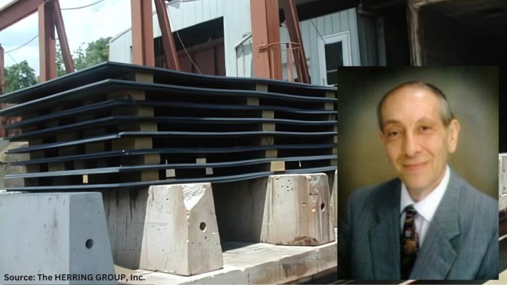
By way of example, this writer has on multiple occasions asked what changes are made to car bottom furnace cycles where cars are pulled outside of the plant for “air cooling” (Figure 1). Questions such as, is the furnace opened and the car pulled out in inclement weather? And, is this practice done on a particularly windy day, or in a rain or snowstorm or when the temperature is below zero? An all-too-common response is, “Only if it isn’t raining ‘too hard’ or snowing ‘too much’; then, we wait a while.” No wonder part microstructures are often found to vary from part to part and load to load!

Most heat treaters agree, however, that normalizing is optimized by a cooling in “still air.” This term also hasn’t been clearly defined, but it will be here based on both an extensive survey of the literature and the most common heat treat practices. In Vacuum Heat Treatment, Volume II, I define a still air cool as: “Cooling at a rate of 40°F (22°C) per minute … to 1100°F (593°C) and then at a rate of 15°F–25°F (8°C–14°C) per minute from 1100°F (593°C) to 300°F (150°C). Any cooling rate can be used below 300°F (150°C).”

Typical car bottom normalizing furnace opening to the outside environment

In addition, many consider nitrogen gas quenching in a vacuum furnace at 1–2 bar pressure to be equivalent to a still air cool. But again, so many factors are involved that only properly positioned workload thermocouples can confirm the above cooling rates are being achieved.

Also, many use the term “air cooling” to differentiate the process from “air quenching,” “controlled cooling,” and “fan cooling.”

Recall from the previous installment of this column that any ambiguity with respect to cooling rate ought to be defined in engineering specifications and/or heat treat instructions so that the desired outcome of the process can be firmly established.

From the literature, several important observations will serve as cautionary reminders. In STEELS, George Krauss points out that: “Air cooling associated with normalizing produces a range of cooling rates depending on section size [and to some extent, load mass]. Heavier sections air cool at much lower cooling rates than do light sections because of the added time required for thermal conductivity to lower temperatures of central portions of the workpiece.”

George Totten’s work in Steel Heat Treatment indicates: “Cooling … usually occurs in air, and the actual cooling rate depends on the mass which is cooled.” He goes on to state:

After metalworking, forgings and rolled products are often given an annealing or normalizing heat treatment to reduce hardness so that the steel may be in the best condition for machining. These processes also reduce residual stress in the steel. Annealing and normalizing are terms used interchangeably, but they do have specific meaning. Both terms imply heating the steel above the transformation range. The difference lies in the cooling method. Annealing requires a slow [furnace] cooling rate, whereas normalized parts are cooled faster in still, room-temperature air. Annealing can be a lengthy process but produces relatively consistent results, where normalizing is much faster (and therefore favored from a cost point of view) but can lead to variable results depending on the position of the part in the batch and the variation of the section thickness in the part that is stress-relieved.

In “The Importance of Normalizing,” this writer offers the following caution: “It is important to remember that the mass of the part or the workload can have a significant influence on the cooling rate and thus on the resulting microstructure.”

Finally, Krauss again observes: “The British Steel Corporation atlas for cooling transformation (Ref. 13.7) establishes directly for many steels the effect of section size on microstructures produced by air cooling.” (Note: Interpretation of continuous cooling transformation (CCT) curves will be the subject of a future “Ask The Heat Treat Doctor” column.)

Since hardness is one of the most commonly used criteria to determine if a heat treat process has been successful, it should also be noted that one can usually predict the hardness of a properly normalized part by looking at the J40 value when Jominy data is available.

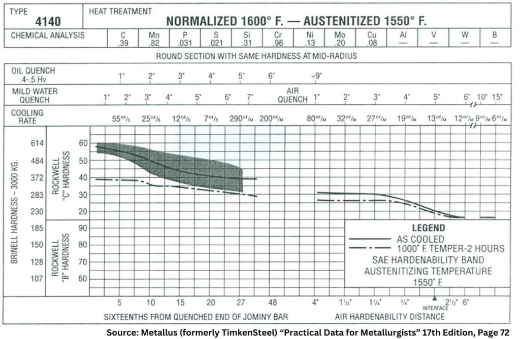
The Metallus (formerly TimkenSteel) “Practical Data for Metallurgists” provides an example of the type of data available to metallurgists and engineers to help define a required cooling rate for normalizing (Figure 2).

All literature references to normalizing agree (or infer) that the resultant microstructure produced plays a significant role in both the properties developed and their impact on subsequent operations.

Figure 2. Combined hardenability chart for normalized and austenitized SAE 4140 steel showing approximate still air cooling rates and resultant hardness (data based on a thermocouple located in the center of the bar diameter indicated)

Final Thoughts — The State of the Industry

It is all too common within the industry for some companies who wish to have normalizing performed on their products to specify only a hardness range on the engineering drawing or purchase order callout that is given to the heat treater.

Industry normalizing practice here in North America varies considerably from company to company. Normalizing instructions are sometimes, but not often enough, provided on either purchase orders, engineering drawings, or in specifications (industry standards or company-specific documents). These instructions range from, in the case of certain weldments, absolutely nothing (i.e., no hardness, microstructure, or mechanical properties) to referencing industry specifications (e.g., AMS2759/1) or specifying complete metallurgical and mechanical testing including hardness and microstructure.

Most commercial heat treaters often perform normalizing to client or industry specifications provided to them. Others prefer so-called “flow down” instructions in which the process recipe is provided to them. It is a common (and mistaken) belief that this removes the obligation of achieving a given set of mechanical or metallurgical properties even if they are called out by specification, drawing, or purchase order.

Also, the final mechanical properties that result from normalizing are seldom verified by the heat treater. Rather, a hardness value (or range) is reported, but hardness is not a fundamental material property, rather a composite value, one which is influenced by, for example, the yield strength, work hardening, true tensile strength, and modulus of elasticity of the material.

References

ASM International. “ASM Handbook, vol. 4, Heat Treating,” 1991.

ASM International. “ASM Handbook Volume 4A, Steel Heat Treating, Fundamentals and Processes,” 2013.

Chandler, Harry, ed. Heat Treater’s Guide: Practices and Procedures for Irons and Steels. 2nd ed, ASM International, 1995.

Grossman, M. A., and E. C. Bain. Principles of Heat Treatment, 5th ed, ASM International, 1935.

Herring, Daniel H. Atmosphere Heat Treatment, vol. I, BNP Media, 2014.

Herring, Daniel H. Atmosphere Heat Treatment, vol. II, BNP Media, 2015.

Herring, Daniel H. Vacuum Heat Treatment, vol. I, BNP Media, 2012.

Herring, Daniel H. Vacuum Heat Treatment, vol. II, BNP Media, 2016.

Herring, Daniel H. “The Importance of Normalizing,” Industrial Heating April 2008.

Krauss, George. STEELS: Heat Treatment and Processing Principles, ASM International, 1990. 463.

Krauss, George. STEELS: Processing, Structures, and Performance, ASM International, 2005.

Practical Data for Metallurgists, 17th ed. TimkenSteel, 2011

Totten, George E., ed. Steel Heat Treatment Handbook, vol. 2, 2nd ed., CRC Press, 2007.

About the Author

Dan Herring
“The Heat Treat Doctor”
The HERRING GROUP, Inc.

Dan Herring has been in the industry for over 50 years and has gained vast experience in fields that include materials science, engineering, metallurgy, new product research, and many other areas. He is the author of six books and over 700 technical articles.

For more information: Contact Dan at dherring@heat-treat-doctor.com.

For more information about Dan’s books: see his page at the Heat Treat Store.


Find Heat Treating Products And Services When You Search On Heat Treat Buyers Guide.Com


Why Normalize, and Is a ‘Still Air’ Cool Really Important? Part 2 Read More »

Aviation Research Improved with Vacuum Furnace

A manufacturer of aviation engine parts is enhancing its research capabilities with the acquisition of an adapted vacuum furnace to investigate the improvement of aviation components. The company has plans to build a new research center where the customized furnace will be used for laboratory materials testing.

Maciej Korecki
Vice President of Vacuum Business Segment
SECO/WARWICK

The manufacturer currently operates a SECO/WARWICK vacuum furnace used in the production of aircraft engine parts. The newly purchased Vector® furnace is equipped with isothermal quenching, which allows the cooling process to operate with better control of the load temperature and blower control using a frequency inverter. In addition, the SECO/PREDICTIVE system, a furnace monitoring and diagnostics option, allows users to detect the risk of failure before it occurs and thus minimizes unplanned downtime.

“Compact, specially adapted Vector furnaces are suitable for both scientific institutes and production plants that are looking for new material solutions and want to improve their components,” said Maciej Korecki, vice-president of the Vacuum Furnace Segment at SECO/WARWICK. “This furnace will not be used in series production, but in development processes, contributing to the creation of innovative solutions for the aerospace industry.”

SECO/WARWICK rebuilt the heating chamber so that the dimensions of the working space allow for effective development processes and installed a temperature uniformity system for temperatures reaching above 2372oF (1300oC). The purpose of personalization is to enable the system to produce an effective heat treatment of dedicated parts provided for the investment project, specifically R&D research on aircraft engine parts.

The Vector furnace designed for this client is characterized by the use of two gases: argon for partial pressure (ensuring the process purity, required by restrictive aviation standards) and nitrogen for hardening. It also has a dew point sensor for each gas. This is a system which solves one of the critical aspects of heat treatment, which is to prevent water vapor condensation, causing the processed load surface oxidation.

Press release is available in its original form here.


Aviation Research Improved with Vacuum Furnace Read More »
Quench Oil Management: AMS2759 & CQI-9

Given safety and performance concerns in the aerospace sector, it may be beneficial to consider quench testing that uses CQI-9 as well as AMS2759 since the automotive standard focuses on safety. Read on to understand the different approaches between these two standards in this Technical Tuesday installment, written by Michelle Bennett, quality assurance senior specialist, and Greg Steiger, senior account manager, both at Idemitsu Lubricants America.

This informative piece was first released in Heat Treat Today’s March 2025 Aerospace Heat Treating print edition.


In today’s world, there are many different quality systems available to heat treaters. Many of these, such as ISO, are quality management systems. These quality management systems are an important piece of running a successful business. However, to successfully run a heat treat business and compete in either the North American automotive market or the aerospace market, a heat treater must conform to either CQI-9 or AMS2759, or, in cases where a company processes both automotive and aerospace parts, both. This article will explain the requirements for both CQI-9 and AMS2759. It will also explain the differences between the two quality standards and any additional testing that could benefit a heat treater or how they operate their quench tank.

AIAG’s CQI-9

The Automotive Industry Action Group (AIAG) is a non-profit group of over 800 automotive OEMS, parts manufacturers, and service providers who oversee the requirements for CQI-9. The 4th edition is the most current edition of CQI-9. As an internal audit process, CQI-9 covers most of the heat treating process. Section 3.14 specifies the quench oil and water-soluble polymer requirements. An oil quenchant requires that the in-use oils be tested every six months and the testing must include water content, percent suspended solids, total acid number, viscosity, flash point, and cooling curve. The specification range and warning limits are based on the vendor’s requirements and recommendations. For water-based polymers, there are two tests required: concentration and quenchability. The standard does not specify a test for quenchability, however, it does make a few suggestions such as a cooling curve, viscosity, and titration.

For water-based polymers, there are two tests required: concentration and quenchability. The standard does not specify a test for quenchability, however, it does make a few suggestions such as a cooling curve, viscosity, and titration.

All the required testing of the quenchant is designed to achieve consistent metallurgy for safety reasons. Viscosity is monitored to look for oxidation or heat decomposition of the oil. Degradation can be in the form of oxidation, thermal breakdown, or the presence of various contaminants. Increased oil viscosity typically results in decreased heat transfer rates. A decrease in viscosity may indicate contamination. Some suspended solids are to be expected during the quenching process, but the majority of them should be filtered or centrifuged from the process. If the quantity of these contaminants becomes too high, then it can both affect the brightness of the parts, and the parts can get soft spots as the contaminants may not cool the parts at the same rate.

Water and flash point are both monitored for safety. If the flash point drops below the accepted range or the water content is above the acceptable range, these can cause fires during the operation. Water can also show issues with the equipment or the procedure such as leaking of anything that is water cooled, such as the outer door on a furnace. Acid value is monitored to degradation of the oil. As the oil breaks down and oxidizes, the acid value will increase. This can cause the maximum cooling rate to increase and can cause cracking or distortion on the parts. Carbon residue can be measured for two reasons. If the result is below the specification, it can show that the quench speed improver is being broken down or dragged out of the system. If the result is higher than the specification, it can show the formation of sludge, which will impact the brightness of the parts.

For water-based quenchants, the most common test items include pH, refractive index or brix, viscosity, and concentration calculation. Sometimes additional test items can be added, such as biological testing, to help determine and correct current issues.

Table 1. CQI-9 vs. AMS2759 quenchant requirements

SAE’s AMS2759

Just as AIAG is a non-profit business group responsible for CQI-9, SAE International is a non-profit organization responsible for AMS2759. The most recent revision of AMS2759 is Revision G. AMEC (the Aerospace Materials Engineering Committee) is responsible for maintaining this standard. Unlike CQI-9, AMS2759 requires a certificate of conformance for all shipments. Section 3.10.3 begins the requirements for quenchant testing and quenchant deliveries. Viscosity, flash point, and temperature at the maximum cooling rate must be reported on the certificate of compliance when dealing with mineral oil quenchants. For a polymer, the requirements are that the pH of the neat polymer and the neat viscosity of the polymer must both be reported on the certificate. Also required on the polymer certificate are the viscosity, pH, and the temperature at the maximum cooling rate for polymers at 20% dilution by weight.

Similarly to CQI-9, AMS requires that the in-use quenchants be tested biannually. This standard, however, only requires the cooling rate and temperature at max cooling rate be tested, as well as any additional tests the supplier recommends. The AMS2759 specification does not have set limitations on the cooling rate and temperature. Instead, the specification sets the allowed upper and lower deviations from the supplier’s standard for the maximum cooling rate and the temperature at the maximum cooling rate for both oils and water-soluble polymers. The supplier should have calculated the average max cooling rate and average temperature at max cooling rate using many different blend lots and multiple test runs. This average will not vary or change based on current production values or the values for the batch that the client is currently using (Table 1).

Although both standards require having the quenchant tested bi-yearly, most quenchant suppliers encourage their clients to submit their furnace samples for testing quarterly. This ensures that the medium is being monitored frequently, and if a sample is missed or late when sampling quarterly, then the client is still within compliance for the six month testing requirements.

However, because many of the test parameters in CQI-9 are run for safety reasons along with performance reasons, it is highly advised that aerospace heat treaters should run the full suite of CQI-9 testing along with the AMS2759 testing.

Taking a Quench Sample

There are many different quench methods and both standards allow for any of the following variations: ASTM D6200, ISO 9950, JIS K2242, ASTM D6482, or ASTM D6549. The type of testing that is going to be conducted will determine the size of sample that will be needed. For just this quench testing, the volume of sample needed ranges from 250 milliliters to 2 liters.

As always, when taking samples, it is important to be sure to get a good representative sample of the current quenchant being used in the process. The agitation needs to be running and collected in a clean and dry container. The sampling site should be the most convenient location to safely obtain a sample. It should also be the same location for every sample. The lid also needs to be put on before the oil cools too much because the container will draw in moisture and condensation as the oil cools if it is open to the atmosphere.

Conclusion

When examining the standards, there is one basic commonality: the need to run a complete cooling curve every six months. There is also a large difference in that AMS2759 does not require the full suite of testing that CQI-9 does. However, because many of the test parameters in CQI-9 are run for safety reasons along with performance reasons, it is highly advised that aerospace heat treaters should run the full suite of CQI-9 testing along with the AMS2759 testing. For automotive heat treaters, the maximum cooling rate and the temperature at maximum cooling rate is something that can be reported in the normal D6200 cooling curve test.

For manufacturers heat treating parts for aerospace, automotive, or both markets, we recommend quarterly quench samples at a minimum. The primary reason for more frequent testing is safety. Also, with the current labor shortage, heat treaters are busier than ever. If quench samples are routinely taken on a quarterly basis and are somehow missed and forgotten, there is still time to take another sample and remain in CQI-9 and AMS2759 compliance.

Remaining in compliance of these two important standards requires a lot of hard work from both the heat treater and the quenchant provider. Unless the quenchant supplier is working together in a true partnership, it will be very difficult to remain in compliance with the requirements for CQI-9 and AMS2759. But with routine monitoring, heat treaters can help to ensure quenchant and equipment have a longer life and achieve ever-tightening requirements from clients.

About The Authors:

Michelle Bennett
Quality Assurance Senior Specialist
Idemitsu Lubricants America

Michelle Bennett is the quality assurance senior specialist at Idemitsu Lubricants America, supervising the company’s I-LAS used oil analysis program. Over the past 12 years, she has worked in the quality control lab and the research and development department. Her bachelor’s degree is in Chemistry from Indiana University. Michelle is a recipient of Heat Treat Today’s 40 Under 40 Class of 2023 award.

Greg Steiger
Senior Account Manager
Idemitsu Lubricants America

Greg Steiger is the senior account manager at Idemitsu Lubricants America. Previous to this position, Steiger served in a variety of technical service, research and development, and sales and marketing roles for Chemtool Incorporated, Witco Chemical Company, Inc., D.A. Stuart Company, and Safety-Kleen, Inc. He obtained a BS in Chemistry from the University of Illinois at Chicago and recently earned a master’s degree in Materials Engineering at Auburn University. He is also a member of ASM International.

For more information: Contact Michelle Bennett at mbennett.8224@idemitsu.com or Greg Steiger at gsteiger.9910@idemitsu.com.


Quench Oil Management: AMS2759 & CQI-9 Read More »

Heat Treat Economic Indicators: March 2025 Results

The four heat treat industry-specific economic indicators have been gathered by Heat Treat Today each month since June 2023. As the northern hemisphere looks to warmer weather, a positive outlook is reflected in three of the four economic indicators compiled in the first week of March.

Heat treat industry suppliers anticipate the economy in March to experience growth in number of inquiries, value of bookings, and size of backlog, however there is a net decrease compared to February. This is particularly shown in the economic indicators where suppliers to the North American heat treat industry expect no change over previous months in health of the manufacturing economy.

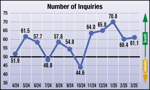
The results from this month’s survey (March) are as follows; numbers above 50 indicate growth, numbers below 50 indicate contraction, and the number 50 indicates no change:

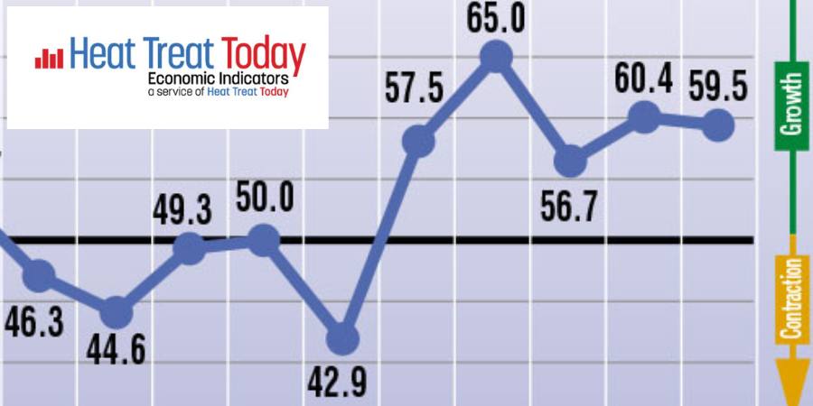
  • Anticipated change in Number of Inquiries from February to March: 61.1
  • Anticipated change in Value of Bookings from February to March: 58.8
  • Anticipated change in Size of Backlog from February to March: 59.5
  • Anticipated change in Health of the Manufacturing Economy from February to March: 50.0

Data for March 2025

The four index numbers are reported monthly by Heat Treat Today and made available on the website. 

Heat Treat Today’s Economic Indicators measure and report on four heat treat industry indices. Each month, approximately 800 individuals who classify themselves as suppliers to the North American heat treat industry receive the survey. Above are the results. Data started being collected in June 2023. If you would like to participate in the monthly survey, please click here to subscribe.


Heat Treat Economic Indicators: March 2025 Results Read More »
This Week in Heat Treat Social Media

Welcome to Heat Treat Today’s This Week in Heat Treat Social Media. We’re looking at addendum learning, indepth instruction from industry leaders, and how-tos that will tickle your ears. But first in the posts, podcasts, and videos we have rounded up for you, check out what NASA is doing with shape-shifting tires.

As you know, there is so much content available on the web that it’s next to impossible to sift through all of the articles and posts that flood our inboxes and notifications on a daily basis. So, Heat Treat Today is here to bring you the latest in compelling, inspiring, and entertaining heat treat news from the different social media venues that you’ve just got to see and read! If you have content that everyone has to see, please send the link to editor@heattreattoday.com.


1. Entering the Realm of Shape-Shifting

This space is usually reserved for something rich and technical, so we’re looking at the science of shape-shifting!

Check out this recent post on ThomasNet about NASA’s foray into the world of physical transformations.

2. It’s a Beautiful Day in the Heat Treat Neighborhood

Don’t Skip the Side Trips!

Trades Schools Now Trending

Helping Kids Take Flight

3. A broad Education in Heat Treating Coming Your Way

Sometimes, it’s the small things on social media that grab your attention or give you the “ah ha!” moment. And sometimes things affecting the industry in other places cause us to go “hmm.” Do any of these short posts make you say “eureka”?

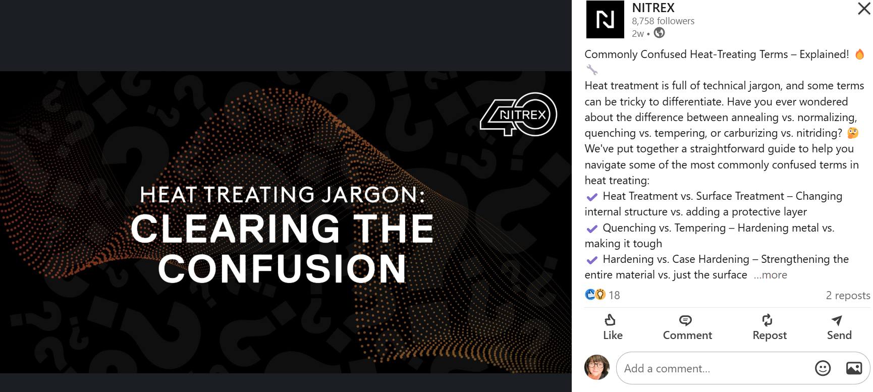
How many Terms Do You Already Know?

All About Quenching

Monitoring Leaks and Dew Point Gases

Having a Blast with Furnaces

4. Open Your Eyes & Ears: The Podcast Corner

You can’t read everything, we get it. Heat Treat Today is here to recommend two informative podcasts and one video to enjoy on your daily commute or during your evening roundup.

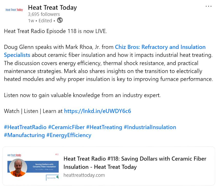
Tune in to Listen to Heat Treat Radio #118: Saving Dollars with Ceramic Fiber Insulation

Heat Treating Machined Parts To enhance strength, hardness, durability, and flexibility

Carlos Torres Interviews Steve Kowalski on the Heat Treat Podcast

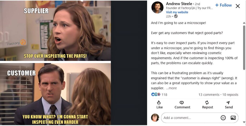
5. Inspections Are Good … Overinspections Can Be Too Good

Have a great weekend!


This Week in Heat Treat Social Media Read More »

El PF y el DPF: ¿importan?

As heat treating facilities strive for energy efficiency and reliability, investing in power improvements can move a company toward sustainable operations. In this Controls Corner installment, Brian K. Turner of RoMan Manufacturing, Inc. compares real power factor and displacement power factor in the efficiency and electrical performance of vacuum furnaces.

This informative piece was first released in Heat Treat Today’s February 2025 Air/Atmosphere Furnace Systems print edition.

To read the article in English, click here.


En el contexto de los hornos de vacío, el factor de potencia real y el factor de potencia de desplazamiento son conceptos claves en relación a la eficiencia y el comportamiento tanto de la fuente de energía eléctrica como de la carga del horno. A continuación, una comparación entre los dos factores.

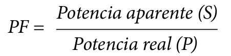
1. El factor de potencia real (PF, por sus siglas en inglés)

Definición: El factor de potencia real es la relación entre la potencia real (potencia activa, P, medida en vatios) y la potencia aparente (S, medida en voltamperios). Da cuenta tanto del desplazamiento de fase como de la distorsión armónica.

Relevancia para hornos de vacío:

  • Los hornos de vacío, en particular los que funcionan con calentamiento por inducción, con frecuencia generan cargas no lineales debido a la operación de la electrónica de potencia.
  • Las cargas no lineales conllevan armónicos que distorsionan la forma de onda de la corriente generando una disminución en el factor de potencia real.
  • Un bajo factor de potencia real es indicador de ineficiencia ya que el sistema se ve obligado a aumentar el consumo de potencia aparente para generar la potencia real que se requiere.

2. El factor de potencia de desplazamiento (DPF, por sus siglas en inglés)

Definición: El factor de potencia de desplazamiento es el coseno del ángulo (ϕ) entre dos componentes fundamentales: el voltaje y las formas de onda de la corriente.

Relevancia para hornos de vacío

  • En los hornos de vacío la esencia inductiva de los componentes (p.ej., los transformadores y las cargas inductivas) genera un factor de potencia de retardo que se ve reflejado en el DPF.
  • Un bajo factor de potencia de desplazamiento (es decir, con retardo importante) implica demandas significativas para el sistema en cuanto a potencia reactiva, lo que a su vez afecta el tamaño de los transformadores y del equipo de distribución de energía.

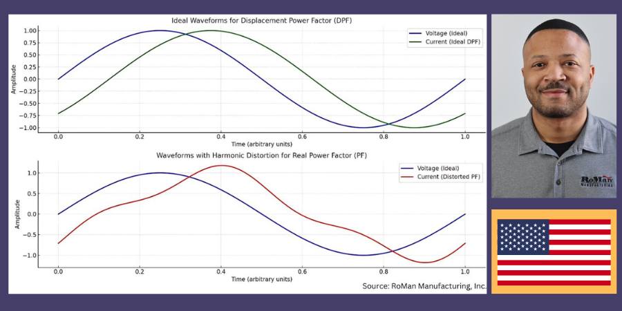
Tabla superior: DPF – Condiciones ideales

  • La forma de onda sinusoidal verde representa la corriente en un escenario con factor de desplazamiento de potencia ideal en el que interviene únicamente el desplazamiento de fase (ϕ) entre el voltaje (curva azul) y la corriente.
  • Las formas de onda se ven limpias y sinusoidales, indicando la ausencia de distorsión armónica.

Tabla inferior: PF — Con distorsión armónica

  • La forma de onda roja representa la corriente con la intervención de la distorsión armónica, situación típica de sistemas con cargas no lineales, caso de los hornos de vacío.
  • Esta distorsión genera una disminución en el factor de potencia real frente al factor de potencia de desplazamiento, aún cuando no se haya modificado la relación en la fase fundamental.
Formas de onda que permiten visualizar el DPF vs. el PF en relación a voltaje y corriente

Efecto sobre el tamaño de transformadores y transformadores de distribución

Aumento en la demanda de potencia aparente

  • Un factor de potencia real disminuido (debido a los armónicos) implica que el transformador deberá manejar una mayor potencia aparente (S) sin importar que la potencia real (P) no haya cambiado. Esto puede aumentar los costos de capital al requerir transformadores más grandes.

Estrés térmico

  • Los armónicos llevan a pérdidas adicionales (por las corrientes inducidas y la histéresis) generando el sobrecalentamiento de los transformadores y disminuyendo la eficiencia y duración de los mismos.

Regulación de voltaje

  • Los armónicos distorsionan la forma de onda del voltaje, lo que podría afectar los equipos sensibles y obligar al uso de transformadores capaces de regular de manera más precisa el voltaje.

Penalización por consumo energético

  • Los proveedores del servicio de energía muchas veces aplican sanciones por un bajo factor de potencia real, con lo que buscan incentivar a los usuarios a mejorar la calidad de la potencia mediante el uso de filtros armónicos o corrección del factor de potencia.

Conclusión

La revisión del factor de potencia en los hornos de vacío es de crítica importancia para lograr una mayor eficiencia y la reducción de los costos operativos. En su avance hacia la eficiencia y la fiabilidad energética, invertir en estas mejoras permitirá a las plantas de tratamiento térmico acercarse un paso más a la operatividad sostenible.

Traducido por: Shawna Blair

About the Author:

Brian Turner
Sales Applications Engineer
RoMan Manufacturing, Inc.

Brian K. Turner has been with RoMan Manufacturing, Inc., for more than 12 years. Most of that time has been spent managing the R&D Lab. In recent years, he has taken on the role as applications engineer, working with customers and their applications.

Para contactar a Brian: bturner@romanmfg.com.


El PF y el DPF: ¿importan? Read More »

MTI Member Profile: Contour Hardening

If you had to describe Contour Hardening, Inc., in one phrase, it would be: Engineers solving problems. When a client encounters a part failure, this heat treater believes their work has just begun. Founded in 1986 by two engineers (one a metallurgical engineer and one a gear engineer), the company has been solving complex problems with unique, custom designed solutions ever since.

The first problem Contour’s two founding engineers solved was how to handle gears that have such irregular shapes but still need a high degree of case depth and pattern accuracy. What they created is the unique and patented Micropulse™ Process. In the ‘80s, their strategy was to build this advanced, computer-controlled induction heating technology into custom-designed induction hardening machines for OEM manufacturers and tier 1 suppliers. This patented process is a slightly different hardening solution than other available options. Specifically, this process prioritizes keeping the part below the critical temperature zone. Heat times can be controlled to the millisecond, and the time at which the part is above critical temperature can be as low as 0.15 seconds. In addition to this tight temperature control is the ability to use dual frequencies, which provides the custom solution the founding engineers sought after: A heat pattern that precisely contours to the surface of the part.

Zion’s ZSCAN induction scanner outfitted with full-service controls

Equipment — or lack of customized equipment — is another problem to solve on Contour’s list. The company often functions as most commercial heat treaters do, receiving work to process in their on-site equipment. This equipment includes 12 case hardening machines and nitriding and ferritic nitrocarburizing machines. Custom designed equipment, however, also leaves the company’s Indiana or Mexico facilities and is delivered to clients as needed. This is because the company functions with the motto that pre-designed machines are not always best, and sometimes, you just have to build the machine around the part, not the part around the machine. This motto has led Contour to solve many a client’s failure with a unique, built-to-client-speculation machine, delivered on time.

What is Contour’s next set of problems to solve? In the upcoming years, the company is looking forward to providing solutions to bridge the gap between design constraints and manufacturing feasibility. Unmanned drones and electric vehicles are two of the key players in this area. On a broader scale, the company hopes to find a solution that fits the torque requirements of electric motors, as well as keeps the size of components small. Whatever the next problem may be, this group of engineers and heat treaters is prepared to tackle it.

For more information:

Contour Hardening, Inc.

8401 Northwest Boulevard
Indianapolis, IN 46278
United States

nmerrell@contourhardening.com
www.contourhardening.com

Main image: Transmission gear above Curie temperature, contouring the surface


MTI Member Profile: Contour Hardening Read More »

Why PF and DPF Matter

As heat treating facilities strive for energy efficiency and reliability, investing in power improvements can move a company toward sustainable operations. In this Controls Corner installment, Brian K. Turner of RoMan Manufacturing, Inc. compares real power factor and displacement power factor in the efficiency and electrical performance of vacuum furnaces.

This informative piece was first released in Heat Treat Today’s February 2025 Air/Atmosphere Furnace Systems print edition.

To read the article in Spanish, click here.


In the context of vacuum furnaces, real power factor and displacement power factor are key concepts related to the efficiency and electrical performance of the furnace’s power supply and load. Here’s a comparison:

1. Real Power Factor (PF)

Definition: Real power factor is the ratio of real power (active power, P, measured in watts) to apparent power (S, measured in volt-amperes). It considers both the phase displacement and harmonic distortion.

Relevance to Vacuum Furnaces:

  • Vacuum furnaces, especially those using induction heating, often generate nonlinear loads due to the operation of power electronics.
  • Nonlinear loads introduce harmonics, which distort the current waveform, reducing the real power factor.
  • A low real power factor indicates inefficiency, as the system draws more apparent power for a given amount of real power.

2. Displacement Power Factor (DPF)

Definition: Displacement power factor is the cosine of the angle (ϕ) between the fundamental components of voltage and current waveforms. It ignores harmonic distortion and considers only the phase displacement caused by inductive or capacitive loads.

Relevance to Vacuum Furnaces

  • In vacuum furnaces, the inductive nature of components (e.g., transformers and inductive loads) causes a lagging power factor, which is reflected in the DPF.
  • A poor displacement power factor (e.g., heavily lagging) means the system has significant reactive power demands, affecting the sizing of transformers and power distribution equipment.

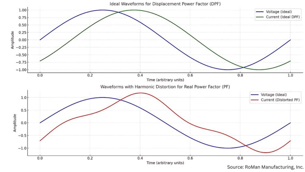
The above waveforms illustrate the difference between displacement power factor (DPF) and real power factor (PF) as they relate to current and voltage:

Top Chart: DPF — Ideal Conditions

  • The green sinusoidal waveform represents the current in an ideal displacement power factor scenario, where only phase displacement (ϕ) exists between the voltage (blue curve) and current.
  • The waveforms are clean and sinusoidal, indicating no harmonic distortion.

Bottom Chart: PF — With Harmonic Distortion

  • The red waveform represents the current with added harmonic distortion, typical in systems with nonlinear loads, like vacuum furnaces.
  • This distortion causes the real power factor to drop compared to the displacement power factor, even if the fundamental phase relationship is the same.
Waveforms that illustrate DPF vs. PF as it relates to voltage and current

Effects on Transformer and Utility Transformer Sizing

Increased Apparent Power Demand

  • A lower real power factor (due to harmonics) means the transformer must handle higher apparent power (S), even if the real power (P) is unchanged.
  • This can necessitate larger transformers, increasing capital costs.

Thermal Stress

  • Harmonics lead to additional losses (eddy currents and hysteresis), causing transformers to overheat and reducing their efficiency and lifespan.

Voltage Regulation Issues

  • Harmonics distort the voltage waveform, which can affect sensitive equipment and require transformers with tighter voltage regulation capabilities.

Utility Penalties

  • Utilities often impose penalties for low real power factor, incentivizing users to improve power quality through harmonic filters or power factor correction.

Conclusion

Addressing power factor in vacuum furnaces is crucial for improving efficiency and reducing operational costs. As heat treating facilities strive for energy efficiency and reliability, investing in these improvements is a step toward sustainable operations.

About the Author:

Brian Turner
Sales Applications Engineer
RoMan Manufacturing, Inc.

Brian K. Turner has been with RoMan Manufacturing, Inc., for more than 12 years. Most of that time has been spent managing the R&D Lab. In recent years, he has taken on the role as applications engineer, working with customers and their applications.

For more information: Contact Brian at bturner@romanmfg.com.


Why PF and DPF Matter Read More »