MANUFACTURING HEAT TREAT

Marc Glasser on The Tools and Trade Secrets of Heat Resistant Alloy Welding

Heat resistant alloys used for heat treating fixtures, muffles, retorts, radiant tubes, and other parts are typically stainless steel or nickel based austenitic alloys. Welding of these alloys requires practices that are often exactly the opposite of the practices required for carbon and alloys steels since austenitic stainless steels do not undergo phase transformations. Metallurgists are often asked many questions on the proper welding methods. Carbon and alloy steel welding requires practices and procedures that will minimize or prevent the chances of cracking due to potential martensite formation during weld solidification. Austenitic stainless steels do not undergo any phase transformation. They require rapid cooling to prevent solidification cracks due to hot cracking. Thus different procedures are required.

In this Heat Treat Today Technical Tuesday feature, Marc Glasser, Director of Metallurgical Services for Rolled Alloys, provides some basic information on the metallurgy as well as good welding practices to follow.

Reprinted with permission from Heat Treat 2019: Proceedings of the 30th Heat Treating Society Conference and Exposition, October 15-17, 2019, Detroit, Michigan, USA. ASM International, 2019.


CHEMISTRY CONSIDERATIONS
Most heat resistant alloys used in the heat treating industry for components are austenitic. They can be austenitic stainless steels, or austenitic nickel alloys. The key word is austenitic. One of the virtues of austenitic materials is that they are not subject of phase changes from cooling to heating or heating to cooling. This is markedly different from alloy and carbon steels, which undergo a phase transformation from austenite to ferrite and cementite. The cooling must be slow enough to prevent martensite formation, so preheating and postheating are performed to either prevent this phase transformation or to temper any formed martensite.

Austenitic alloys do not undergo phase transformations to martensite, and as a result slow cooling the material is the worst operation that an austenitic alloy can be subject to. In austenitic alloys, the main concern is the tendency for welds to hot tear upon solidification[1]. In stainless steels with up to approximately 15% nickel, the solution is simple. The composition is adjusted to form small amounts of ferrite during solidification[2]. Prediction of the ferrite number FN, which represents an estimate of the amount of ferrite in the weld after solidification, is predicted by using Schaeffler diagrams. The ferrite nullifies the effect of certain trace elements that cause hot cracking [1]. One of these trace elements, phosphorous cannot be refined out of the material. Since these materials are all melted from scrap metal, the amount of phosphorous found in the heat will mirror the amount in the scrap. Sulfur, silicion, and boron also contribute to hot shortness, but these elements can be refined to very low levels in the steelmaking process.

For higher nickel bearing grades, with more than 20% nickel, the chemistry precludes the possibility of ferrite formation. Therefore, other means must be employed to prevent hot tearing during solidification. In this case, the residual trace elements, particularly P must be kept low, as they lead to hot shortness [2, 3]. Certain alloy additions including manganese (Mn), niobium (Nb), molybdenum (Mo), and carbon (C) all reduce the propensity of austenitic nickel alloys and high nickel stainless steels to crack [4]. 310 stainless steel stans in a unique position having neither ferrite formers nor weldability-enhancing alloy additions. In this alloy, control of chemistry and residuals is of utmost importance.

The other key to successful welding of nickel alloys is to minimize the time spent in the high temperature range where they are susceptible to hot tearing [4].

GOOD WELDING PRACTICES
Good welding practices for nickel alloys are centered on the need to remove heat as quickly as possible in order to minimize the time spent in the hot tearing range. The first consideration is to keep the heat input as low as possible to still get a full penetration weld. The actual input in kJ is dependent on the alloy being welded.

Heat input (HI) is defined as: HI (KJ/in) = Voltage x Amperage x 6/(Speed (inch/min) x 100)

Welds should NOT be preheated and interpass temperatures should be 200°F maximum. The cooler the interpass temperature is, the less likely hot tearing is [5]. A reliable, easy test for a welder is the spit test. Spit on the weld, and if it boils it is still to hot, and further waiting is in order.

One of the most important considerations in welding nickel alloys is to weld in a straight line along the length of the weld and do not weave. Welders tend to weave from side to side especially when welding nickel alloys which are more viscous that carbon steels and this weaving makes the metal flow better. While this technique works well for carbon steel where a higher heat input and slower cooling are necessary, it is exactly the wrong procedure for nickel alloys. Weaving tends to flatten out a weld. This in turn reduces the crown height and strength.

Furthermore, weaving tends to increase the heat going into the weld and slow down the weld speed. The key is to get a nicely shaped, convex weld bead, as illustrated in Figure 1. A concave bead configuration tends to crack along the centerline [5].

Figure 1: Convex vs. Concave Weld

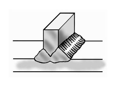
Full penetration welds are important. Beveling one or more of the pieces to be joined may be required to get a full penetration weld. Incomplete penetration leaves a void between the two workpieces. Such a channel can entrap surface treating gases leading to brittle pieces surrounding the weld. Furthermore, the gap can act as a propagation site for cracks which form from thermal cycling from heat treating. This is shown in Figure 2 below.

Figure 2: The effect of non fully penetrated welds

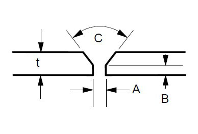
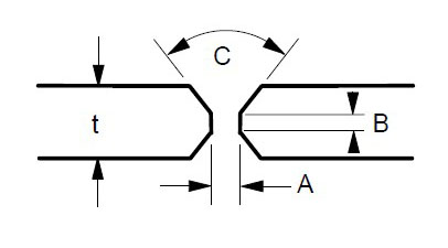
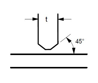
Some suggested joint designs include square butt joint, single V joint, double V joint, single U joint, double U joint, J groove joint, and T Joint. These are shown in Figures 3 to 9 below, along with design criteria. These suggestion grooves are from ASME code[6], but are good guidelines to follow even if code stamps are not required.

Figure 3: Square butt joint. Maximum t = 1/8 ” Gap A = 1/16″ Minimum, 3/32″ Maximum
Figure 4: Single V Joint. Maximum t = 1/2″ Gap A = 1/16″ Minimum, 1/8″ Maximum Land B = 1/16 to 3/32″ Angle C = 60 – 75 degrees
Figure 5: Double V Joint. Gap A = 1/16″ Minimum, 1/8″ Maximum Land B = 1/16 to 3/32″ t = 1/2″ or greater Angle C = 60-75 degrees
Figure 6: Single U Joint. Gap A = 1/16″ Minimum, 1/8″ Maximum Land B – 1/16 to 3/32″ Radius R – 3/8″ Minimum For single groove welds on heavy plate thicker than 3/4 inch. Reduces the amount of time and filler metal required to complete the weld.
Figure 7: Double U Joint. Gap A = 1/16 to 1/8″ Land B = 1/16 to 3/32″ Radius R = 3/8″ Minimum Minimum t = 3/4″
Figure 8: J Groove Joint. Gap A = 1/16 to 1/8″ Land B = 1/16 to 3/32″ Radius R – 3/8″ Minimum For single groove welds on plates thicker than 3/4 inch. Reduces the amount of time and filler metal required to complete the weld.
Figure 9: T Joint.
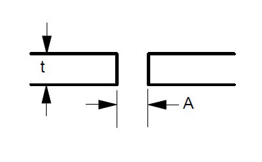
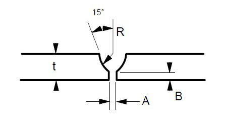
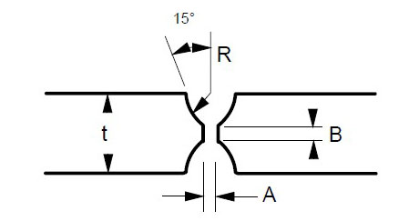
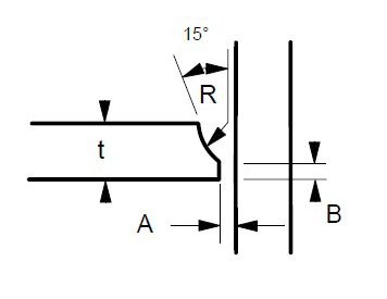
t = greater than 1/4″
For joints requiring maximum penetration. Full penetration welds give maximum strength and avoid potential crevices.

Regardless of which joint is selected, the purpose is to obtain a full penetration weld with no voids or channels, as shown in Figure 10 below.

Figure 10: Example of Full Penetration Weld

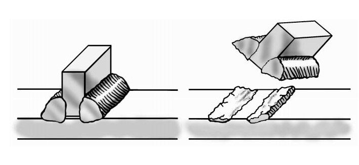
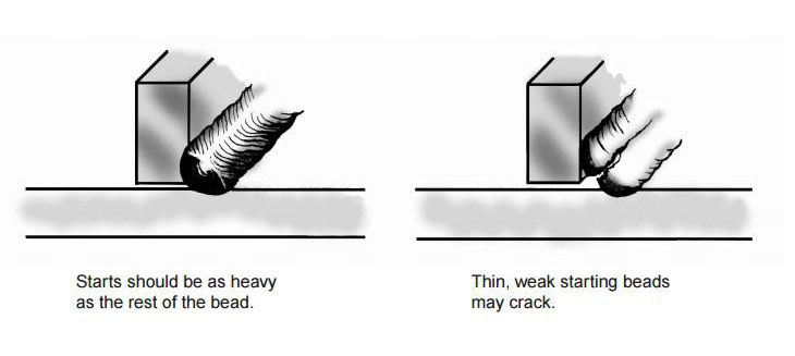
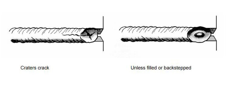
Both the starting and finishing ends of the weld beads can be crack initiation sites. The best practice for starting is to make the start of the weld bead as heavy as the rest of the weld bead [4]. A light or thin start up can cause cracking. This is shown in Figure 11. Furthermore, in nickel alloys, the end of the bead can sometimes yield a star shaped crack. This can be eliminated by backstepping the weld for ½ to 1 inch as shown in Figure 12 [3].

Figure 11: Start welds as heavy as the rest of weld beads
Figure 12: Backstep the weld ends to prevent cracking

Cleanliness is extremely important for welding stainless and nickel alloys. Some general rules include [5]:

  • Remove all shop dirt, oil, grease, cutting fluids, lubricants, etc. from welding surface and on the area 2 inches wide on each side of the weld joint with suitable cleaning agent.
  • Eliminate all sources of low melting metal contaminants from paints, markers, dies, back up bars, etc. Chromium plate copper back up bars can form a barrier between copper and the weld surface. Copper can cause HAZ cracking in nickel alloys. These low melting contaminants cause cracking and failures in nickel alloy and stainless steel welds. Avoid using lead or copper hammers in fabrication shops.
  • Grind clean the surfaces and the HAZ areas. Chromium scales melt at higher temperatures than the base metals and will not be reduced by filler metals.
  • When welding to nickel alloy or stainless to plain carbon steel, the plain carbon steel must be ground on both sides too.

SHIELDING GASES
Bare wire welding requires a shielding gas to protect the weld from oxidation, loss of some elements to slag or oxide formation, and contamination.

Most stainless steel and nickel alloys require 100% argon for shielding for the GTAW or TIG process.

GMAW or MIG welding has two distinct modes of metal transfer. Spray arc processing transfers metal between wire tip and workpiece as droplets. Short circuit processing transfers the metal in sheets or globules. The most common shielding gas for spray arc GMAW welding is 100% argon. 10-20% helium can be added along with small amounts of carbon dioxide (1% max) to improve bead contour and reduce arc wander [1]. Short circuit GMAW welding uses blends of inert gases usually either 75% argon – 25% helium or 90% helium – 7.5% argon – 2.5% carbon dioxide.

In order to prevent hot cracking with the GMAW process, 602CA® requires a unique blend of 90% argon – 5% helium – 5% nitrogen and a trace (0.05%) carbon dioxide. This blend was trademarked as Linde CRONIGON® Ni30. It is not readily available but there are other close alternate quad gas blends that are commercially available. For GTAW welding, argon with 2.5% nitrogen is used to prevent cracking in 602CA. The nitrogen is the key to preventing cracking in 602CA regardless of method.

RESTRAINT AND DISTORTION CONTROL
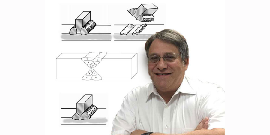
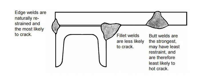
Weld metal shrinks as it freezes. To accommodate the dimensional changes associated with freezing, either the base metal or the weld must move to prevent cracking or tearing. In complex assemblies with multiple welds, each weld, when solidified functions as a stiffener, further restricting movement of subsequent welds. In such cases, the most difficult or crack susceptible weld in the assembly should be made first and the easiest and strongest welds should be made last [5]. An example is shown in Figure 13 below.

Figure 13: Welding with multiple welds. In this example, the edge weld on the left would be the first weld made. The fillet weld in the middle should be the second made, and the butt weld on the right would be the last one made

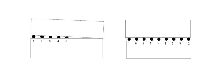
When multiple tack welds must be made, they should be sequenced along the length of the plate [5]. Tack welding from one end to the other that is made in order will result in plate edges closing up as shown in Figure 14.

Figure 14: Tack welding in order along plate edge (left) can close up and distort the joint. Sequencing the tack welds (right) can greatly reduce distortion

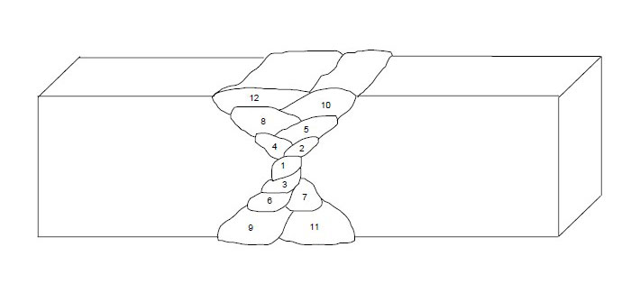
Finally, multipass welds should be sequenced around the center of gravity of the joint as shown in Figure 15 below.

Figure 15: Proper sequencing of multipass welds

REFERENCES
[1] Schaefer, Anton L, Constitution Diagram for Stainless Steel Weld Metal. Metal Progress. ASM, Metals Park, OH. P 680-683. November 1949.
[2] Ogawa T. & Tsunutomi, E. Hot Cracking Susceptibility of Austenitic Stainless Steel. Welding Journal, Welding Research Supplement. P 825-935. March, 1982
[3] Li, L & Messler, R. W. The Effects of Phosphorous and Sulfur on Susceptibility to Weld Hot Cracking in Austenitic Stainless Steels. Welding Journal. Dec. 1999, Vol 78, No. 12.
[4] Kelly J. Heat Resistant Alloys. Art Bookbindery. Winnepeg, Manitoba, Canada. 2013
[5] Kelly J. RA330, Heat Resistant Alloy Fabrication. Rolled Alloys. Temperance, MI. May, 1999
[6] ASME Boiler and Pressure Vessel Code. American Society of Mechanical Engineers. New York, NY. 2013.


Marc Glasser on The Tools and Trade Secrets of Heat Resistant Alloy Welding Read More »

Machine Tool Manufacturer Streamlines with In-House Heat Treat

A machine tool manufacturer has decided to create their own “captive” heat treat department.  The company has consequently invested in two different, yet complementary, vacuum heat treatment furnaces.

The CaseMaster Evolution® multi-chamber vacuum furnace (source: SECO/WARWICK)

As is often the case with companies thinking about how to gain better control of their production systems, one of the obvious bottlenecks for the customer was their offsite heat treatment arrangement. While quality from their existing suppliers was not an issue, it was clear that logistics could certainly be streamlined by eliminating the need to outsource parts to an external heat treater. The furnace manufacturer helped them weigh the pros and cons of moving their heat treatment processes into the plant. Ultimately, a decision was made to set up their own department, invest in new vacuum heat treat equipment, and train their production technicians to perform this critical function of the plant.

SECO/WARWICK received an order for a multi-chamber carburizing vacuum furnace with integral gas or oil quench, and a high pressure gas quench vacuum furnace capable of quench pressures up to 15-Bar.

The Vector® 15-Bar high pressure gas quench vacuum furnace (source: SECO/WARWICK)

“We knew the customer was already getting excellent quality from their supplier, so the question was ‘How can we make the process better?’” said Maciej Korecki, VP of Business Segment Vacuum Heat Treatment Furnaces at SECO/WARWICK. “Starting an in-house heat treat department requires some amount of risk tolerance by ownership, and they needed assurance that the return on production improvements would be worth the investment. [We have] the background to help make those determinations, and as a manufacturer of heat treat equipment, the company was able to offer real-world experience on performance that an independent consultant might not be able to provide.”


Machine Tool Manufacturer Streamlines with In-House Heat Treat Read More »

High-Temp Differential-Expansion Problem and How to Solve It


Source: Vac Aero International Inc.


If you’ve ever tried to braze together materials that have widely different Coefficients of Thermal Expansion (COE’s), you know that the material with the higher expansion rate will grow faster than the other when heated and contract faster when cooled down. You also know that once the two different materials have been brazed together and cooling begins, the shrinkage-rate differences between those two materials can produce significant shear stresses at the brazed interface between them and be so strong that the thin brazed joint may be torn apart at either interface. Other similar weaknesses and damage can result as well.

In this HTT Best of the Web Technical Tuesday feature, Dan Kay of Kay and Associates, a vacuum and atmosphere brazing consultant, explains the details of this problem and the solution.

Dan Kay
Brazing Engineer
Kay and Associates

An excerpt: “Today’s brazing technology is based on a strong foundation of the brazing experiences of many people around the world over a period of many decades (even centuries). I’ve now been very active in the brazing world for almost 50 years and, like my predecessors in the world of brazing, I’ve learned a lot about this fascinating joining process (and I’m still learning). In the article, I’d like to share with you one of my brazing experiences from many years back, one that involved high-temperature differential-expansion between an 18″ (45 cm) diameter tool steel die and a thin carbide plate (round disc) that needed to be brazed to the die’s front surface for wear-protection.”

In this article, Dan, who is also a HTT consultant, helps readers understand the high-temp differential-expansion problem, explore what steps can be taken to prevent it, and ties it all together so that readers can clearly understand what to do.

Read the entire article from Vac Aero International,  An Old High-Temp Differential-Expansion Problem

Image source: Vac Aero International Inc.

High-Temp Differential-Expansion Problem and How to Solve It Read More »

Simulation Software and 3D Printers Improve Copper Coils

This informative feature was contributed by CENOS, a simulation software developer. Read on to learn about how 3D printing is revolutionizing the heat treat world, particularly in the production of copper coils.

3D printing, also known as “additive manufacturing,” is a hot topic now as it broadens possibilities for on-demand and customized products, even with complex geometries. It eliminates the need for welding, soldering, bending, and similar steps in coil design as 3D printers build the object in one piece and in the exact shape as drawn in CAD.

(source: PROTIQ)

“3D printing unleashes design opportunities for induction coils, while 3D simulation software allows validating design performance. . . . We believe that 3D printing of copper will grow even more in significance for coil production, and possibly even become a part of the conventional manufacturing process,” said Max Wissing, Development Engineer at PROTIQ.

Currently additive manufacturing is widely used for steel parts, and for a long time printing machines were not able to print pure copper items. But now the technology has developed, and since the second half of 2019, it’s possible to print on demand 100% pure copper coils. Some companies with notable success offering this innovation are PROTIQ and GH Induction.

Main Benefits Simulations Enable Together with 3D Printing:

  • freedom of design
  • optimized geometry
  • more homogeneous heating
  • lower lead time
  • less material waste
  • cost reduction

3D Printed Copper Comparison:

RS-cooper Pure copper
Electrical conductivity: 50 MS/m Electrical conductivity 58 MS/m
Elongation at break: 25% 100% IACS
Improved strength for high loads Elongation at break: 50%
Tensile strength: 230 Mpa Tensile strength: 220 Mpa
Yield strength: 180 Mpa Yield strength: 125 Mpa
Density: 98% Density: 99.8%

Fewer Man-Hours, Faster Processes

Coils are a critical part of induction heat treatments as they must be replaced from time to time due to deterioration. This interrupts production and requires several man-hours for recalibration. In comparison to conventional manufacturing, 3D printing induction coils offer great benefits.

First, additive manufacturing provides better reproducibility and higher accuracy compared to the manual bending, which reduces necessary recalibration times. Second, it allows lower cost and faster production of inductors. Finally, using numerical simulation methods, the coil’s heat pattern is precisely predicted and visualized, helping optimize inductor geometry. This allows for creating a perfect coil with the first prototype.

Simulation and 3D Printing Process Illustration:

(source: PROTIQ)

Simulations as the Enabling Factor for Coil Durability

Simulations allow full freedom of design and point out places for improvement in producing a more efficient coil production process. 3D printers build objects layer upon layer, allowing them to make even complex geometries in one piece without soldering. Simulation of the design process allows predicting coil heating, which altogether results in a longer coil lifetime. Because there is no need to bend or join parts together with heat treatment, this also allows for eliminating some intermediate steps of the supply chain. Another notable benefit is that the lifetime of 3D printed coils can exceed conventionally manufactured copper coils up to two times, as reported by PROTIQ’s automotive industry clients.

Currently there are only a few copper coil printing companies because the material is not easily processed in additive manufacturing.

Comparison of maximum copper coil dimension as a single piece:

PROTIQ GH Induction
Length: 250mm Length: 200mm
Width: 250mm Width: 200mm
Height: 300mm Height: 100mm

The possible size of the printed coils varies between really small ones, measuring only a few millimeters, and bigger shapes that are used in the automobile industry. Coils that exceed the maximum printable dimensions can be joined together afterward via welding or brazing without problems.

Regarding the time, copper coils can be printed within a few days. Compared to the conventional way, which takes up to several weeks, this method enables fast-paced product tests and generates flexibility for the customer due to shorter delivery times.

3D Printing Future Forecast

GlobeNewswire market research shows that the global 3D printing metals market is estimated at USD $774 million in 2019 and is projected to reach USD $3,159 million in revenue by 2024. This suggests we will see even more and bigger 3D printed metal parts.

In a greater perspective, Boeing is demonstrating an impressive point that additive manufacturing currently has no limits. Boeing’s GE9X engines are now fully 3D printed, combining more than 300 engine parts into just seven 3D printed components.

Taking into consideration all of the benefits listed above, one has to wonder whether additive manufacturing will become the norm in the coming decades in many of the traditional manufacturing processes.

(source: PROTIQ)

Simulation Software and 3D Printers Improve Copper Coils Read More »

Can You HIP It? Investigating Hot Isostatic Pressing

Derek Denlinger
Corporate Lead Metallurgist
Paulo

What is HIP? Hint: It doesn’t mean you are fashionable or trendy! In this HTT original content Technical Tuesday feature, Derek Denlinger, corporate lead metallurgist for Paulo who has recently been focusing on heat treatment for additive manufacturing and hot isostatic pressing, shares how this process can improve mechanical characteristics of high-performance additive manufactured components.


Additive manufacturing has steadily asserted itself as a viable method for producing complex components in aerospace, medical, and other high-performance applications. And if you hang out in metallurgy circles (who wouldn’t want to?), you can’t hear “additive manufacturing” without also hearing about hot isostatic pressing, or HIP. That’s because the HIP process, which applies high heat and high pressure to densify parts, has shown promise in improving the mechanical characteristics of high-performance additive manufactured components.

But while that’s the most popular use case for HIP, it’s far from the only one.

HIP Applications

HIP is recently popular thanks to the prevalence of additive manufacturing for high-performance aerospace parts or medical devices like artificial hips, but the process is over 60 years old.

HIP was initially developed as a diffusion bonding technique. In diffusion bonding, high heat and pressure work together to weld similar or dissimilar metal surfaces without filler materials. However, metallurgists observed that those process characteristics also improved mechanical performance by eliminating casting porosity — the small bubbles of gas that can form during the solidification process of cast metals — and imparting a homogenous grain structure throughout the whole part. Porous parts or parts with variable grain structures are less durable and cannot stand up to the stress of severe service.

A similar phenomenon occurs during an additive manufacturing process called powder bed fusion. Powder bed fusion naturally leaves small voids within parts. Those small voids can cause big problems if they aren’t eliminated.

In addition to use alongside additive manufacturing and diffusion bonding of parts, HIP is typically specified as a densification process complementary to powder compaction and sintering as well as metal injection molding. It’s most often specified in aerospace, medical and dental, oil and gas, power generation, firearm, and jewelry manufacturing.

Materials Ideal for HIP

A wide array of materials can be HIP’ed in the high-pressure argon environment a unit creates. Such an atmosphere is ideal for:

  • Carbon steel
  • Tool steels
  • Duplex, martensitic, and austenitic stainless steels
  • Nickel-based alloys
  • Cobalt-based alloys
  • Titanium
The author, Derek Denlinger, in front of the HIP vessel

HIP Advantages

A common critique of HIP among some manufacturers is that it’s a costly, unnecessary, extra step in the manufacturing process. The word “overkill” comes to mind, and it’s true that some thermal processors aggressively market the process to manufacturers who make parts for which HIP may not be a metallurgical necessity. But when it’s appropriately specified, HIP gives manufacturers several compelling advantages both upstream and downstream in their production process.

Design & Manufacturing Freedom – Some parts feature highly complex shapes that are too complicated for traditional forging or casting. In response, manufacturers have either sacrificed performance with watered-down designs or added costly processing time by designing parts in pieces and then joining them via brazing. But the pressurized gas used in HIP finds its way into internal passages and blind features of complex parts, ensuring they achieve specified metallurgical characteristics while reducing the traditional failure risks.


Mechanical Characteristics – HIP has been shown to enhance key mechanical characteristics such as ductility, toughness, yield strength, and corrosion resistance. Fatigue, impact, wear, and abrasion resistance can also improve. Metallurgists have also observed that HIP’ed parts end up with less “data scatter.” Reducing data scatter enables design engineers to more accurately understand material performance and to know more precisely where the material’s limit exists. They can then design according to that known information.

Optimized Manufacturing – Whether parts are additive manufactured, cast, or forged, integration of HIP can streamline manufacturing. First, the combination of additive plus HIP’s densifying and solution treating capabilities mean more manufacturing stages can be accomplished in fewer steps. Second, manufacturers concerned about porosity can allow it to occur knowing that HIP can correct the issue.

Simultaneous Treatment – Older hot isostatic presses were typically designed with thicker walls which impeded quick cooling. That eliminated simultaneous treatment from the equation (and led some to believe the process was unsafe). Rapid quenching is built into many modern HIP models, allowing simultaneous heat treatment and hot isostatic pressing. The resulting time savings is significant. Improved performance of parts treated in this manner has also been observed.

Reducing Scrap – There’s always variability in manufacturing; the risk of scrapping some parts is ever-present. But HIP can help reduce scrap in two ways. First, it can be incorporated into regular production of parts with tricky designs to make up for potential upstream process deficiencies. Second, it can be applied as needed if a one-off problem occurs in a single batch. In either case, the potential savings are compelling.

Hot isostatic pressing is creating new possibilities for manufacturers of high-performance parts. For example, the Quintus Technologies QIH 122 unit was installed into Paulo’s Cleveland Division. The rapid cooling capability of the HIP vessel is comparable to vacuum furnace quenching. These properties make it possible to HIP and solution treat parts simultaneously, imparting decidedly better metallurgical properties while reducing turnaround time.

Paulo recently installed this Quintus Technologies QIH 122 rapid cooling hot isostatic press in its Cleveland, Ohio facility.

(All Images: Paulo)


Can You HIP It? Investigating Hot Isostatic Pressing Read More »

Global Automotive Supplier, Precious Metals Producer Purchases Continuous Belt Furnaces

Brazing Furnace for Automotive Supplier (Image Source: Abbott Furnace Co.)

A diversified global automotive supplier, focused on metal forming, aluminum casting, fluid systems and flexible assemblies to help automakers meet their lightweight requirements, and a multinational corporation that specializes in producing chemicals and precious metals and operating in more than 30 countries worldwide, have placed orders for furnaces to be installed in the 2nd quarter of 2020. Abbott Furnace Company will design, manufacture, and install both furnaces.

Calcine Furnace for Precious Metals Producer (Image Source: Abbott Furnace Co.)

The automotive supplier has placed an order for a continuous belt stainless steel brazing furnace to be installed in Mexico. They will receive a five (5) zone electrically heated industrial furnace that is rated for 2,150°F and includes a 30” wide belt, silicon carbide muffle and will feature Abbott Furnace’s Varicool convective cooling system.

The precious metals producer has placed an order for an electrically heated continuous belt calcine furnace. The industrial furnace that is rated at 1,850°F and includes an 18” wide inconel belt, silicon carbide muffle and data acquisition system.


(Image Source: Marc Kleen on Unsplash.com)

Global Automotive Supplier, Precious Metals Producer Purchases Continuous Belt Furnaces Read More »

Tool and Die Industry Receives Vacuum Furnace

Dan Insogna,
Southeast Regional Sales Manager for Solar Manufacturing

A vacuum furnace was recently shipped to a customer servicing the tool and die industry in Virginia. The Model HFL-2018-2IQ furnace features a graphite-insulated hot zone, a load weight capacity up to 250 lbs., and a maximum operating temperature of 2400°F. The furnace, called the Mentor®, is from Solar Manufacturing will be used for solution annealing, ageing, and brazing. It measures 12” wide x 12” high x 18” deep.

Model HFL-2018-2IQ furnace

“This company is a long-time customer of our sister company, Solar Atmospheres,” states Dan Insogna, Southeast Regional Sales Manager for Solar Manufacturing. “They wanted to own a Solar furnace themselves, for smaller, in-house jobs. We’re all excited they chose Solar Manufacturing for their first furnace.”


(Image source: pxhere.com)

Tool and Die Industry Receives Vacuum Furnace Read More »

Heat Treat Today’s Coronavirus Survey

Heat Treat Today conducted a very unscientific and highly-fluid study on the impact of COVID-19 (coronavirus) on the North American heat treat market. By the time you read this, the impact will undoubtedly be different; but what you'll see below is a snapshot in time from Friday, February 28th, which is when most of the responses came in.

Heat Treat Today surveyed 675 heat treat industry suppliers and asked them 6 very simple questions. The survey took no more than 5 minutes to complete. Of the 675 surveyed, 104 responded, all of them completing all 6 questions.

The questions were broken down into two basic categories:

  • The first two questions asked what impact the coronavirus was ALREADY having on their business.
  • The last four questions asked them to speculate about the future impact of the coronavirus on their business.

Before giving the results, let me acknowledge as truth what one respondent so politely stated:

Unfortunately any information gathered for the coronavirus will be outdated within days because the global situation changes so frequently and rapidly. A survey of this kind has very limited value for business analysis/decisions due to the ... fluidity of the situation.

Having duly disclaimed, let's get on to the results.

One final note -- click on each image below to enlarge it for easier viewing.

Current Impact

Click to enlarge.

Question 1: Has the coronavirus already directly impacted your business/supply chain?

As you can see, over half (51%) indicate that the virus has had NO EFFECT to date. Another 11% are uncertain if there has been any effect, and roughly 38% say that the virus has already had an impact on their business.

  • Yes: 37.50%
  • No: 50.96%
  • Uncertain: 11.54%

Click to enlarge.

Question 2: In what way(s) has the coronavirus already directly impacted your business/supply chain?

The two main options given were:

  • Difficulty getting materials to build product: 11.54%, and
  • Limitation of travel either of employees, customer, or workers: 29.81%

Other answer included:

  • No impact: 46.15%
  • Other: 12.50%

It's not surprising that nearly half (46.15%) said there was "no impact" given that nearly half of the respondents in Question 1 indicated that there was "no impact" to date of the coronavirus on their business operations.


Anticipated Future Impact

Click to enlarge

Question 3: Do you anticipate that the coronavirus will directly impact your business/supply chain?

After assessing the current impact, the next four questions focus on the future and what expected impact the coronavirus might have on business.

The results were a bit less optimistic:

  • Yes: 55.77%
  • No: 18.27%
  • Uncertain: 25.96%

While roughly half of the respondents indicated that the coronavirus was having no current impact, only 18% believe that it will never impact their business. The other 26% are uncertain if this global sickness will impact them or not.


Click to enlarge.

Question 4: In what way(s) do you anticipate that the coronavirus will directly impact your business/supply chain?

As with question number two, which was very similar, the answers to this question indicated that the #1 anticipated impact was restriction on travel. Coming in a close second was the ability to secure materials necessary to continue production -- supply chain issues.

  • Limited travel for employees, vendors, and/or customers: 40.78%
  • Trouble obtaining materials to manufacture our product(s): 25.24%
  • Other: 16.50%
  • No impact: 17.48%

Click to enlarge.

Question 5: How significantly do you anticipate that the coronavirus will impact your bottom line?

Assuming that there will be some impact, the question tried to get an order of magnitude of how great the impact might be. Asking respondents how they anticipated the virus will impact their bottom line seemed like a good approach. Here's what they had to say:

  • 5% or less: 52.88%
  • From 6% to 10%: 30.77%
  • From 11% to 20%: 12.5%
  • More than 20%: 3.85%

It's possible that everyone in the "5% or less" category said that there would be zero impact on their bottom line; but even if that is the case, there are still 47% of the industry who believe that the coronavirus will have a 6% or greater impact on their bottom line. Only a very small percentage (4%) believe that it will have a 20% or more hit on their bottom line.


Click to enlarge.

Question 6: How long do you anticipate the coronavirus will impact your business/supply chain?

This final question tried to get a sense of how long respondents thought the virus would continue to impact their business.

Here's what they had to say:

  • 0-2 months: 28.85%
  • 3-6 months: 63.46%
  • 7 months or more: 7.69%

Fortunately, it doesn't appear that the impact will be long-lived.


Question 7: Open-ended comments.

The survey was anonymous, so respondents seemed to feel comfortable giving their opinions. On two of the questions, Question 2 and Question 4, where they had the option to respond "Other," we asked them to give some explanation of their "other" response in this open-ended, final question. You can see the unedited, open-ended responses at the end of this post.


Flu vs. Coronavirus (by the numbers)

"Pandemic" is a word frequently thrown around with Coronavirus. Here are some interesting numbers from the Center for Disease Control:

CDC estimates that so far this season there have been at least 32 million flu illnesses, 310,000 hospitalizations, and 18,000 deaths from flu.

Compare that to the worldwide coronavirus numbers (as of February 28th):

  • Confirmed cases: 83,700
  • Deaths: 2,859

This is not to minimize the importance of actions against the coronavirus, but the current numbers associated with the coronavirus are a tiny fraction compared to a typical year with influenza. That's also not to minimize the great personal pain and suffering of anyone who has lost a close relative or friend to either influenza or the coronavirus.


Verbatim Comments

As promised, here are the unedited responses to Question 7 in Heat Treat Today's Coronavirus Survey. Some company names and any other identifiable information have been removed.

  • Being close to a porous border we anticipate migration north to find better conditions for their families.  This indirect contact within the Hispanic community could impact the health of our workforce.
  • Contract now on hold that was signed in early January in China for [company] to supply new heat-treating equipment there.
  • Cost of shipping to countries hit increased 3x.
  • Deliveries will be late on finished products. Many parts come from China. More than we know.
  • Difficult getting some materials.  Should improve as soon as things loosen up in China.  Not killing us, but an irritation.
  • Economic slow down.
  • Facility in China had to temporarily close until the sickness peaks and wanes.
  • Human anticipation will be a negative factor
  • I am a sales rep and don't see much potential impact.  Large purchases may be delayed but day-to-day needs should be OK to sell and ship.
  • I don’t feel it directly impacts our business unless it lasts more than a year
  • I have had suppliers ask about the availability to receive materials coming from Chinese suppliers, I have had questions about delivery delays from vendors/ suppliers. We are about to see in real time how good our companies are multi-sourcing critical components and not relying on conflicted materials.
  • I have two major concerns:  1. The virus will become Pandemic effecting world economy,  2. In the US people will overact and panic.
  • I think it is overblown, .1% of people die from the “normal strains” of flu, .7% from coronavirus. So if you get it, less the. 1% chance of death. Makes good news.
  • It appears it is directly affecting some of our upcoming travel plans, as well as we expect some parts issues to arise.
  • It might hurt our customers production, hence the trickle down
  • Little impact for us other than limiting travel.  Our supply chain is stable for the moment.
  • Our business supply chain, business travel, product distributors have all been affected.
  • Shipping companies like FedEx won't ship our ordered products to China. I believe that will start to affect our other international customers.
  • Short term (3-6 month) impact anticipated in regard to supply of components from China and respiratory masks.
  • Slower sales cycle for cap-ex type projects. A wait-and-see mentality with purchases.
  • Some North American heat treaters have been purchasing Chinese castings sold by American based distributors. These castings are not marked with country of origin, so we encourage those who may be unaware where their castings are made to insist this information be provided. We are seeing many of our customers, who chose to go away from [company] and buy these off shore castings, unable to have their needs met. We manufacture our castings in our foundry in [location] and source our raw materials from domestic mills. So our supply chain and output is uninterrupted.
  • Some of our customers are global, we suffer if they suffer.
  • Some of the parts we are currently processing are being sourced by our customer from both China and South Korea.  We have not had any delays in receiving parts but expect it to happen in the near future.
  • The supply chain is disrupted. But projects slated for China have been cancelled or severely delayed affecting order input.
  • This week I was at several customers who are screening for international travelers and not permitting anyone in their building who has traveled to China in the last 2 weeks.
  • Travel for our sales team may be limited. Economic concerns and supply chain issues affecting our customers could potentially slow our sales bookings. We do not expect a direct supply chain problem with our raw materials.
  • Travel has been altered and changed but not yet limited if required. However, we had international visitors returning home just today and they were quite concerned about the journey. We are not as much worried about the material supply yet, but thinking forward to critical items which may be impacted and considering changes to stocking programs considering our short term materials forecasts.
  • Unfortunately any information gathered for the coronavirus will be outdated within days because the global situation changes so frequently and rapidly.  A survey of this kind has very limited value for business analysis/decisions due to the survey fluidity of the situation.
  • We anticipate the effects to vary; potential for some interruption to material availability and/or increases to material pricing. If China/India/Europe continue to be affected by the spread of Coronavirus, we suspect it may create a "bump" in thermal processing demand stateside. Although, if the spread of the virus becomes more prevalent stateside, a substantial shift in operational parameters may occur, which effects to our industry would be difficult to speculate.
  • We do not expect an impact
  • We export about 25% of our sales to China, South Korea and have seen some impact of about 10% on our shipments. We … sell to the oil & gas and this is also being impacted.
  • We had field service work lined up in China to relocate the furnace to Indonesia. We have had to abandon the project due to the logistical challenges and definitive need for Quarantine at both ends of travel.  There is a significant drop in the amount of service business that we do in southeast Asia this year because of travel restrictions and Quarantine requirements.
  • We've experienced shortages or longer lead times from some vendors products such as our [company] controls. We also have staff and some clients that have considered driving to customer service calls, sales visits, etc. where they would normally drive, to avoid airports and large public places. There has been no significant impact yet.
  • When China releases restrictions, the impact will be minimal.

(Photo Source: Unsplash.com, by Free To Use Sounds)

Heat Treat Today’s Coronavirus Survey Read More »

Preventing or Controlling Compressed Air Safety Hazards

Compressed air is an essential component for most construction jobsites and production lines. For thermal operations and processing companies, compressed air assists with the removal, repair, and installation of refractories that keep employees and materials safe. It supplies the energy required to drive vital refractory equipment, such as portable pumps, nozzles, and demolition tools. With the correct safety procedures, compressed air is safe to use, has a very low weight-to-volume ratio, is easy to store, and is nonflammable. However, equipment that requires compressed air at higher pressures to operate, such as portable mixers, gun machines, jack hammers, and shotcrete/gunnite, can pose a risk, especially when used without safety devices or good working conditions.

To help prevent or control hazards, the Plibrico Company has compiled five safety precautions to take when using compressed air:

  1. Location. Portable compressors that are run by internal combustion engines can generate deadly carbon monoxide from the exhaust gases produced in tight spaces. To prevent any problems, select a safe location with good ventilation to stage any portable compressors. Equipment should be positioned away from foot and vehicle traffic. Wheel chocks should be used to prevent drifting.
  2. Hose Connections. Pressurized hoses can unintentionally become detached from equipment or from the couplings site and can begin to lash. Whipping hoses are known to break bones and cause cuts, contusions, and lacerations to those standing close by. To keep everyone safe, use safety coupling pins and whip checks on all hose connections.
  3. Tripping Hazard. Hoses left strewn across walkways and equipment paths or near high-traffic areas increase the chances of a serious accident. To avoid trips and falls, hang all hoses away from walking and traveling areas.
  4. Respirators. Using compressed air can increase dust particles in the surrounding air, making the air hazardous to breathe. Wear respirators when blasts of air suspend dust into the atmosphere.
  5. Proper PPE. Proper personal protective equipment (PPE), such as safety glasses, face shields, hearing protection, gloves, and long-sleeved shirts, are important to harness hazards. Never use compressed air to clean workstations or clothing. Horseplay with compressed air is particularly dangerous:
    • An eardrum can be ruptured or an eye blown out of its socket with as little as 12 lbs. of air pressure.
    • Oil and grease atomized in the compressed air stream can also cause infection if accidentally injected into the skin and may lead to limb amputation.
    • Compressed air blown into the skin can obstruct an artery and result in an embolism. This is a condition where a pocket is created by the blast of air inside a blood vessel. Once this pocket of air enters the brain or heart, it can lead to stroke or sudden cardiac arrest.

Photo Credit: Plibrico Company

It is also a good idea to provide or locate the nearest fire extinguisher to any portable air compressor for emergency purposes.

Compressed air use is required to drive many of the different tools used for the demolition, repair, and installation of refractories used to protect thermal processing equipment. Hazard awareness and safety training allows for refractory crews to use compressed air in a safe and efficient way to complete complex tasks.


Preventing or Controlling Compressed Air Safety Hazards Read More »

Medical, Additive Manufacturing Industries Acquire Two All-Metal Hot Zone Furnaces

Two all-metal hot zone furnaces were recently shipped to the medical and additive manufacturing industries. Solar Manufacturing created and shipped the Models HFL-3848-EQ and HFL-3836-EQ, both featuring metallic-insulated hot zones, a load weight capacity up to 2,000 lbs., and a maximum operating temperature of 2400° F. Measuring 24” wide x 24” high x 48” deep, and 24” wide x 24” high x 36” deep respectively, each furnace was designed with the SolarVac Polaris® Control System. The furnaces were shipped to a location in Tennessee.

Dan Insogna,
Southeast Regional Sales Manager for Solar Manufacturing

“Solar Manufacturing was awarded the order because we offered the best solution for their vacuum furnace needs,” states Dan Insogna, Solar’s Southeast Regional Sales Manager. “Our knowledge and experience of the additive manufacturing market set us apart from the competition. Additionally, the customer found the premium features and benefits offered with our vacuum furnace equipment impressive. We’re pleased to have helped them select furnaces that best suit the unique requirements of the industries they serve.”


Medical, Additive Manufacturing Industries Acquire Two All-Metal Hot Zone Furnaces Read More »