Options abound when it comes to selecting the preferred type of fixture. In this Technical Tuesday installment, Garrett Gueldenzoph, applications engineer at Rolled Alloys, examines various advantages of wrought versus cast alloys in heat treat operations.
This informative piece was first released inHeat Treat Today’sFebruary 2025 Air/Atmosphere Furnace Systems print edition.
There are various types of heat treating fixtures, such as trays, racks, boxes, and other part holders available in the market. These fixtures are generally made of castings, wrought fabrications, or hybrids.
For heat treaters, it can be challenging to determine which fixture best suits the job. The decision usually involves a combination of cost and design factors. However, many heat treaters tend to only consider the initial cost and overlook the importance of life cycle costs. It is crucial to consider the cost per pound of heat treated product, which is often overlooked but should be an important consideration.
Cast materials and wrought materials each have their own advantages. The pros and cons of each are summarized in Table 1. Cast materials offer a low cost per unit, the ability to incorporate beneficial elements like Cr and C, higher creep strength, and the ability to be cast into complex shapes that are ready to use.
Wrought alloys can be used in thinner sections, are repairable/weldable, resist thermal fatigue better, and have a better surface finish. Using thinner sections can result in a lower-weight fixture and fewer BTUs to heat the fixture.
Table 1. General comparison of cast vs. wrought materials
Baskets: Wrought and Cast
Baskets are one of the most common heat treating fixtures. A typical basket is shown in Figure 1. This simple basket, made entirely from a wrought round bar, is commonly called a bar basket or rod frame basket. This type of basket is either used as is or lined with wire mesh to hold small parts such as hardware in heat treating facilities. Wire mesh liners are inserted on all five sides to prevent these parts from falling into the furnace. Fully cast baskets or wrought-cast hybrid baskets are also used, but they tend to be heavier due to the larger amount of material they require. These types of baskets are used to support heavier loads than the wrought wire bar basket can handle.
A wrought basket has a lower carbon content and a defined grain structure, making it more resistant to sudden changes in temperature compared to cast baskets or hybrids. This allows it to endure multiple quenching and heating cycles. In contrast, cast baskets may develop cracks from frequent temperature changes. The wrought basket remains resilient to thermal shock until a case is accumulated during case hardening operations.
Cast baskets have a higher carbon content and better resistance to deformation under heavy loads. However, they are more susceptible to cracking than wrought baskets. When choosing between the two, the expected service life and cost per pound for heat treatment are the main economic factors to consider.
Figure 1. Bar basket/rod frame basket
Trays
Trays are commonly used to support heavier parts. There are three main types of trays; two are traditional designs and one is a newer design (see Figure 2). The first traditional tray consists of a serpentine grid made of snakelike bent pieces bordered by consecutive lengths. The pieces are held together by a threaded round bar with nuts welded to each end. A gap is left at one end between the last straight section and the end nut, allowing for free expansion and contraction of the individual pieces. While the serpentine grid can be made from a relatively thin sheet (11 gauge), higher strength can be achieved by increasing the top-to-bottom grid thickness. The second traditional tray is cast with straight legs connecting to round tubes.
The final tray design features a honeycomb pattern by Duraloy, with relatively thick legs. As a result, this heavy duty grid can support heavier weights compared to the traditional cast grid. These grids are becoming more common in heat treat shops due to their ability to handle significant weight. All three tray designs are depicted in Figure 2.
Figure 2. Tray designs for heat treat fixtures
Design
When designing baskets and trays, it is important to decide how thick the supports should be. Thicker supports can hold more weight, but the furnace capacity should also be taken into account to maximize efficiency.
Optimization
Using a tray with thick support members may not always be the best solution, as the furnace has a weight capacity limit. If the furnace can be run at total capacity, the strength of the fixture is well spent. It is best to use a fixture with the highest utilization, which means having the best possible ratio of part weight to total weight. A fixture that is too small will not allow the furnace to be filled to near capacity, while a fixture that is too heavy will limit the number of parts that can be processed.
Damage
Forklifts are a common cause of basket or fixture failure, especially during case hardening operations. The properties of the fixture material must be considered to prevent failure. For example, cast trays are strong but brittle, while wrought material has good impact resistance.
Custom
The final type of fixture is custom designed. One standard fixture is called a daisy wheel because of its grid-like shape. The decision to use a particular fixture depends on its ability to support parts and its expected lifespan. Cast fixtures tend to split in the joint areas, whereas welded wrought fixtures have more ductility and will not break as quickly in the welds. Stiffeners should be avoided unless some means of movement is provided, as they can cause the material to bend, buckle or crack.
Figure 3. Custom fixture
Materials
In the heat treating industry, fixtures and baskets are often made from a versatile alloy called RA330®. This alloy is resistant to oxidation up to 2100°F (1150°C) and has usable creep strength up to 1800°F (980°C). Most steel heat treatment is done below 1750°F (950°C), and many operations are done below 1600°F (870°C). Sigma phase forms in some fixture materials below 1600°F, which makes them brittle at room temperature and prone to failure eve with slight impacts such as forklift hits. But RA330, with 35% nominal nickel, is immune to sigma phase formation, as are nickel alloys with higher nickel content.
RA330 also has good resistance to surface hardening operations like carburizing and nitriding, but carbon and nitrogen can penetrate the protective oxide and diffuse into the base metal over time. Generally, RA330 fixtures last approximately one year in carburizing atmospheres and should last longer in nitriding environments. They may warp from continued use but are resistant to thermal fatigue.
There are other options for wrought materials, but they are often more expensive than RA330. For instance, RA 253 MA® is an alternative with good creep strength and lower cost than RA330. However, due to its lower nickel content, it is subject to sigma phase embrittlement and does not offer much resistance to carburization or nitriding.
If the fixture is used only for neutral hardening in an inert atmosphere or vacuum, then RA 253 MA may be a cost-effective option. On the other hand, RA 602 CA® has performed exceptionally well as a fixturing material for the highest temperature vacuum heat treating operations, up to temperatures just below 2300°F (1260°C). This alloy has one of the highest creep strengths among all potential wrought products.
Despite the other options, RA330 is still the most economical alloy for heat treating fixtures. However, a higher strength alloy may be considered when final heat treat part dimensions are critical and straightness specifications are tight. Other alloys could be considered, but these fixtures would be restricted to that one application.
References
Glasser, Marc. “RA330: Versatile Nickel Based Alloy for Heat Treating.” Industrial Heating, Sept. 2016.
Rolled Alloys. “Cast vs. Wrought.” https://www.rolledalloys.com/resources/cast-vs-wrought/.
Rolled Alloys. “RA 602 CA® Chosen for Heat Treat Baskets for Extreme High Temperature Vacuum Heat Treating.” https://www.rolledalloys.com/wp-content/uploads/2022/07/RA-602-CA-Chosen-for-Heat-Treat-Baskets_nickel-rolled-alloys-metal-supplier.pdf.
Garrett Gueldenzoph specializes in stainless steel and nickel alloy welding at Rolled Alloys. He holds a bachelor’s degree in Mechanical Engineering from the University of Toledo and is actively involved in several respected technical organizations, including the American Welding Society (AWS), the American Society for Metals (ASM), and the American Society for Testing and Materials (ASTM). Garrett has a strong passion for aerospace and space-related applications, and he plays a key role in enhancing the company’s technical expertise in this market.
For more information: Contact Garrett at ggueldenzoph@rolledalloys.com.
This article was initially published in Industrial Heating. All content here presented is original from the author.
Jim Roberts, president of U.S. Ignition, joins us in the renewal of the Combustion Corner column. In this installment, Jim establishes that the goal of the series is to provide informative content to “furnace guys” about the world of combustion, furthering the spirit of the Heat Treat Today motto: “We believe people are happier and make better decisions when they are well informed.”
This informative piece was first released in Heat Treat Today’sFebruary 2025 Air/Atmosphere Furnace Systems print edition.
Contact us with your Reader Feedback!
So … A guy walks into a room full of furnace guys …
And the story (or joke) begins again. I used to be one of the furnace guys. It’s a really niche group of strange, unique, and sometimes knowing people, who, by the way, are not gender specific. To me, “a guy” is a moniker as specific as saying that person over there is a swimmer.
But as furnace guys, those same individuals have a peek at the stuff that normal planet walkers don’t. They — or rather WE — know how to almost tame the beast. We have learned what it means to control temperatures that can crack stone. We can bend metal and make it do what we want at temperatures that the human eye cannot gaze upon without safety filters between us and the beast.
And what is this beast? It’s called combustion. It’s a phenomenon that allows the very air around us and anciently sourced resources to burn like hellfire and yet still do our bidding. But there are fewer and fewer guys who manage the beast these days. And that is how a column like this takes launch.
This publication, and its talented editorial staff, have always been driven to provide information that, in their own words, will allow the greater masses this privilege: “We believe people are happier and make better decisions when they are well informed.”
It was not lost on the staff that with dwindling numbers of longtime combustion people some of the benefits of being “well informed” were needed. They felt information could be presented in such a fashion that old-timers like me could share some of the tried-and-true techniques that we have used over the years. The hope is to not only make the workplace safer, but also to increase efficiency and performance in the processes that utilize combustion.
When we walk into almost any facility and go over to the underperforming furnaces, we can bet part of the problem will be inlet air source or exhaust outlet issues.
To some, this will seem like remedial information. That is GREAT. Because that means that you already understand a fair portion of the pathway to combustion performance. You can be the lead in your facility on combustion safety and understanding. Yay!
We are going to start with a visit to an article I wrote some time ago that then later became a pamphlet called “10 Combustion Tips.” It was written with plant maintenance guys in mind as they traveled the factories and facilities that they had responsibility for. We’ll turn this into a series of tips that are really intended for those less experienced to start. We’ll continue in upcoming editions of Heat Treat Today, and hopefully, everyone will feel like this was beneficial when cruising the aisles of your factories.
Tip 1: Keep the Process Air Filters Clean
I know, this seems so obvious, doesn’t it? Utilities tell us over and over to keep your home furnace filters clean. But I would be willing to bet that almost 30% of all furnace issues that we see in the field start at the blower supplying our combustion air. It’s the lungs for your burners! Any filter blockage will result in serious problems. As the system impedes under a clogged filter, your process may not get the required input. Clogged filters put undue strain on the combustion air blowers over time, so your electrical and motor maintenance costs may escalate. Additionally, the burners may go fuel rich. This wastes fuel and can create carbon, which at its best is an insulator. At its worst, it is a fire hazard.
Tip Solutions
A. Check the filters monthly: It is pretty easy to see if a filter is dirty. Your production folks may have even told you the furnace is slowing down. Less air, less heat. Take a peek … you will know. If it’s a fiber-based filter, replace it. Better yet, make it a habit to check filters every month.
B. Clean the screen: If not a replaceable filter, clean the metallic/plastic screen type with some solvent that will cut the machine/quench oil that’s probably the clog culprit. DO NOT put the filter back on dripping wet with solvent. I apologize to furnace guys out there for having to explain that, but it’s the new world, right? If you didn’t understand why, please refer to the movie “Back Draft.”
C. Get outside: Consider ducting an outside air source to the combustion air blower. Fresh air delivered at a stable temp will always help with furnace and burner performance.
So there, was that so hard? Nope, almost simple. And yet when we walk into almost any facility and go over to the underperforming furnaces, we can bet part of the problem will be inlet air source or exhaust outlet issues.
Don’t let it be your plant. See you next issue.
About the Author
Jim Roberts President US Ignition
Jim Roberts, president at US Ignition, began his 45-year career in the burner and heat recovery industry directed for heat treating specifically in 1979. He worked for and helped start up WB Combustion in Hales Corners, Wisconsin. In 1985 he joined Eclipse Engineering in Rockford, IL, specializing in heat treating-related combustion equipment/burners. Inducted into the American Gas Association’s Hall of Flame for service in training gas company field managers, Jim is a former president of MTI and has contributed to countless seminars on fuel reduction and combustion-related practices.
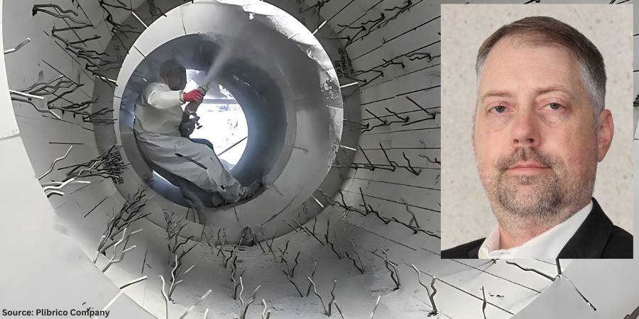
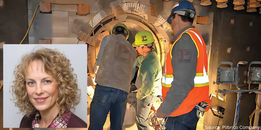
The faster the refractory installation, maintenance or repair, the more efficient and, by extension, profitable it is to the company, as savings fall to the bottom line. In this Technical Tuesday installment, Roger Smith, director of technical services at Plibrico Company, LLC, examines the challenges of insulation systems, taking a closer look at ultra-lightweight refractory gunite as a fast, flexible solution to controlling heat.
This informative piece was first released inHeat Treat Today’sFebruary 2025 Air/Atmosphere Furnace Systems print edition.
Manufacturers that rely on industrial grade furnaces, boilers and incinerators to produce their quality products are always looking for ways to improve. It is how they stay relevant and, more importantly, profitable. But you don’t get better just by desiring it. You need to identify better ways to get things done and introduce risk-neutral change to current operational processes. By some estimates, inefficient processes can reduce a company’s profitability by as much as one third.
Given refractories’ importance in safeguarding an operation’s multimillion-dollar thermal-processing equipment, and to avoid unscheduled downtime, it is smart business to have a sustainable maintenance and repair process in place. When a refractory situation does arise, the more proficient the process solution the better.
Controlling the Heat
Click the image above to read Roger Smith’s column on extending the life of refractory linings.
Furnace design is largely about controlling heat to maximize energy efficiency. An energy source — whether that is gas, coal, wood or electricity — is used to heat the furnace, and the furnace lining is designed to keep that heat inside the furnace. There are other factors to be considered, such as the environment inside the furnace, whether there is any abrasion or chemical interactions, or whether the furnace maintains a steady state temperature or undergoes temperature cycles. Regardless of what considerations have to be made for the hot-face lining, an insulation package must be used to reduce fuel consumption and control the cold-face temperature.
There are a large variety of insulation packages and materials that can be used in furnace design. Insulation comes in the form of board, fiber, brick and castables. Each type of insulation comes with its own sets of considerations, such as insulation value, installation method and cost. When considering the insulation package for the vertical wall of a furnace, support must also be considered because the insulation is expected to stay where it is placed and not slump over time. There also must be a means of connecting the hot-face working lining to the furnace structure to provide support. This is accomplished with an anchoring system that connects to the furnace shell and penetrates some distance into the dense hot-face working lining.
Anchoring Systems Challenge Insulation Installations
Anchors are considered to be the bones of a refractory installation and have several functions. They hold the refractory to the wall to keep it from falling in. They also prevent wall buckling due to the internal thermal stresses created by high temperatures. And, to a lesser degree, anchors can also help support the load of the refractory weight.
The anchoring system, however, can present big challenges when installing or maintaining the insulation. In most furnace applications, anchors are first welded directly to the furnace shell. Next, the insulation package is installed and finally the working lining. With anchors sticking off the furnace shell, installing insulation can become a challenge.
Fiber insulation in the form of blanket can be pressed into the gaps between the anchors, but it is important that the insulation remains in place during the life of the furnace. Industrial furnaces tend to vibrate, either from use of combustion or exhaust blowers or other process equipment. This constant vibration can cause fiber insulation to slump and lead to hot spots in the furnace wall due to the lack of insulation.
Figure 1. Anchoring systems are installed before refractory insulation and can pose challenges.
Insulation board is rigid enough to support itself on its end and can be found in a variety of densities and thicknesses to obtain the required insulation value. However, insulation board typically comes in sheets that will have to be cut to fit around the anchors. This can result in a significant amount of manpower and a significant amount of time in a furnace installation. The downtime of an industrial furnace can be costly, which often results in tens of thousands of dollars per hour in lost profits. For this reason, companies try to minimize the time spent rebuilding a furnace. Fewer man hours on a rebuild also tends to reduce the overall cost of the project.
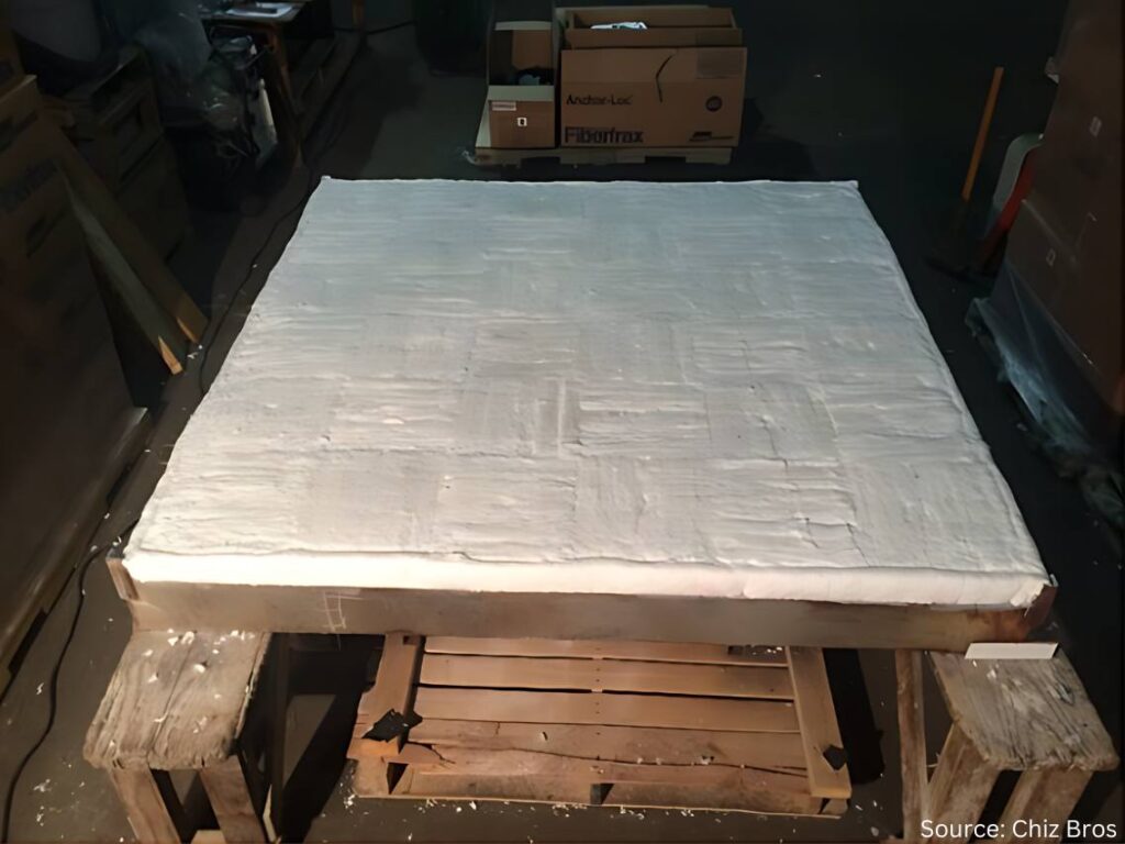
Ultra-lightweight refractory gunites offer a means of installing a large amount of insulation in a relatively short period of time. A gunite is a monolithic refractory castable that is pumped dry through a hose under pressure and is mixed with water at the nozzle. Once the wet castable impacts the surface, it stiffens quickly to avoid slumping and hardens as it dries. This means that the gunite could be installed over the anchors with minimal time. The installer only needs to wrap the end anchors with masking tape to keep them clean for the working lining.
Figure 2. Cold-face and heat storage/loss graph for a production furnace
Distinct Differences in Refractory Gunites
Ultra-lightweight castables are a sub-set of the lightweight castables category but with a very important difference: density. For example, the average lightweight castable with a maximum service limit of 2400°F typically has a density of about 80–90 pcf (pounds per cubic foot). By comparison, ultra-lightweight castables with a maximum service limit of 2400°F will have a density of about 25–30 pcf.
This important distinction comes into play when looking at insulation thickness and calculating cold-face temperature. At the stated densities in a furnace operating at 2000°F, it would take nearly three times more lightweight castable than an ultra lightweight castable to achieve the same cold-face temperature — making many ultra-lightweight castables perfect for insulation and most lightweight castable refractories impractical to use as part of the total insulation package.
Ultra-lightweight castables that achieve final densities of 25–30 pcf while offering service temperatures above 2400°F are available through various refractory manufacturers. One such product, Plicast Airlite 25 C/G (aka Liquid Board) from the Plibrico Company, is designed to be installed via casting or gunite using conventional gunite equipment. With low thermal conductivity and thermal-shock resistance, this material is durable and quick to install. It also has advantages over insulation board, which has a labor intensive installation process of cutting around all the welded anchors, and fiber insulation, which can experience frequent hot spots due to slumping insulation. With an ultra-lightweight, Liquid Board-type of castable, it is possible to attain required insulation values and extended lining life with the installation speed of a refractory gunite.
Working With, Not Against, the Anchoring System
Let’s consider a real-life production furnace operating at 2000°F with a simple 9-inch refractory lining consisting of six inches of dense refractory and three inches of insulation. For comparison, we will assume an ambient air temperature of 81°F and eliminate any effects of exterior wind velocity. The dense refractory working lining for these examples is Pligun Fast Track 50, a 50% alumina, 3000°F-rated refractory gunite.
As seen in Figure 2:
Using three inches of ceramic fiber blanket at a density of 6 pcf, a cold face temperature of 252°F can be achieved.
Using three inches of insulation board at a density of 26 pcf, a cold face temperature of 247°F can be achieved.
Using three inches of an ultra lightweight gunite such as Plicast Airlite 25 C/G with a maximum service temperature of 2500°F and assumed density of 25 pcf, a cold-face temperature of 262°F is expected.
The calculated difference in cold-face temperature between insulation board and the ultra-lightweight gunite is 15°F, but the difference in installation time savings could be multiple shifts.
Figure 3. Ultra-lightweight gunite is quickly applied over anchors with standard equipment.
The cost of downtime can be incredibly high for any manufacturer, especially since downtime can result in a series of costs and losses (both tangible and intangible), including production, labor, replacement costs, product losses and, if unexpected, reputation damage. Industry resources estimate downtime can cost thermal processing companies between $250,000 and $1 million per hour. When multiplied over several shifts, this could mean millions of dollars in downtime costs. Not to mention that labor is a major contributor to the overall cost of a refractory project. The quicker the refractory installation, the less downtime and the more profitable the company.
For example, in an approximately 750-square-foot round duct application (cylinder) with anchors already installed, on average, installation of four inches of the different insulation types can be estimated at:
Fiber Insulation — 137 total labor hours, or ~5.5 square feet/hour
Insulation board — 288 total labor hours, or ~2.6 square feet/hour
Ultra-light gunite/Liquid Board — 80 total labor hours, or ~9.4 square feet/hour
The quick and easy installation of the ultra-light gunite/Liquid Board represents an average estimated financial savings in downtime of between $35 million and $130 million — savings that drops directly to a company’s bottom line. The time compression of installing gunite also holds an added advantage for the insulation installer because labor hours can come with a premium price tag and can sometimes be in short supply. All of this makes the ultra-lightweight gunite solutions an excellent choice to minimize downtime and rebuild costs while meeting the furnace design criteria.
Conclusion
Manufacturers that rely on industrial-grade furnaces, boilers and incinerators to produce their quality products are constantly looking for ways to reduce costs, increase profits and improve efficiencies by looking at and introducing risk-neutral change to current processes. Maintaining efficiency and avoiding unscheduled shutdowns of heat processing equipment requires maintenance. Selecting quality materials and risk neutral installation processes that minimizes maintenance completion times can help companies become more efficient.
About the Author:
Roger M. Smith Director of Technical Services Plibrico Company, LLC
Roger M. Smith, a seasoned professional in the refractory industry, is the director of technical services at Plibrico Company, LLC. With a master’s degree in Ceramic Engineering from the University of Missouri — Rolla, Roger has over 15 years of experience in the processing, development and quality assurance of both traditional and advanced ceramics. He has a proven track record in developing innovative ceramic formulations, scaling up processes for commercial production, and optimizing manufacturing operations.
The Heat Treat Doctor® has returned to offer sage advice to Heat Treat Today readers and to answer your questions about heat treating, brazing, sintering, and other types of thermal treatments as well as questions on metallurgy, equipment, and process-related issues.
This informative piece was first released in Heat Treat Today’sFebruary 2025 Air/Atmosphere Furnace Systems print edition.
People often ask two fundamental questions related to normalizing. First, is it necessary? Second, just what and how important is a “still air” cool to the end result? Let’s learn more.
Why Normalize?
Contact us with your Reader Feedback!
Normalizing is typically performed for one or more of the following reasons:
To improve machinability
To improve dimensional stability
To produce a homogeneous microstructure
To reduce banding
To improve ductility
To modify and/or refine the grain structure
To provide a more consistent response when hardening or case hardening
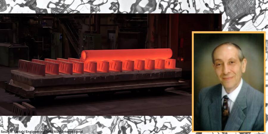
For example, many gear blanks are normalized prior to machining so that during subsequent hardening or case hardening dimensional changes such as growth, shrinkage, or warpage will be better controlled.
Normalizing imparts hardness and strength to both cast iron and steel components. In addition, normalizing helps reduce internal stresses induced by such operations as forging, casting, machining, forming or welding. Normalizing also improves chemical non-homogeneity, improves response to heat treatment (e.g., hardening), and enhances dimensional stability by imparting into the component part a “thermal memory” for subsequent lower temperature processes. Parts that require maximum toughness and those subjected to impact are often normalized. When large cross sections are normalized, they are also tempered to further reduce stress and more closely control mechanical properties.
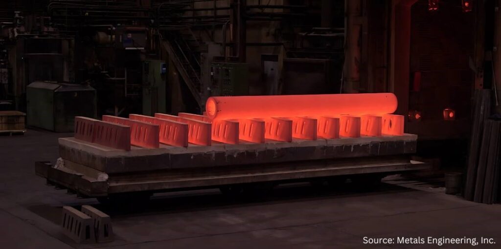
Large paper roll normalized in a car bottom furnace and cooled (due to its mass) using the assistance of a floor fan.
Soak periods for normalizing are typically one hour per inch of cross-sectional area but not less than two hours at temperature. It is important to remember that the mass of the part or the workload can have a significant influence on the cooling rate and thus on the final microstructure. Thin pieces cool faster and are harder after normalizing than thicker ones. By contrast, after furnace cooling in an annealing process, the hardness of the thin and thicker sections is usually about the same.
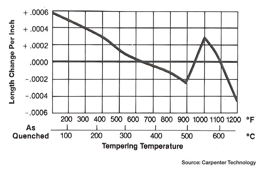
Micrograph of medium-carbon AISI/SAE 1040 steel showing ferrite grains (white etching constituent) and pearlite (dark etching constituent). Etched in 4% picral followed by 2% nital. (Bramfitt and Benscoter, 2002, p. 4. Reprinted with permission of ASM International. All rights reserved.)
When people think of normalizing, they often relate it to a microstructure consisting primarily of pearlite and ferrite. However, normalized microstructures can vary and combinations of ferrite, pearlite, bainite, and even martensite for a given alloy grade are not uncommon. The resultant microstructure depends on a multitude of factors including, but not limited to, material composition, part geometry, part section size, part mass, and cooling rate (affected by multiple factors). It is important to remember that the microstructure achieved by any given process sequence may or may not be desirable depending on the design and function of the component part.
The microstructures produced by normalizing can be predicted using appropriate continuous cooling transformation diagrams and this will be the subject of a subsequent “Ask The Heat Treat Doctor” column.
In this writer’s eyes, industry best practice would be to specify the desired microstructure, hardness, and mechanical properties resulting from the normalizing operation. Process parameters can then be established, and testing performed (initially and over time) to confirm/verify results.
In many cases, the failure of the normalizing process to achieve the desired outcome centers around the lack of specificity (e.g., engineering drawing requirements, metallurgical and mechanical property call outs, testing/verification practices, and quality assurance measures). Failure to specify the required microstructure and mechanical properties/characteristics can lead to assumptions on the part of the heat treater, which may or may not influence the end result.
“Normalizing is the heat treatment that is produced by austenitizing and air cooling, to produce uniform, fine ferrite/pearlite microstructures in steel … In light sections, especially in alloy hardenable steels, air cooling may be rapid enough to form bainite or martensite instead of ferrite and pearlite.”
What Is Normalizing?
The normalizing process is often characterized in the following way: “Properly normalized parts follow several simple guidelines, which include heating uniformly to temperature and to a temperature high enough to ensure complete transformation to austenite; soaking at austenitizing temperature long enough to achieve uniform temperature throughout the part mass; and cooling in a uniform manner, typically in still air” (Herring, 2014).
It is also important to remember that normalizing is a long-established heat treatment practice. As far back as 1935, Grossmann and Bain wrote:
Normalizing is the name applied to a heat treatment in which the steel is heated above its critical range (that is, heated to make it wholly austenitic) and is then allowed to cool in air.
Since this is one specific form of heat treatment, it will be realized that the structure and mechanical properties resulting from the normalizing treatment will depend not only on the precise composition of the steel but also on the precise way in which the cooling is carried out.
The term ‘normalizing’ is generally applied to any cooling ‘in air.’ But in reality, this may cover a wide range of cooling conditions, from a single small bar cooled in air (which is fairly rapid cooling) to that of a large number of forgings piled together on a forge shop floor … which is a rather slow cool, approaching an anneal. The resulting properties in the two cases are quite different.
In plain carbon steels and in steel having a small alloy content, the air-cooled (normalized) structure is usually pearlite and ferrite or pearlite alone … More rapid cooling gives fine pearlite, which is harder; slow cooling gives coarse pearlite, which is soft. In some few alloy steels, the normalized structure in part may be bainite.
The hardness of normalized steels will usually range from about 150 to 350 Brinell (10 to 35 Rockwell C), depending on the size of the piece, its composition and hardening characteristics.
Importance of Defining Cooling Rate
In 2005, Krauss underscored the importance of defining cooling rate when he wrote: “Air cooling associated with normalizing produces a range of cooling rates depending on section size [and to some extent, load mass]. Heavier sections [and large loads] air cool at much lower cooling rates than do light sections because of the added time required for thermal conductivity to lower temperatures of central portions of the workpiece.”
Microstructures Created by Normalizing
The microstructural constituents produced by normalizing for a particular steel grade can be ferrite, pearlite, bainite, or martensite. The desired microstructure from normalizing adds an important cautionary note, as addressed by Krauss in STEELS (1990 and 2005), namely: “Normalizing is the heat treatment that is produced by austenitizing and air cooling, to produce uniform, fine ferrite/pearlite microstructures in steel … In light sections, especially in alloy hardenable steels, air cooling may be rapid enough to form bainite or martensite instead of ferrite and pearlite.”
Next time: We define a “still air” cool and look at the state of normalizing in North America.
Practical Data for Metallurgists, 17th ed. TimkenSteel.
Totten, George E., ed. Steel Heat Treatment Handbook, vol. 2, 2nd ed., CRC Press, 2007. 612-613.
About the Author
Dan Herring “The Heat Treat Doctor” The HERRING GROUP, Inc.
Dan Herring has been in the industry for over 50 years and has gained vast experience in fields that include materials science, engineering, metallurgy, new product research, and many other areas. He is the author of six books and over 700 technical articles.
In this Heat TreatRadioepisode, Mark Rhoa, Jr. from Chiz Bros, a company specializing in ceramic fiber products, discusses insulation with host Doug Glenn. Mark focuses on the benefits of ceramic fiber in industrial applications. The conversation covers decarbonization, the importance of insulation and thermal shock resistance, the shift to electrically heated modules, and practical maintenance tips for ceramic fiber-insulated furnaces.
Below, you can watch the video, listen to the podcast by clicking on the audio play button, or read an edited transcript.
Doug Glenn:I want to welcome our guest today: Mark Rhoa Jr. from Elizabeth, Pennsylvania, near Pittsburgh. Mark’s been involved with the industry for quite a while with Chiz Bros, our sponsor for today. Mark is also aHeat TreatToday40 Under 40honoree from the Class of 2021. And, Mark, could you tell me who started your company — your dad or your dad and his brother? I don’t know the history that well.
Mark Rhoa: My dad actually joined the company in ‘97, but when he joined, Chiz Bros. had been around for a good 30 years or so. It was started by the Chiz brothers originally: Al, Ray, and John Chiz. As they got older and some of them moved on from the company to retire, my dad took over the company in 2014, and that’s when I came on board.
I’ve been here about ten years. And Ray Chiz Jr. just recently retired; he is one of the original owners’ sons who was working here running our warehouse. He’s the last with the Chiz name to work here. We say that the Chiz haircut is kind of what I’ve got going on. You can know by the haircut there’s a lot of Chiz’s still working here, and you might even be an honorary.
Doug Glenn: I can be an honorary, for sure. I don’t have enough on the side.
Chiz has been around for 50 some years doing specialty solutions for refractory applications in the metals, power, glass, and ceramics industries. And you guys deal with multinational companies as well as the small Ma and Pa shop furnace manufacturers or heat treaters/thermal processors, a pretty good mix. You’ve got great customer service, reasonable pricing, and quick delivery. And I know you and I have talked about how you guys pride yourselves on having a lot of stuff in stock. And finally, you guys have your Pittsburgh location and are also in Detroit, which is a relatively new addition, right?
Mark Rhoa: Yeah, about two years ago we opened up a Detroit warehouse. We’ve always had some good clients up that way. You’ve got to have some boots on the ground to be super effective. I say to get the easy orders you’ve got to have the stuff on the ground to get the hard orders, which are the phone calls at 5 o’clock on a Friday saying, “Hey, we need to pick this up because the furnace is down.” And we didn’t have that opportunity to improve our customer service up there before opening that location.
We try to punch above our weight to compete with the big guys on pricing. We make sure we’re always still answering the phone.
Doug Glenn: It makes a huge difference when you’ve actually got people answering the phone.
My understanding is that you provide castables, fibers, brick, etc. But today we want to hone in a little bit on ceramic fiber.
Mark Rhoa: Ceramic fiber is the big portion of our business. We’re one of the biggest Unifrax (Alkegen) ceramic fiber distributors in the country. So, a lot of what we do is being driven by ceramic fiber products we supply. We still can supply castables, bricks, and everything in between. But ceramic fiber drives the ship for us.
What Is Ceramic Fiber? (04:58)
Doug Glenn: Let’s talk about that. Most of our listeners are folks with their own in-house heat treat. But let’s assume we’ve got some people watching that don’t know some basics.
Tell us about ceramic fiber: What is it? How is it made? What are we using it for?
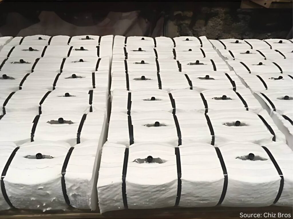
Mark Rhoa: I describe it to people who may not know much about it by comparing it to the Pink Panther insulation that people may recognize up in their roof or in their walls. Ceramic fiber is white, but picture that insulation for 2300°F. That’s what ceramic fiber is, and it’s a form that we sell the most of right now.
Ceramic fiber
You can take that and cut gaskets out of it. You can form it into hard boards through a vacuum forming process. You can take it folded into what we call ceramic fiber modules; your furnace probably has modules in it if it’s a traditional gas-fired or electric furnace. Ceramic fiber products typically aren’t used on the vacuum side of things. People with all vacuum furnaces are probably not going to be using ceramic fiber. There are cloths that are ceramic fiber based as well. There’s a bunch of other ways it’s used.
Ceramic fiber is made of a blown, spun glass. Essentially what you’re doing is dropping the liquid aluminum silica mixture, and it gets blown or blown and spun at super high temperatures. I’m not going to get into the details of the differences there, but whether the stream is blown or is spun on wheels will determine the tensile strength of blanket.
In the grand scheme of things, what you’re doing is collecting all that fiber and getting it onto a mechanism that’s moving along a conveyor belt. Then it’s getting needled from each side to interlock the fibers to make a 26” wide blanket. It’s going to be trimmed off an inch when it goes through, and at the end you have a 24” wide x 1” thick, 8-pound density roll coming out.
Those densities can vary based on how much fiber is going into it. It’s pounds per cubic foot. But when you’re using a 1” thick piece, it’s divided by twelve from a weight standpoint. The fiber you’re needling in there determines the density.
And there are slightly different chemistries for 2300°F, 2600°F, and the most expensive would be 3000°F polycrystalline. The process to make that is a little bit different, too.
But most people are probably more interested in what we’re doing with it. What’s the Chris Farley line in Tommy Boy? We’ll keep it PG, but “take a butcher’s word for it” — take our word for it; it’s made the right way.
Now we can get into how it’s actually used.
Doug Glenn: It’s basically like insulation in your house, like you said. That’s probably the best description of it for people that need to know. But it can obviously go to a much higher temperature.
In an industrial setting, why would you use fiber versus a castable or brick?
Why Fiber? (08:28)
Mark Rhoa: Ceramic fiber is a great insulator. We’ll probably get into why a better insulator is important for decarbonization efforts and things like that.
It’s certainly a better insulator than castables, easy to install, and easy to use. The main reason it’s preferred is for its insulating value and ability to have varying temperature ranges, which you can certainly do with castables and brick.
But to put brick in a wall 12” thick, for argument’s sake, you will need four layers of 3” brick on there. With ceramic fiber, you can take one 12” x 12” module, shoot it onto the shell, attach it, and be good to go from there.
The main thing would be longevity and stuff like thermal shock value. One of the things you have to worry about with castables and brick — maybe not as much with IFB but standard brick — is the heat cycling. Heat treat furnaces are a great example of that.
That door is opening up a lot, so the air is coming in there. People probably see it in their furnaces. The castable is going to want to crack because it’s not designed for thermal shock like ceramic fiber is.
There are certainly applications that you wouldn’t want to use ceramic fiber for. If you’re looking at a traditional heat treat furnace, it depends on how the load is supported: If the floor is the refractory, it is actually supporting the load, and you’re going to want some sort of brick, some sort of castable. Fiber is going to be soft, compressed, and get beat up. You can’t necessarily put it everywhere, but there are areas where it may be up for debate on.
You can use a brick or you can use fiber in the wall. Traditionally, you’re going to use fiber for the insulated value, thermal shock value, installation, and weight; it’s a lot lighter.
A lot of heat treating furnaces are small compared to the massive furnaces in steel melting. They’re going to ship heat treating furnaces. With ceramic fiber, a 12” x 12” fiber module, 12” thick, weighing roughly 12–14 lbs. is 5–10x lighter than brick or castable.
Repairability (10:51)
Doug Glenn: How about addressing the repairability issues between castable and brick and fiber?
Mark Rhoa: Fiber, especially if you’re getting into higher temperatures, can have some shrinkage to it. But you’re able to repair fiber a lot easier. If you wreck a little bit of fiber, you can get in there and get it repaired quickly. With a brick or castable everything’s tied together as either a monolithic piece or a bunch of bricks that are connected, it can start to become a house of cards scenario where you pull and one goes down then everything goes down.
Doug Glenn: It’s like a Jenga game. You pull that brick out on the bottom and what happens?
Figure 2. “You don’t want to pull out the wrong brick.”
Mark Rhoa: Yeah, you don’t want to pull the wrong brick.
Doug Glenn: You already mentioned the temperature ranges we’re talking about. The standard bottom temperature is 2300°F; the fibers are good up to 2300°F. Then you’ve got 2600°F and then 3000°F. Is that roughly the breakdown when you’re looking at fibers?
Mark Rhoa: I don’t know why they ended up doing this, but for 2300°F ceramic fiber, realistically you only want to use it to 2150°F. That goes along with the shrinkage curve of it. I forget the exact number, but I think it’s like in 24 hours, you get less than 3% shrinkage. Typically, the rule of thumb is that you don’t want to use that full temperature range; you want to give yourself 150°F of cushion to be safe. It will still have shrinkage after that up to that temperature.
I don’t know who ever thought of that; it was probably some genius marketing guy to get a little extra.
Fiber Shrinkage (12:57)
Doug Glenn: You’ve mentioned shrinkage a couple different times. Why does that happen with ceramic fiber? And how does that impact installation?
Mark Rhoa: When ceramic fiber hits its operating temperatures, it shrinks up. On the chemistry side, I don’t have an answer there. But we factor in compression to help alleviate when something shrinks. It’s already pushing out against something. It still keeps its resiliency (it wants to pop back out), and that’s factored into every design.
If you’re doing 12” modules, you’ll have a batten strip between them. That makes up for some of the shrinkage that may come where there’s not compression. Any sort of design we would do, or probably anyone would do, is going to factor in shrinkage. You don’t want to just put something in there, and when it shrinks, it leaves a gap. You want to make sure you have something in there that’s going to fill that gap; and that’s typically for modules.
Now if you’re getting to a low temperature, we’re talking about a furnace at 1200°F, you’re not going to have to worry about shrinkage. Even in some of those furnaces, you’ll see designs we call wallpaper — a pin’s exposed and you’re layering on top of it. You’re just kind of overlapping gaps, but you’re not going to have any shrinkage there, so you don’t really have to worry.
Figure 3. Avoiding gaps when shrinkage occurs
Doug Glenn: There is one question I did want to ask you when we were talking about the different temperature ranges of 2300°F, 2600°F, and 3000°F. Are the chemistries between those different?
Mark Rhoa: They’re all alumina silica based. 2300°F is like 50% alumina and 40% silica. They’ll typically inject some zirconia in it, maybe around 15% zirconia. That gives it the extra boost. Alumina is what drops down.
We don’t want to get into every example, but it does have a lower aluminum content. Sometimes in aluminum melting you can get some flexing because there’s zirconia in there, so you need to know the exact application.
And then the polycrystalline, what people call the 3000°F, would be 72% alumina. And that’s made in a calcined process. The 72% alumina is the key factor.
You can also have super high aluminum blankets. Saffil® is the typical brand name. And that’s a 95% plus alumina. That’s for high hydrogen atmospheres, stuff where there’s bad attacking, bad off gassing. The alumina is usually more resilient to that. Some aerospace applications have that stuff spected in for effectiveness and also because they probably have government money. Why not pay for the highest quality, most expensive thing, right?
Electric Element Modules (18:32)
Doug Glenn: You mentioned modules before, but I want to take a little bit of a different angle. The modules you were talking about have no type of heating element in them. They’re just simply the insulating modules that you put on the side of the wall, side by side, maybe alternating the orientation. But what I want to talk about are electric element modules. Can you describe what those are and why you are using them? And maybe hit on the decarbonization or electrification element of those?
Mark Rhoa: Traditional fiber modules are used in a gas furnace, even an electric furnace that may be heated by glow bars or radiant tubes or something like that. That’s going to have a similar penetration there.
One of the systems we call our ELE system. I’d say in the last two years we’ve probably had as many inquiries or conversations about going to these electrically heated modules than we have in the past 5–10 years combined. A lot of that has to do with companies wanting to get away from gas, or they’ve got pressures for different environmental or cost saving reasons.
What we’re doing with that is hanging the elements on the ceramic fiber module. And when they show the pictures of this one, there’ll be one in there. But that allows us to do a modular system where they can get a lot of power on those walls, and it lets us keep a lot of the same insulating value from using modules without having to use brick or a super heavy element in the sidewalls for support.
Electric Element Modules
When someone says we’re putting this many BTUs of gas; here’s the load, size, weight. We do the electric calculations to see how many kilowatts of power we need to pump into this furnace and elements in order to heat something up just like you would do with gas.
And rest assured, someone a lot smarter than me does those calculations. I’m just a pretty face that gets to sell them. But this is something that we’re seeing a lot of. There’s a big push coming from the government and boards of directors.
Doug Glenn: It’s going to help companies reduce their carbon footprint if that is their desire.
I have a question for you about those and specifically about installation. If every module needs a power source, do you have to punch a hole in the furnace wall for every module, or can you interlink them and only have one power source at the end of the chain?
Mark Rhoa: Good question. I didn’t do a good job describing that, but the modules will still go in just like a regular module. They actually have an extra set of ceramic tubes in them. When we do our design, we know where the elements are going to be hung.
If you have a 10-foot wall, you’re not going to have ten 1-foot pieces of element. You’re going to have an eight foot string of elements along that wall, and they will be hooked into the loops. One end of the hook will go on a loop, the other end will go on the ceramic tube that’s inside the module.
If you have a 12’ x 12’ high wall, and you may have a 10’ element in there, you’re probably only going to have four penetrations, maybe more. It’s not going to look like Swiss cheese. They’re going to be linked together.
These are all based on the number of zones in a furnace, too. Some super high aerospace applications are going to have everything super fine tuned just like it is with burners. If you think about how certain applications require way more precision and control over burners, the same thing can be true for these elements, too. The more precision and control you need, the more complicated it’s going to be just like it is with burners.
Before you hang the elements, you could look in that furnace and it would look just the same as a regular gas-fired furnace without the burners. Then you start hooking the elements on the walls. And the pictures of it are helpful.
If anyone has seen Home Alone, he goes into his basement and his furnace is shooting out all the flames. If you walk into a plant and can see that, getting that to seal will prevent heat from leaving.
Mark Rhoa
Furnace Doors (23:52)
Doug Glenn: When I think about ceramic fiber (which you don’t often see it inside a furnace if the door is closed), but a lot of times you’ll see it jammed in around the doors. To me it doesn’t look like that’s the way it’s supposed to be. So, doors are an issue, right? Can ceramics help with that?
Mark Rhoa: In heat treating furnaces, the temperatures aren’t totally crazy like forging furnaces where there’s a lot of shrinkage so they’re replacing it all the time. In heat treat, the temperature is lower. The main wear and tear items we see when we’re working on a repair with a client are around the doors because they’re getting the mechanical abuse of constantly changing. In some of the decarbonization talks I’ve attended and given at trade shows, we’re really looking at ways to save heat. Just making sure your door is sealed properly can do wonders.
If anyone has seen Home Alone, he goes into his basement and his furnace is shooting out all the flames. If you walk into a plant and can see that, getting that to seal will prevent heat from leaving.
You hear all these decarbonization talks, you see all these millions of dollars being thrown around, and, really, you can make a huge difference on a shoestring budget by simply making sure your door is sealing the way it’s supposed to seal.
If you can see the heat coming out, it’s like dollars flying out of your furnace on a game show. You’d have people lined up for that every day of the week.
So you hit the nail right on the head there. A really small, easy way to make a calculated decarbonization effort is making sure you have a door plan or you’re changing it.
It’s the same thing with tuning burners. Little tunes to a burner can save tons of gas and tons of CO2.
Figure 5. Heat leakage from doors needing maintenance
Doug Glenn: Making sure you’re maintaining good flame curtains on a continuous furnace, all that stuff just keeps the heat from coming out.
Did I see correctly that you guys do door repairs?
Mark Rhoa: We’ll do door repairs in our own shop. If someone ships a door to us, we’ll do the realigns there. About 20 years ago, we stopped having our outside contracting arm. Now we’re not doing any of the fieldwork. But we do realign doors in our shop.
Fiber is pretty easy to work with. Door perimeters are something that can easily be done by someone’s own maintenance crew. Maybe they’ll need one of our sales guys there making sure they do it right the first couple times. But it’s not a hard thing to do. If you have a 12 inch module perimeter, switch those 40 modules out once a year and you’ve got fresh gas savings.
Ceramic Maintenance (27:07)
Doug Glenn: Let’s shift gears a bit and talk about typical maintenance of ceramic-insulated furnace. What do we need to be careful about? Any tips you can offer?
Mark Rhoa: There’s another really affordable thing you can do. You can probably sometimes see this if you have a hot spot where paint’s chipping off or melting or if you have a temperature gun you can find those hot spots. If you see heat on the outside, then you’re typically going to see some sort of crack or gap on the inside. Make sure you have scheduled maintenance downtime with your furnace and stuff in any of those cracks.
If you’ve got a really big furnace or a continuous furnace, roller hearth, furnace type thing, the roll seals are some of the areas where you’re going to end up losing a lot of heat because there’s more wear and tear there. There’s just more opportunity for expansion and contraction.
We do have ceramic pumpable products. We call it liquid ceramic fiber for when there’s a hot spot on a furnace, it’s a big one, and you can’t get in there, you can drill a little hole on it, pump it in from the backside, and fill that up. You don’t want to start making your furnace Swiss cheese and poking holes.
It can be a quick stopgap. If you can’t get inside the furnace, fill it in from the backside, too. Because you don’t want those hot spots to grow and cause problems. You don’t want them to get to the hardware.
Then you may have a module where the hardware gets too hot in the backside and the module ends up falling in. That’s one scenario. You can get out ahead of it by filling some of those gaps.
For a refractory on the hearth, too, if you don’t want to replace a hearth you can find a refractory contractor to come in and (if you have a big furnace) spray gunite over the hearth to fix any gaps or cracks.
Doug Glenn: That’s more for castable, though?
Mark Rhoa: Yeah. On the fiber side of things, you’re looking for hot spots.
Doug Glenn: The takeaway is to make sure you’re taking regular thermal imaging of your shell of the furnace. If you’re noticing some hot spots, it’s time to investigate.
Mark Rhoa: If you have a lot of furnaces, you can get a thermal imaging gun for a couple hundred bucks and really [keep an eye out].
An even bigger deal are the doors. It will blow your mind if you look at the temperatures on a fresh door seal versus an old one. Have a temperature gun to justify to your bosses. “Hey, we realigned this, and it is 150°F. This time last year it was 250°F–350°F degrees.” Common sense can tell you we’re losing more heat when it’s like that.
Concerns with Free Floating Fiber (30:20)
Doug Glenn: Can you address the concern that some furnace users have regarding free floating fiber, especially in furnaces where there’s high velocity airflow?
Mark Rhoa: Talking about the benefits of fiber versus brick and castable, one of the benefits of the hard refractory is it does better with high velocities. Patriot furnaces may have a fan in there. Typically, they’re not getting high enough where we need to worry. You can put coatings on the fiber or rigid dyes or things like that to harden them.
But from a health and safety perspective, anytime you’re working with fiber you want to make sure you’re wearing a mask. They have warning labels on them. It’s not like it was back in the day. I’m not allowed to say the “a” word [asbestos]. So there are not worries like that anymore, either. But refractory ceramic fiber still does have a warning label on it.
We do have body size soluble fiber. Alkaline earth silica (AES), non RCF fiber, a bunch of fancy names, are more prevalent in Europe because of their rules. California’s got a lot of rules, too….
But we do supply that as well. It doesn’t have any sort of warning labels on it.
Obviously, when you’re working with it, you want to wear a mask because dust in general isn’t good. But it’s naturally soluble for your body.
It’s not quite as strong. It can have more shrinkage at lower temperatures. But it’s best to talk with somebody and understand what the right product is to use. Things can be a little worse, but there is a slight move in the direction of body soluble fiber because there are no warning labels on it. But it’s not drastic.
Some of the similar concerns foundries have is with sand and airborne silica now. Technically, I guess going to the beach we’d have airborne silica, too. There’s justification to taking those precautions, but it’s certainly not all doom and gloom.
The ceramic fiber is essentially little glass beads, like a tadpole head and then there’s a fiber tail that interlocks.
Mark Rhoa
Doug Glenn: What I heard wasn’t so much a human safety issue. It was the use of ceramic blankets inside of an aluminum annealing furnace: If the fibers got airborne, they would come to rest on the coils and mess up the strip going through. And then you have contaminated coil or it’s marked.
Mark Rhoa: The issue with that is the shot on the fibers. The ceramic fiber is essentially little glass beads, like a tadpole head and then there’s a fiber tail that interlocks.
Fiber has come a long way. The shot content is way lower than it used to be. But it’s certainly a concern if that gets on a coil and then it goes through the rolling mill and you make a small dent in all the glass … yeah.
A lot of different things can be done for that. People put up cladding; people rigidize it to lock the fiber in.
There are definitely concerns for all the applications. Big aluminum homogenizing furnaces may have that. Traditional, smaller batch annealing furnaces may not.
It would be the same thing if a little piece of brick chipped off onto [indiscernible]. The worry with some of the fiber stuff is it’s obviously a lot smaller so you don’t get to see it.
Doug Glenn: It’s a lot more conducive. You can imagine the difference between a brick being hit with high velocity air and a fiber, you would just see the degradation of the fiber. A fiber ceramic blanket would go down quicker.
Induction at Chiz (35:20)
I have one other question for you about Chiz. Your company was one of our sponsors at our recent Heat TreatBoot Camp, and I was surprised when you had an induction coil on your table. If you don’t mind, address what it is Chiz is doing in the induction area?
Mark Rhoa: We were using the company down the road from us, Advanced Materials Science (AMS), to machine some of our fiber boards and bricks that were a little too complicated for what we had in-house at the time. They have some really good CNC equipment up there. The guy who owned AMS was looking to sell off that branch of his business. We had been one of his bigger clients, and we came to an agreement to it; it’s still out of the same building, same equipment, same guys that are doing all the good work.
We started getting in there and saw a lot of the induction heating equipment on the client list — a lot of those electrical plastics, high temperature plastics, electrical marinite and transite boards, which we got into a little bit in the Chiz Brothers world but didn’t fully dive into it because the temperatures are a little bit lower than what we’re dealing with on the ceramic fiber side of things.
It’s been really good for us. They’ve got great machining capabilities down there to machine some of these complex parts out of NEMA G10 and marinite and transite and all these terms that were relatively new to me when we bought them.
It’s really helped us at some of these trade shows because three types of furnace guys walk by: the gas-fired guy, he’s my best friend; the induction guy used to be like, “There’s not that much we can do with you.” Now, we can do a lot with them.
And then I’m still trying to figure out how I can be happy when the vacuum furnace guy walks by. That will be a different battle for a different day. I’m not trying to get into the graphite felt world. I probably just can’t be friends with everybody.
But it’s been good to get into the induction industry. It’s something that we’ve been growing over the last year or two because we hadn’t been engaged with people quite as much as we had.
Doug Glenn: Well, we’ll look for opportunities for you to be friends with the vacuum people. One thing I know from experience, Mark, you could be friends with anybody. I’m sure you can work it.
Mark Rhoa: I’ll try my best.
Doug Glenn: You’re doing good.
Thanks so much. I appreciate your time and appreciate you being here.
Mark Rhoa: Look forward to seeing you at the next event. For anyone watching, Heat TreatBoot Campwas great. Whether you’re a supplier or heat treater, it’s a good group of people bouncing ideas. It’s a crash course on a hundred different things in two days. I was there to sell stuff, but I learned stuff, too, which was an added bonus. I’d recommend it to anyone watching. It’s a good way to force yourself to get out of the office. I will definitely be back.
Attendees of the 2024 Heat Treat Boot Camp with the Heat Treat Today team Heat Treat Boot Camp Completion Ceremony: (L to R) Doug Glenn, Mark Rhoa, Thomas Wingens
About The Guest
Mark Rhoa Vice President Chiz Bros Eleanor Rhoa, daughter
In the heat treat industry, Mark handles Chiz Bros‘ relationships with various end-use customers as well as furnace manufacturers. Given the critical need for energy efficiency and uniform temperature throughout the heating process, Mark has been able to develop custom refractory and insulation solutions for customers to meet their complex needs. Through participation in the ASM’s Heat Treat Show, MTI’s Furnaces North America,Heat TreatToday’sHeat TreatBoot Camp, and IHEA’s Decarbonization SUMMIT, Mark has been supportive of the industry, but more importantly, has helped countless customers improve their thermal efficiency and profitability. Mark was recognized inHeat TreatToday40 Under 40 Class of 2021.
As this author notes, “Aluminum’s unique blend of lightness, strength, and purity makes it indispensable across various industries.” Especially for aerospace components, bonding aluminum alloy materials to achieve premium structural integrity is essential to keep pace with the demands of new component designs.
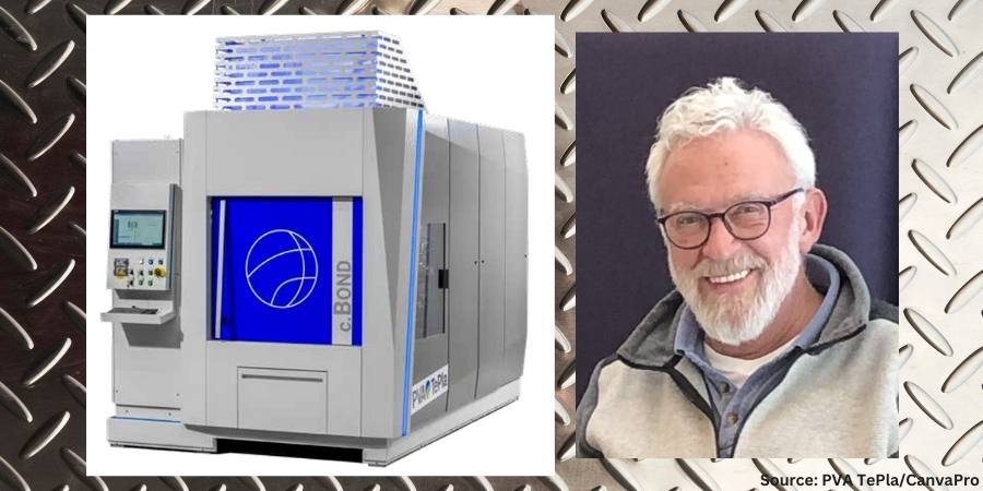
In this Technical Tuesday installment, Horst-Gunter Leng, product manager at PVA TePla discusses recent developments in diffusion bonding technology with increased bonding speed of aluminum and aluminum alloys by up to 50%, decreased energy use by 30%, and improved quality.
This informative piece was first released inHeat Treat Today’sFebruary 2025 Air/Atmosphere Furnace Systems print edition.
Background: Aluminum Innovations and Joining
Aluminum, and its broad family of alloys, is prized as a lightweight metal with high purity, strong structural integrity, high electrical and thermal conductivity, corrosion resistance, and a malleability that makes it easy to shape. In aerospace, its high strength-to-weight ratio is crucial for structural components. For semiconductor equipment, aluminum enables the fabrication of intricate, contamination free channels essential for gas and fluid flow, avoiding the impurities inherent in traditional joining methods like brazing or welding.
Many developments in high demand or high quality industrial sectors involve aluminum as one or more of the layers of metals that are bonded. Diffusion bonding is a joining method used to achieve a high-purity interface when two similar or dissimilar metals require superior structural integrity and a traditional brazing approach fails to yield optimum results. The process involves applying high temperature and pressure to metals mated together in a hot press, which causes the atoms on solid metallic surfaces to intersperse and bond, typically (but not exclusively) in vacuum furnaces.
Aluminum’s compatibility with diffusion bonding has allowed for the creation of complex cooling channels in high-power electronics, injection molds, and specialized heat exchangers — designs often impossible to achieve through conventional machining.
Unfortunately, the thermal conductivity characteristics of aluminum present a challenge for the traditional diffusion bonding process, which involves the application of radiant heat into the metal layers while in a vacuum furnace.
This article explores a new bonding technology that overcomes this challenge with a conductive heating method which more rapidly reaches bonding temperature.
Traditional Diffusion Bonding: Challenges with Aluminum
Figure 1. Depiction of a c.BOND machine
In the traditional diffusion bonding process, a vacuum furnace provides radiant heat to the surface of the part. Subsequently, the heat is conducted through the assembly and transmitted to the faying surface (i.e., surfaces in contact at the joint) where required. Aluminum excels at conducting heat, particularly at lower temperatures, making it ideal for applications requiring efficient heat dissipation, such as in electronics and automotive components. However, when radiation is the dominant form of heat transfer, particularly at relatively lower temperatures in vacuum below 1112°F (600°C), aluminum’s thermal conductivity is time consuming.
Aluminum’s high reflectivity poses a challenge in traditional diffusion bonding. It is like trying to heat a mirror with a spotlight — the energy is reflected away instead of being absorbed into the material using the traditional diffusion bonding process.
Diffusion bonding of aluminum requires superior temperature control throughout the process. To prevent overheating of the load, slow heating rates traditionally are applied, leading to long process times.
In addition, aluminum alloys have a narrow processing temperature range for successful bonding. When temperatures fall outside that critical temperature band, a poor bond is produced.
New Diffusion Solution with Conductive Heating
To overcome the existing challenges of bonding aluminum, a global manufacturer of both industrial furnaces and PulsPlasma nitriding systems alongside its partner initiated an extensive development program. The result was an innovative solution: integrating heating elements directly into the press platens. This approach speeds up the bonding process and significantly reduce enhances efficiency by directly transferring heat to the aluminum components.
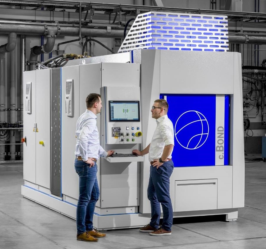
The culmination of this research and development is the c.BOND machine. The machine features a combination of direct conduction heating through the top and bottom platens, which are in contact with the assembly. This design ensures bi-directional homogenous heating and more precise temperature at the bonding interface where it is required.
The machine utilizes a hot-press tool with advanced software and feedback sensors to achieve micrometer-precise pressure control across the entire component surface. This ensures uniform bonding over large areas. Furthermore, the system allows for selective heating of specific areas, preventing unnecessary heat exposure to other parts of the component.
The high-vacuum atmosphere within the chamber eliminates contamination and prevents voids in the bonded joint.
With this machine, the time to heat the part to the ideal temperature for bonding is cut in half compared to traditional radiant heating. With less processing time required, the energy requirements are reduced by up to 30% as well. Multilayer stacking is also possible, which can further increase productivity.
With the size of components continually getting smaller in sectors like semiconductors and electronics, controlling the amount of time, and by extension heat, introduced into the part becomes more critical.
Horst-Gunter Leng
The technology demonstrates significant quality improvement of bonded aluminum components. It improves temperature homogeneity in the load by 70%, enhancing bonding across the entire surface. This method also improves the parallelism of parts by 50%, which enhances the accuracy of geometric dimensions, tolerances and product specifications.
As this new machine is commercially available for high-volume production, heat treaters can leverage this furnace technology alongside another unique feature that is incorporated within the system: proprietary automatic bonding software (ABP).
With the automatic bonding software, after parts can be placed in the furnace and a few parameters (such as the size of the bonding area) input, the software automatically calculates the optimum processing parameters. No specific diffusion bonding knowledge from the operator is required. The recipes can be modified according to the type of material being bonded, the thickness of the material, its surfaces and other factors. During the process, the software continuously monitors the process in real time and adjusts parameters accordingly.
Real-World Applications
A unit was installed at a national research facility in Germany, The Günter Köhler Institute for Joining Technology and Materials Testing (ifw Jena), an independent, non-university industrial research institution that conducts research in diffusion bonding, additive manufacturing, brazing, welding, laser processing, material science and other forms of bonding.
The system is compact, requires minimal maintenance, and enables high-volume production of aluminum components for diverse industries. Its benefits are being realized in aerospace, where it creates lightweight yet strong aircraft components. In the semiconductor industry, it provides a cleaner alternative to brazing, eliminating the risk of solder contamination. There is also growing demand for diffusion-bonded aluminum heat sinks, crucial for cooling high-power silicon carbide (SiC) electronics.
Figure 2. Example of the c.BOND machine
Diffusion bonding also has applications for conformal cooling. The concept is to bond layers of sheet metal that contain machined channel/microchannel structures. When combined, the channels provide a path for heat dissipation. Current applications include power electronics for effective heat management and rapid cooling of molds utilized in injection and blow molding processes.
With the size of components continually getting smaller in sectors like semiconductors and electronics, controlling the amount of time, and by extension heat, introduced into the part becomes more critical.
As the features of the internal channels become more miniaturized, it becomes even more important to control the heating during the diffusion bonding process to avoid any distortion in the part. Shortening the cycle time means introducing less heat into the part. This will facilitate creating parts with conformal cooling channels that have finer and finer features.
As mentioned earlier in this article, diffusion bonding is increasingly valuable for joining dissimilar metals, such as aluminum to steel or titanium. This allows engineers to design components and assemblies with the best properties of each metal. For example, one metal might offer superior corrosion resistance while the other provides greater strength. This “packaging” of dissimilar metals opens up new possibilities in design, particularly for overall weight reduction of design and enhancing performance in challenging environments.
When joining dissimilar surfaces, a liquid-phase diffusion bonding process is utilized, particularly when the bonding interface extends beyond R&D-sized samples. This often involves an interlayer of an alloy that typically melts at the faying surfaces. When the interlayer includes aluminum, the machine can deliver controlled heat to increase the bonding speed.
Conclusion
This new approach to diffusion bonding offers an alternative to the traditional method by circumventing the slow process of radiant heating structural assemblies in a vacuum environment. Although the technology in c.BOND is designed to improve the diffusion bonding of aluminum, it can be modified to the specific needs of the client and customized for the alloy, including copper, an alloy that has many applications in specialized heat exchanger and products used in the microelectronics industry. PVA TePla is exploring options to modify the machine to achieve even higher temperatures above the current maximum of 1472°F (800°C).
As diffusion bonding of aluminum gains importance across industries, contract manufacturers and design engineers must embrace the latest advancements to remain competitive. By adopting fast, energy efficient diffusion bonding technologies for aluminum and other materials, they can unlock higher production volumes, reduce costs, improve or achieve global sustainability targets, and increase profitability.
About the Author:
Horst-Gunter Leng Product Manager PVA TePla
Horst-Gunter Leng is the product manager for PVA TePla, a global manufacturer of industrial furnaces and PulsPlasma nitriding systems.
The Heat Treat Doctor® has returned to offer sage advice to Heat Treat Today readers and to answer your questions about heat treating, brazing, sintering, and other types of thermal treatments as well as questions on metallurgy, equipment, and process-related issues.
This informative piece was first released in Heat Treat Today’sJanuary 2025 Technologies to Watch print edition.
As a very young engineer, I vividly recall our company president had a statue of a three-headed elephant in his office. One head faced forward, one faced slightly to the right, one faced slightly to the left. The moral: looking backwards is not the path forward! Let’s learn more about what the heat treatment industry will look like by the middle of this century.
The Market
A number of market studies and economic forecast models suggest that the global heat treatment market will grow to between 130–150 billion U.S. dollars by no later than 2030 and to around 200–220 billion U.S. dollars by 2040, barring another significant or sustained global economic event. These forecasts assume several minor downturns in the economy of various countries and in manufacturing segments due to economic and geopolitical factors in the coming decades.
Heat Treatment Market Shift
Contact us with your Reader Feedback!
The most significant and fundamental shift that is and will continue is in the makeup of the heat treatment equipment segment of the North American market. What began in the late 1990s and early 2000s as a transition from older, long-established practices and processes to equipment capable of meeting the rapidly evolving demands of technological innovation will continue. Standardization (for cost containment), changes in manufacturing methods and methodologies, and environmental considerations are also fueling this change.
A demand for higher performance products, end-of-life expectations (in some but not all products), an emphasis on systems with single-piece flow or small batch productivity are just a few examples of this change. Other factors such as equipment obsolescence, the need for even higher manufacturing efficiencies, long term operator health and safety concerns, predictive (as opposed to preventative) maintenance, and adaptation to both the speed at which the manufacturing landscape is changing and the type of flexible equipment/processes reinforce these conclusions.
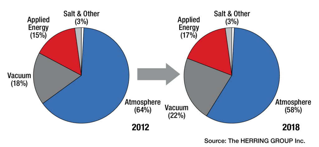
From an equipment standpoint, vacuum furnaces and applied energy systems are and will continue to experience rapid growth at the expense of more traditional atmosphere furnaces. Safety, open flames and emissions of any kind (NOx, CO2, particulates) are driving this change. As such, the dramatic reduction and control of greenhouse gases and the cooling of our planet by the mid-century will be metamorphic. This trend is not only expected to continue but to accelerate (Figures 1–2).
Figure 1. North American Industry by Equipment Segment, 2012–2018 (see Herring, Atmosphere Heat Treatment, Vol. 1, 2014)
For example, the driving force behind the development, use and integration of vacuum technology into manufacturing is not only due to the fact that it is lean, green, and agile, but also that vacuum technology best addresses the identified needs of the heat treatment industry, namely:
Energy efficient equipment
Processing with minimal part distortion
Optimization of heat treatment processes (especially diffusion-related processes)
Environmentally friendly by-products and emissions
Adaptability/flexibility for new and advanced materials
Process controls incorporating intelligent sensors
Designs based on heat treat modeling and simulation
Equipment/process integration into manufacturing
Change — Its Pace and Form
A paradigm shift in the workforce has occurred, transitioning to a vastly more mobile and younger group of individuals relying on the growing role of automation and communication in manufacturing. This shift is principally responsible for accelerating the pace of change in the heat treatment industry, from what has traditionally been a slow moving and slow-to-adapt industry, to one capable of meeting the need for rapid deployment of new products and one that keeps pace with technological innovations.
Moving forward, equipment manufacturers and suppliers to the industry will continue to look at product standardization to maximize profitability, thus driving the industry to “cookie cutter” solutions or, in a diametrically opposite philosophy, looking to provide highly customized solutions, often with risk factors incorporated into the pricing as specialized solutions with high profit margins to application-specific needs.
Figure 2. North American Industry by Equipment Segment, 2024–2035 (see Herring, Atmosphere Heat Treatment, Vol. 1, 2014)
Technology/Innovation Drivers and Industry Trends
Heat treatment will always be a core manufacturing competency, and as such, decisions will continue to be made to either heat treat in-house or outsource to commercial heat treatment shops. It is significant that the percentage of manufacturers with in-house heat treat departments (80–85%) to commercial (10–15%) heat treat shops hasn’t really changed in the last six decades! The consolidation of companies is a trend that is expected to continue.
What is more prevalent today than ever is the tremendous pressure being exerted on manufacturing from senior management to increase product velocity and lower unit cost. While recalls seem to be a way of life these days, product liability and consume demands for product performance are forcing change, even in the most extreme applications.
As a result, the most identifiable trends in today’s North American heat treatment industry are:
Growing the manufacturing portion (percentage) of GDP through mobility and adaptability, coupled with more sophisticated and higher paying jobs
Lowering product unit cost through technology adaptation
Obsoleting older equipment and technologies and replacing them with innovative new and/or high productivity heat treatment systems. Examples include:
New materials development allowing for different processing methods and/or lower temperature heat treatments while maintaining environmentally friendly equipment and processes
Transition of carburizing/ carbonitriding from atmosphere to low pressure vacuum processes with either oil or high-pressure gas quenching, or both
Use of single-piece heating and quenching of parts and/or small (versus large) batch processing to improve product velocity
Changes in product materials and/or designs to allow more low temperature atmosphere treatments (e.g., nitriding, nitrocarburizing)
Use of advanced quenching techniques and quenching technologies to better manage distortion
Implementing artificial intelligence-based modeling and simulation software capable of equipment control and process optimization
Implementing the next generation of intelligent sensors, real-time data collection methods and analytics (including cloud-based computing)
Changing the focus of companies from “generalization” toward “specialization” with respect to products, services, processes (proprietary or unique) and new or innovative technologies to capture greater market share or present opportunities to generate higher profit margins
Accelerating the implementation of lean manufacturing strategies and applying these strategies to heat treatment:
Eliminate high labor costs (via automation and controls), simplify operations (i.e., reduce the number of manufacturing steps), and adopt “build to order” strategies.
Conservation of energy, on-demand part production, shortening of process cycles, and the move toward smaller lot sizes is the order of the day.
Continuing the transition from heat treatment departments to integrated manufacturing cells
In Summary
It is, and will be for decades to come, a truly magical time in the heat treatment industry. The slow-moving, plodding, three-headed elephant has been replaced by a lean and agile animal — technology. This will not only ensure a greener workplace but an environment of innovation for future generations. And as I am fond of saying about the future, there’s “magic in the aire!”
References
ASM International, Vision 2020. 1999.
Herring, Daniel H. “Esoteric Heat Treatment Industry Critique: 2019 and Beyond.” Industrial Heating, January 2019.
Herring, Daniel H. Atmosphere Heat Treatment, Volume 1. BNP Media, 2014.
Wolowiec-Koreka, Emilia. Carburising and Nitriding of Iron Alloys. Springer, 2024.
About the Author
Dan Herring “The Heat Treat Doctor” The HERRING GROUP, Inc.
Dan Herring has been in the industry for over 50 years and has gained vast experience in fields that include materials science, engineering, metallurgy, new product research, and many other areas. He is the author of six books and over 700 technical articles.
Refractories, “the unsung hero of the manufacturing process,” can’t measure up to that moniker if their superpowers are worn down and not getting due maintenance. Guest columnist Pamela Gaul, director of marketing at Plibrico Company, LLC, examines the critical role the refractory lining plays in the success of manufacturing aluminum, why a refractory is susceptible to cracking under extreme conditions, and how to select and prepare refractory linings to achieve a longer service life.
Read more Maintenance columns in previousHeat Treat Today’s issues here.
As the old saying goes, “An ounce of prevention is worth a pound of cure.” This is certainly true when it comes to your refractories.
Manufacturers around the world rely on refractories to safeguard their multi-million dollar industrial-grade boilers, incinerators and furnaces from thermal damage and corrosion brought on by operating temperatures that can reach 3000°F (1650°C).
Without refractories — the unsung hero of the manufacturing process — it would be impossible to process the raw materials that go into automobiles, chemicals, power-generation equipment, buildings, roads and much more. As such, it only makes good financial and business sense to provide basic refractory maintenance for your machinery. By protecting your critical heat-processing equipment, you can minimize costly downtime, reduce energy losses, prevent employee injuries and, more importantly, avert a catastrophic equipment failure.
Given refractories’ importance to operations, it is important to remember that they are consumables and will wear out. This is significant because without proper maintenance your processing equipment may fail at the most inopportune time, and downtime for a furnace or dryer — even one day — can cost a company hundreds or thousands of dollars. The rewards of proper maintenance far outweigh the expense.
It is also important to remember that refractories are not commodities. Even within the general classification of refractories, there are significant variances in chemical compositions. As a result, refractories will have different maintenance schedules and repair practices.
Refractory maintenance has a cost. That is why maintenance needs must be factored in when evaluating which refractories to install in your application. For example, the upfront costs of engineered shapes may be 20-30% more than monolithic refractories. However, they require little to no dryout, are easy to install and in some cases last longer than some traditional castables. Also, if there are high-wear areas that may be difficult to reach due to their location or geometry, financially it is well worth going with the precast shapes to minimize future maintenance expense.
The Wear Factor
What causes refractories to wear? Time, temperature, corrosive gases, slag and operational practices will all take their toll, as will the overall engineering of the heat-processing equipment. Other culprits leading to the degradation of a refractory lining can be incorrect combustion controls, improper flame set-up, anchor failure or thermal shock resulting from severe temperature fluctuations. More times than not it is a combination of these or other factors that lead to refractory damage — not a single cause.
Not following the manufacturer’s recommended curing and dryout schedule can also lead to degradation. If an end-user is looking to accelerate the process due to production demands, quick dryout products might be a good option.
Some manufacturers offer refractory materials that provide reductions in dryout time and may offer nearly the same properties as their traditional, non-fast dryout counterparts. The benefit to these quick-cure/dryout products are that dryout times are cut about in half, which can represent a time savings of up to 40-50 hours. While they offer an easy, time-saving solution, however, there are limitations to their material properties as well as cautions on dryout.
It is a good idea to use the dryout time to check items such as the vessel pressurization, exhaust system, temperature monitor, thermocouple position and moisture wicking.
How You Can Help with Refractory Longevity
The goal of periodic inspection, maintenance and repair is to ensure the longevity and performance of refractories (Fig. 1). During maintenance, worn parts and areas of excessive wear are repaired before turning into bigger issues.
Figure 1. During the inspection process, the refractory team will provide a comprehensive condition assessment to help determine the need for repair. Source: Plibrico Company
Depending on operational make-up, skills and budget, employing a permanent staff to perform these services might not make financial sense. Instead, working with an outside professional refractory contractor with extensive industry expertise who can provide maintenance services, emergency response and repair operations might be far more cost-efficient for the end-user.
Under either service structure, there are precautionary steps that can be taken in-house to extend refractory operation and increase longevity.
Furnace heat up and cool down: Follow procedures established by the furnace manufacturer. Proper heating creates positive pressure in a furnace, ensuring an equal distribution of temperature. Expansion or contraction control is vital to avoid damage to the refractory.
Dust removal: Keep the dust off the steel in roofs that have an exposed anchoring structure. This simple step keeps the stainless steel hardware from becoming too hot and fatiguing.
“Good” cracks vs. “bad” cracks: Understand the important differences between good cracks and bad cracks. Good cracks in the refractory are created and visible as part of the natural cool-down process. These should be left alone because they will disappear during the heat-up process. If the end-user fills “good” cracks, they will have problems down the road with shell bulge because the refractory will naturally expand during heat-up and production.
An Ounce of Prevention
Contact us with your Reader Feedback!
Develop a relationship with a reliable, knowledgeable and nimble professional refractory expert who has your best interests at heart. During the inspection process, your expert and their refractory team should provide you with a comprehensive condition assessment to help determine the need for repair. Assessments allow the refractory contractor to analyze the state of the refractory and select the proper solution to ensure durable repair.
Often, the first indication that there might be a problem with the refractory lining is the appearance of a “hot spot” on the shell. A hot spot is where an area of the shell is found to be operating at a higher temperature than the surrounding area. This can be due to cracking, spalling or other issues that result in deterioration of the refractory lining.
When hot spots are identified, the refractory professional will typically pack, grout, caulk or “stuff” the area if it is accessible from the outside. They may also “hot gun” from the inside.
The number and severity of hot spots, usually found using an infrared camera and heat-flow analysis, can help the refractory professional or engineer determine the integrity of the refractory lining. Depending on the results, the manager/engineer should perform a full cost-benefit analysis to help evaluate which is the best option — repair or complete lining replacement (Fig. 2).
Figure 2. Depending on the inspection results, the plant manager should perform a full cost-benefit analysis to help evaluate which is the best option: repair or a complete lining replacement. Source: Plibrico Company
When faced with any type of refractory repair, best practice will come down to scope and timetable. A quick repair may be addressed using a gunning (cold/hot) or shotcrete refractory technique. Another possibility might be ramming plastic refractory just to fill a hole/spall or resurface the lining.
A more time-consuming and sometimes better option would be a full lining repair. These repairs are done to a more thorough degree, which allows for proper cure, dryout and anchoring.
A Pound of Cure – Premature Failure
Without proper refractory maintenance, you run the risk of premature failure of the refractory lining. The funny, or not so funny, thing about refractory failures is that you will usually not receive a notice on that day telling you that one of your critical systems will be failing. And once a failure occurs, it is all-hands-on-deck to address the issue and bring your operation back online as quickly as possible.
During the process, you or your refractory expert should collect samples of the existing refractory material to help identify the causes of failure. For example, glazing and excessive shrinking indicate exposure to excessive temperatures. Shearing away of the top refractory service can be evidence of thermal shock.
In addition, calculating a base-to-acid ratio will show if the type of refractory installed should have been selected in the first place. Refractory materials are manufactured to operate in different environments. A properly selected and installed refractory lasts longer, helps minimize shutdowns and leads to better fuel efficiency.
Lastly, fuel should be checked to determine if it is contributing to the degradation of the refractories. For instance, moisture content in fuel may be too high or contain chemicals that damage the lining.
Financial Implications of Non-Compliance
Compliance with CMMC 2.0 can be financially burdensome. Implementing measures such as multi-factor authentication, encryption and continuous monitoring can be costly, especially for businesses with limited resources. The lack of in-house cybersecurity expertise compounds this issue, requiring companies to hire or train specialized personnel, further increasing costs.
Failing to comply with CMMC 2.0 could result in losing valuable DoD contracts, which can be a significant portion of SMB revenue. Such losses could lead to layoffs, revenue declines or even business closures.
Drama-Free Refractory Removal and Replacement
In some cases, the maintenance needed for heat-processing equipment is more than repairs can handle. This leaves complete refractory lining replacement as the only option. This is highly specialized work requiring the skills of an experienced refractory installer.
To ensure drama-free refractory removal and replacement, follow these five key tips:
Enlist the support of a seasoned, knowledgeable and professional refractory contractor. Not all contractors are experts in refractory work. Make sure the contractor has quick access to refractory material.
Obtain a complete scope of work (SOW) and a solid plan. Some of the items that should appear in a good SOW include:
Amount of material needed and on hand
List of equipment supplied
Schedule and details for the tear-out plan
Proper curing/dryout plan
Prepare for the unforeseen. Often, problems do not reveal themselves until the unit has cooled and the tear-out begins. This reality necessitates contingency plans to be in place. Further, it underscores the importance of working with a fully stocked professional refractory contractor who has access to a refractory manufacturer that uses just-in-time manufacturing principles.
Where applicable, install and use precast shapes. These shapes are ready to install and require little to no dryout.
Discuss with your refractory expert if fast-dryout refractory material may be an option for you. Incorporating quick-dryout materials like Plibrico’s FastTrack® can cut traditional dryout time in half.
When working with your refractory installer, it is important to focus on your specific application to drive refractory material requirements. It is easy to get caught up in flashy new refractory compositions and features. The application should determine the refractory material, not the other way around.
Good for Your Equipment, Good for Your Wallet
Proper refractory maintenance is not only good for your critical heat-processing equipment, but also for your wallet. The reality is that the life of your refractory can be reduced by as much as 50% (or more) without proper maintenance. In fact, failing to provide basic refractory maintenance for an aluminum furnace, for example, can leave the end-user with an unbudgeted and unexpected bill for $150,000 or more to fully replace the roof. This is an expense that might have been put off many years with properly maintained refractory. It could then have been scheduled, budgeted and drama-free.
Worse yet, in the event of catastrophic refractory failure where the anchor tile system or full wall is snapped, the repair bill can easily top $200,000. Keep in mind these figures only address repairs. Add on the large cost of lost production and the total skyrockets quickly!
As Benjamin Franklin would agree, take care of your refractory — the unsung hero of the manufacturing process — and it will take care of you with a safe and efficient work environment, minimized downtime, reductions in energy losses and, more importantly, avoidance of catastrophic critical heat-processing equipment failure.
About the Author
Pamela Gaul Director of Marketing Plibrico Company
Pamela Gaul is the director of marketing at Plibrico Company LLC.
Processes that utilize electric-powered industrial heaters instead of fossil fuels will necessitate improved power consumption management. Therefore, advanced technologies in power management systems are critical, as in-house operations think about cost savings and electric power requirement compliance.
Janelle Coponen, senior product marketing program strategist, and Christian Schaffarra, director of research and development — Power Control Solutions’ Engineering Team, both of Advanced Energy, address the key to the discussion, SCRs and VSC, in this Technical Tuesday.Read more to understand how the reduction of harmonics allows operations to better manage energy consumption.
This informative piece was first released inHeat Treat Today’sJanuary 2025 Technologies To Watch in Heat Treating print edition.
Processes are increasingly converting to electric-powered industrial heaters instead of fossil fuels to improve process control and comply with the latest energy policies. This transition enables greater operational efficiencies but necessitates improved power consumption management by companies and their heat treat operations.
The integration of advanced technologies in power management systems is critical for both cost savings and to comply with electric power requirements. Among these technologies, silicon-controlled rectifiers (SCRs) and voltage sequence control (VSC) play a pivotal role in optimizing energy consumption. This article explores the significance of the reduction of harmonics by using a special energy-efficient mode to allow facilities to better manage and reduce their energy consumption.
What Are SCR Power Controllers?
Figure 1. SCR power controller
SCR power controllers regulate the power delivered to resistive or inductive loads. Unlike traditional mechanical switches, SCRs offer faster switching times and greater reliability. They are commonly used in applications requiring heating, melting, or bending such as heating elements, motors, and lighting systems.
These devices control electrical power, current, or voltage with high precision and reproducibility. They adjust the phase angle of the AC supply, allowing for finer control over the amount of power sent to the load. This reduces energy consumption and minimizes wear on the equipment, thereby extending its lifespan. Phase-angle firing is designed for high dynamic loads with small thermal inertia and allows for high control dynamic, soft and bump-less loading, and exact current-limit setting.
SCR power controllers produce high manufacturing quality and efficiency through:
Energy efficiency of approximately 99.6%
Power density of approx. 18 W/in3 (for 3-step VSC SCR)
High accuracy up to 1% for output power, 0.5% output voltage
Flexibility
EtherCAT Interface
Traditional SCR operation can be inefficient, especially under partial loads. An energy-efficient mode optimizes the SCR firing angle based on load requirements, reducing energy waste. By adapting to varying loads, these controllers improve system efficiency, lower energy costs, and reduce environmental impact.
Figure 2. Phas-angle firing control mode
Understanding Power Factor
Power factor (PF) is a critical component, representing the ratio of real load power (kW, the actual power consumed) to apparent load power (kVA, the total power supplied). It is a measure of how effectively electrical power is being converted into useful work output. A power factor of 1 (or 100%) indicates maximum efficiency, while lower values indicate wasted energy due to reactive power.
In many industrial settings, a low power factor can lead to higher electricity bills and additional charges from utility companies. Utilities must generate more power to compensate for the inefficiencies caused by reactive power, which does not perform useful work.
Benefits of Improved Power Factor and Reduced Harmonics
One significant advantage of using SCR power controllers is the ability to minimize harmonic distortion. Harmonics are voltage or current waveforms that deviate from the ideal sinusoidal wave, often caused by non-linear loads like electronic devices. These distortions can lead to overheating, equipment damage, and inefficiencies within the electrical system.
Figure 3. Power triangle
Reducing harmonics improves the overall efficiency of power systems and smoother equipment operation, which can prevent costly downtime. Additionally, improving power factor can result in financial savings by reducing energy loss, lowering demand charges, and increasing the capacity of existing electrical infrastructure.
This results in lower energy bills, less wasted energy, and better system reliability. Improved power factor can also help meet regulatory standards requiring specific power factor levels.
Special Energy-Efficient Mode, Voltage Sequence Control (VSC)
VSC complements SCR technology to enhance power system performance by managing voltage levels more effectively. It systematically sequences voltage application to loads, which improves power quality and extends the lifespan of equipment.
VSC is particularly beneficial for applications with inductive loads, where voltage management can significantly reduce inrush currents and mitigate harmonics. By integrating VSC with SCR technology, industries can harness the benefits of both systems, ensuring a stable and efficient power supply.
Combined Advantages of SCRs with Voltage Sequence Control
Improved energy efficiency: By optimizing firing angles and managing voltage sequences, facilities can achieve substantial reductions in energy consumption.
Cost savings: Lower energy usage translates directly into reduced operational costs, making these technologies economically attractive for businesses.
Enhanced equipment longevity: By reducing stress on electrical components through better voltage management, both SCRs and VSC can prolong the operational lifespan of machinery.
Environmental impact: Energy-efficient systems contribute to lower greenhouse gas emissions, aligning with global sustainability goals and regulatory standards.
Figure 4. Comparison phase-angle firing versus VSC
Advantages and Disadvantages of Using SCR in Voltage Sequence Control Mode
Here are several of the advantages:
Improved stability: Helps maintain voltage stability across the system, reducing the risk of voltage fluctuations and outages.
Enhanced performance: Optimizes the performance of electrical equipment by ensuring they operate within their rated voltage range, improving efficiency.
Protection against voltage imbalances: Monitors and adjusts for voltage imbalances in three-phase systems, which can prevent equipment damage and reduce wear.
Energy efficiency: By maintaining optimal voltage levels, VSC can lead to energy savings and lower operational costs.
Automated control: Often incorporates automation, allowing for real-time adjustments without manual intervention, thus improving response times.
Lowest level of harmonics: VSCs can help minimize harmonic distortion in electrical systems.
Lowest level of reactive power: The specific control design of the VSC can significantly impact the minimum achievable reactive power level, even in a weak grid.
Figure 5a. Standard circuit VAR (phase angle) / Figure 5b. VSC circuit
Compare with a few disadvantages:
Large footprint: Larger power controller footprint versus standard SCR power control system.
Initial cost: The initial investment in VSC systems and related technology can be higher, but payback time is less than a year.
Conclusion
Figure 6. Power factor over outpower in VAR (phase angle) blue line vs. VSC red line
In-house heat treat operations aiming for greater efficiency and cost reduction can benefit from VSC, the energy-efficient mode for SCR power controllers. By enhancing power factor and reducing harmonics, these devices optimize energy use and support sustainable, cost-effective operations. Adopting such technologies leads to significant improvements in industrial power consumption and enhanced savings for end users.
About the Author:
Janelle Coponen Senior Product Marketing Program Strategist Advanced Energy
With more than 21 years of experience in the industrial and energy sectors, Janelle Coponen bridges the gap between technical solutions and market needs. At Advanced Energy, she works alongside engineering teams to translate complex technologies into market ready strategies ensuring alignment between engineering innovations and business objectives.
Christian Schaffarra Director of Research and Development Power Control Solutions’ Engineering Team Advanced Energy
With more than 30 years of experience, Christian Schaffarra leads a research team dedicated to developing and advancing innovative power control technologies, ensuring optimal performance and reliability. He has a deep understanding of both the technical and marketing requirements that drive successful product development and engineered solutions.
The Heat Treat Doctor® has returned to offer sage advice to Heat Treat Today readers and to answer your questions about heat treating, brazing, sintering, and other types of thermal treatments as well as questions on metallurgy, equipment, and process-related issues.
This informative piece was first released in Heat Treat Today’sDecember 2024 Medical & Energy Heat Treat print edition.
The subject of thermal expansion and contraction is a very important one to most heat treaters given that the materials of construction of our furnaces and our fixtures experience these phenomena every day. However, to find a simple explanation of what it is and how we can help minimize the issues caused by it can be difficult. What we need is an explanation in laymen’s terms, along with some simple science and a few examples. Let’s learn more.
Thermal Expansion Effects
Contact us with your Reader Feedback!
When exposed to a change in temperature, whether heating or cooling, materials experience a change (increase or decrease) in length, area, or volume. This not only changes the material’s size but also can influence its density. The freezing of ice cubes is a common example of a volume expansion (on freezing or cooling), while as they melt (on heating), we see a volume contraction.
As most of us recall from our science classes, as temperature increases, atoms begin to move faster and faster. In other words, their average kinetic energy increases. With the increase in thermal energy, the bonds between atoms vibrate faster and faster creating more distance between themselves. This relative expansion (aka strain) divided by the change in temperature is what is known as the material’s coefficient of linear thermal expansion.
We must also be aware, however, that a number of materials behave in a different way upon heating. Namely, they contract. This usually happens over a specific temperature range. Tempering of D2 tool steel is a good example (Figure 1). From a scientific point of view, we call this thermal contraction (aka negative thermal expansion).
Figure 1. Change in length of D2 tool steel as a function of tempering temperature (Image courtesy of Carpenter Technology — www.carpentertechnology.com)
A related fact to be aware of is that thermal expansion generally decreases with increasing bond energy. This influences the melting point of solids, with higher melting point materials (such as the Ni-Cr alloys found in our furnaces and fixtures) more likely to have lower coefficient of thermal expansion. The thermal expansion of quartz and other types of glass (found in some vacuum furnaces) is, however, slightly higher. And, in general, liquids expand slightly more than solids.
Effect on Density
As addressed above, thermal expansion changes the space between atoms, which in turn changes the volume, while negligibly changing its mass and hence its density. (In an unrelated but interesting fact, wind and ocean currents are, to a degree, effected by thermal expansion and contraction of our oceans.)
What Is the Effect of the Coefficient of Thermal Expansion?
In laymen’s terms, the coefficient of thermal expansion (Table 1) tells us how the size of an object changes with a change in temperature. Specifically, it measures the fractional change in size per degree change in temperature at a constant pressure. Lower coefficients describe lower tendency to change in size. There are several types of thermal expansion coefficients — namely linear, area, and volumetric. For most solid materials, we are typically concerned in the heat treat industry with the change along a length, or in some cases a change in volume (though this is mainly of concern in liquids).
Table 1. Comparative values for linear and volumetric expansion of selected materials
Heat Treat Furnace Examples
When calculating thermal expansion, it is necessary to consider whether the design is free to expand or is constrained. Alloy furnace muffles, retorts, mesh and cast link belts, and radiant tubes are good examples. The furnaces that use them must be designed to allow for linear growth and changes in area or volume. If not, the result is premature failure due to warpage (i.e., unanticipated movement).
If a component is constrained so that it cannot expand, then internal stress will result as the temperature changes. These stresses can be calculated by considering the strain that would occur if the design were free to expand and the stress required to reduce that strain to zero, through the stress/strain relationship (characterized by Young’s modulus). In most furnace materials it is not often necessary to consider the effect of pressure change, except perhaps in certain vacuum furnaces or autoclave designs.
A Little Science
For those that are interested, here are the formulas most often used by heat treaters to calculate the coefficient of thermal expansion.
Estimates of the Change in Length (L), Area (A), and Volume (V)
Linear expansion is best interpreted as a change in only one dimension, namely length. So linear expansion can be directly related to the coefficient of linear thermal expansion (αL) as the change in length per degree of temperature change. It can be estimated (for most of our purposes) as:
where:
ΔL is the change in length
ΔT is the change in temperature
αL is the coefficient of linear expansion
This estimation works well as long as the linear expansion coefficient does not change much over the change in temperature and the fractional change in length is small (ΔL/L <<1). If not, then a differential equation (dL/dT) must be used.
By comparison, the area thermal expansion coefficient (αA) relates the change in a material’s area dimensions to a change in temperature by the following equation:
where:
ΔA is the change in area
ΔT is the change in temperature
αA is the coefficient of area expansion
Again, this equation works well as long as the area expansion coefficient does not change much over the change in temperature ΔT(ΔT), if we ignore pressure and the fractional change in area is small (ΔA/A <<1)ΔA/A<<1. If either of these conditions does not hold, the equation must be integrated.
For a solid volume, we can again ignore the effects of pressure on the material, and the volumetric (or cubical) thermal expansion coefficient can be written as the rate of change of that volume with temperature, namely:
where:
• ΔV is the change in volume • ΔT is the change in temperature • αV is the coefficient of volumetric expansion
In other words, the volume of a material changes by some fixed fractional amount. For example, a steel block with a volume of 1 cubic meter might expand to 1.002 cubic meters when the temperature is raised by 90°F (32°C). This is an expansion of 0.2%. By contrast, if this block of steel had a volume of 2 cubic meters, then under the same conditions it would expand to 2.004 cubic meters, again an expansion of 0.2% for a change in temperature of 90°F (32°C).
Thermal Fatigue
In many instances, we must consider the effect of thermal fatigue as well as thermal stress. One example is on the surface of a hot work die steel as H11 or H13: one must ensure that in service, when it experiences a (rapid) change in temperature, it will avoid cracking.
The equation for thermal stress is:
where:
σ is the thermal stress
E is the Young’s modulus of the material at temperature
α is the coefficient of linear thermal expansion at temperature
ΔT is the change in temperature
Here both E and α depend on temperature and the resultant stress will either be compressive if heated or tensile if cooled, so we must use these constants at both maximum and minimum temperatures. Considering the temperature dependent stress-strain curve, this stress may exceed the elastic limit (tensile or compressive) and contribute eventually to thermal fatigue failure. There are software programs to aid in the calculation of the resultant thermal stresses. Thermal expansion at a surface at a higher temperature than the core results in a compressive stress, and vice versa.
Final Thoughts
The effects of thermal expansion will be highlighted in a forthcoming article in Heat Treat Today, but it suffices for all heat treaters to remember that this phenomenon is responsible for a great deal of downtime and maintenance in our equipment. It also can affect the end product quality (disguising itself as distortion) and hence create additional cost or performance issues for our clients.
References
Chandler, Harry, ed. Heat Treater’s Guide: Practices and Procedures for Irons and Steels, 2nd Edition. ASM International, 1995.
Herring, Daniel H. Vacuum Heat Treatment. BNP Media, 2012.
Herring, Daniel H. Vacuum Heat Treatment Volume II. BNP Media, 2016.
Special thanks to Professor Joseph C. Benedyk for his input on the topic.
About the Author
Dan Herring “The Heat Treat Doctor” The HERRING GROUP, Inc.
Dan Herring has been in the industry for over 50 years and has gained vast experience in fields that include materials science, engineering, metallurgy, new product research, and many other areas. He is the author of six books and over 700 technical articles.