Temperature Monitoring and Surveying Solutions for Carburizing Auto Components: AMS2750E and CQI-9 Temperature Uniformity Surveys

This is the final installment in a 4-part series by Dr. Steve Offley (“Dr. O”) on the technical challenges of monitoring low-pressure carburizing (LPC) furnaces. The previous articles explained the LPC process and explored general monitoring needs and challenges (part 1), the use of data loggers in thru-process temperature monitoring (part 2), and the thermal design challenge (part 3). In this segment, Dr. O discusses AMS2750E and CQI-9 Temperature Uniformity Surveys. You can find Part 1 here, Part 2 here, and Part 3 here.
A significant challenge for many heat treaters is the need to provide products certified to either AMS27150 (aerospace) or CQI-9 (automotive). To achieve this accreditation, furnace Temperature Uniformity Surveys (TUS) must be performed at regular intervals to prove that the furnace set-point temperatures are both accurate and stable over the working volume of the furnace. Historically, the furnace survey has been performed with great difficulty trailing thermocouples into the heat zone. Although it’s possible in a batch process when considering a semi-batch or continuous process, this is a significant technical challenge with considerable compromises as summarized below.
Trailing Thermocouple TUS Process Steps

- TUS is often carried out using long or ‘trailing’ thermocouples that exit through the furnace door.
- Furnace often needs to be cooled, then de-gassed so TUS frame can be set up in the furnace.
- Thermocouples are then led out through the furnace door and connected to a data logger or chart recorder.
- The furnace is then heated to surveying temperatures.
- The survey is then carried out, after which furnace is cooled, and thermocouples are removed.
Disadvantages of Traditional TUS Process
- Lots of furnace downtime may be involved (can be up to 24 hours).
- Thermocouples have to exit the furnace door.
- This may involve “wedging” the door up, or “grooving” out the hearth to get thermocouples out.
- Or thermocouples may get caught in the furnace door.
- A significant amount of the technician’s time is taken up preparing report.
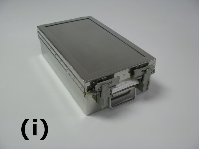
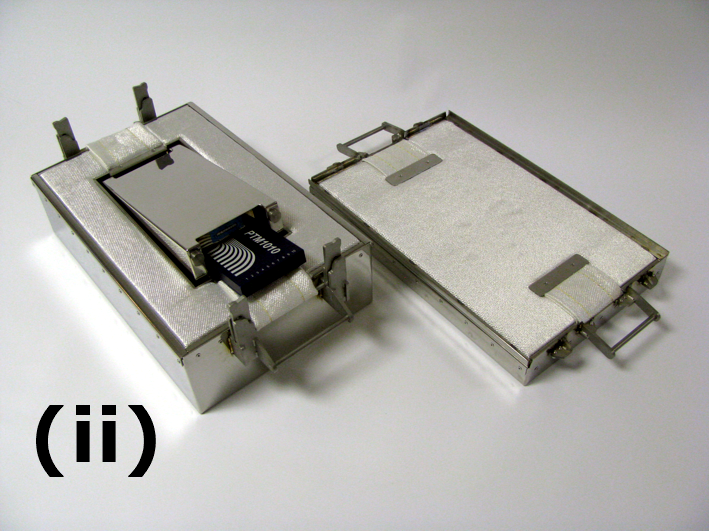
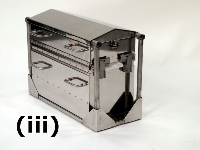
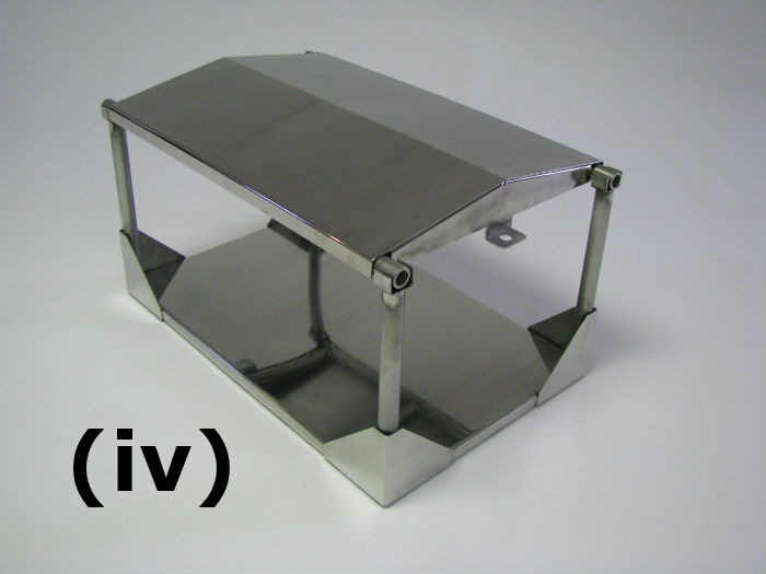
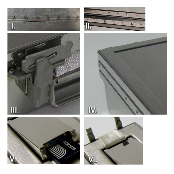
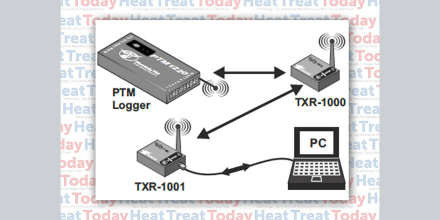
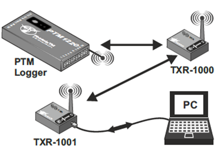
Applying the “Thru-Process” approach to TUS, the measurement system is transferred into the furnace with the survey frame allowing the setup process to be done quickly, safely, and repeatable. (See Figure 2)

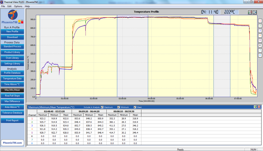
Operating the system with RF telemetry, TUS data is transferred directly from the furnace back to the monitoring PC where at each survey level temperature stabilization and temperature overshoot can be monitored live with TC and logger correction factors applied. The Thermal View Software is developed to ensure that the final TUS report complies fully to the AMS2750E/CQI-9 standards.

Features incorporated into the Thermal View Software to provide full TUS capability include the following:
TUS Level Library – Set-up TUS level templates for quick efficient survey level specification (Survey Temp °F, Tolerance °F, Stabilization, and Survey Times)
TUS Frames Library – Show clearly exact TUS frame construction and probe location using Frame Library Templates – Frame Center and 8 Vertices.
Logger Correction File – Create a logger correction file to compensate TUS readings automatically from the logger’s internal calibration file.
Thermocouple Correction File – Create the thermocouple correction file and use to compensate TUS readings directly.
TUS Result Table & Graph View – For each TUS temperature level, see from the graph or TUS table instantaneously full survey results.
Furnace Class Reporting – Report the specified furnace class at each temperature level.
Overview
The PhoenixTM Temperature Profiling System provides a versatile solution for both performing product temperature profiling and furnace TUS in industrial heat treatment. It is designed specifically for the technical challenges of low-pressure carburizing (LPC) whether implementing either high-pressure gas quench or oil quench methodology, providing the means to Understand, Control, Optimize and Certify the LPC Furnace and guarantee product quality and process operation efficiency and certification.