Two entities located in Meadville, PA will now operate as one organization.
SECO/WARWICKand SECO/VACUUM Technologies have consolidated their U.S. operations. Piotr Zawistowski, the current president of SECO/VACUUM, will remain at the helm of the merged organization.
Growing market needs, changing geopolitical conditions, and the aim to further strengthen the global SECO/WARWICK brand were motivations for the decision.
Sławomir Woźniak CEO SECO/WARWICK Group
Sławomir Woźniak, CEO of the SECO/WARWICK Group shared that “operating under one brand (SECO/WARWICK) is an important step in implementing our product strategy in the North American market. The consolidation will strengthen brand recognition, optimize operational processes, and simplify administrative formalities. I want to emphasize that while the formal structure and name change, the values, mission, and vision of the SECO/WARWICK Group remain unchanged. The goal of the entire undertaking is growth on all fronts.”
“I would also like to emphasize that all existing product lines of both entities will continue,” added Piotr Zawistowski, Managing Director of the American SECO/WARWICK branch.
Piotr Zawistowski Managing Director SECO/VACUUM
One of the short-term goals following the merger will be the transfer of technology and the expansion of the product portfolio in the American market. The remaining branch of the Group in the USA – RETECH in Buffalo, New York – will maintain its existing production, product segment, and separate brand.
Merger Announcement On SECO/VACUUM Website Source: SECO/VACUUM
Press release is available in its original form here.
A new thermal processing company has launched under the oversight of industry leaders.
High Vacuum Technologies (HVT) has announced its inauguration as a new vacuum furnace manufacturer. HVT is committed to serving the industry with energy efficient equipment.
HVT Logo
The executive team for HVT consists of Suresh Jhawar, named chief executive officer, who has 54 years of experience in the industry. He spent the first ten years of his career at IPSEN USA, holding positions of senior project engineer, manager engineering services, manager marketing services, and technical director of Heavy Equipment Division. Later, he assumed the role of vice president general manager at ABAR Corporation. In 1987 he joined G-M ENTERPRISES as a minority partner and became the sole owner in 2005 and oversaw its acquisition by NITREX of Canada. Jhawar earned BSc in physics, BSME in heat transfer & thermodynamics and a MBA in marketing.
Steve Turmala is one of the co-founders and will serve as HVT’s executive vice president of technology. He has thirty-five years of experience in the furnace industry, working with electrical and computer control systems. He actively seeks out and invents furnace control systems, with particular attention to reliability and early warning signs for malfunctions.
Jeffrey Taino is a co-founder and will serve as the executive vice president of engineering & R&D for HVT. He has over 30 years of industry experience, including design and equipment development for heat processing of zirconia tubes for nuclear energy.
Veena Jhawar will fill the role of chief operating officer and co-founder of HVT. She spent 25 years in her career at G-M Enterprises managing supply chain and operations. Veena has a master of science degree in economics. She is aware of the challenges of increasing costs for materials and the impact of tariffs on the industry, but she is ready to meet those challenges.
In this Technical Tuesday installment, Kazunori Hokaku, business director/general manager/sales engineering dept. at Tokai Konetsu Kogyo shares the sustainability benefits of SiC heating elements.
This informative piece was first released inHeat Treat Today’sMay 2025 Sustainable Heat Treat Technologies print edition.
In recent years, Silicon Carbide (SiC) heating elements have been increasingly used in demanding applications involving high temperatures and extreme atmospheres. Battery material manufacturing is one of many such applications. Therefore, improved service life contributes to increased productivity and sustainability as well as reduced industrial waste. This article discusses the long service life for recrystallized SiC heating elements having both excellent oxidation and corrosion resistance.
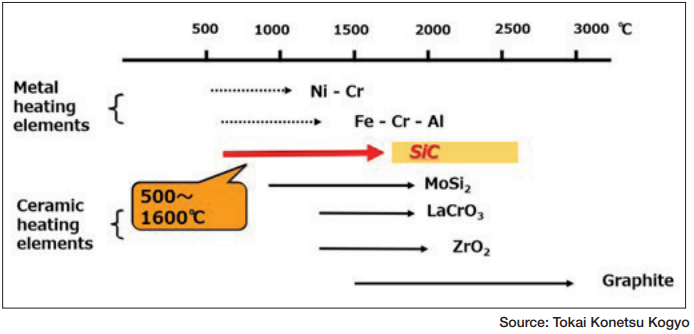
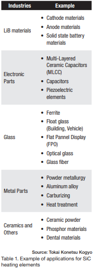
Tokai Konetsu Kogyo in Japan has been manufacturing EREMA® SiC heating elements since 1936. SiC heating elements are categorized as ceramic heating elements, which are widely used in a temperature range between 932°F–2912°F (500°C–1600°C) as shown in Figure 1.
Figure 1. Temperature range for heatingTable 1. Example of applications for SiC
heating elements
The heat value per unit area (i.e., watt density) of SiC heating elements is quite high, 5 to 10 times that of metallic Nichrome wire heating elements, for example. SiC heating elements are chemically stable and an environmentally friendly source, free of air and noise pollution compared to gas-fired or liquid fuel systems. As such, they are chosen and used for a variety of applications, such as Lithium-ion battery material (i.e., cathode/anode/solid state battery materials), powder metallurgy, aluminum, hardening and case hardening applications (e.g., carburizing), electronic parts (MLCC, ferrite), and dental materials as shown in Table 1.
SiC heating elements come in a variety of shapes, namely straight rod, U-shaped, and W-shaped designs. They are affordable and easy to handle compared to other ceramic heating elements. It is important to remember, however, that their service life is drastically influenced by high temperatures and the atmosphere.
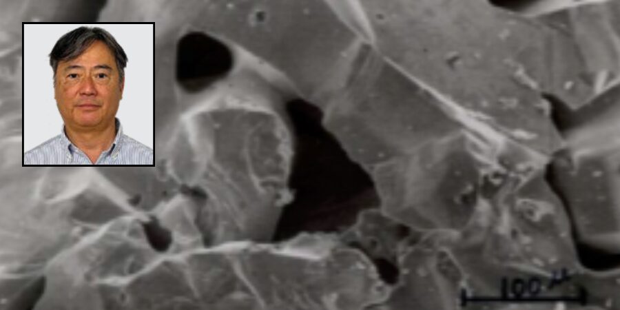
The failure mechanism of a SiC heating element to its service life is shown in Figure 2. SiC reacts with O2 and creates SiO2, by which the resistance of the heating element increases.
Therefore, increasing bulk density and reducing specific surface area are key to service life longevity. This relationship between bulk density and service life in alkaline atmosphere (Li2CO3) has been explored by Tokai Konetsu Kogyo using scanning electron microscopy (SEM) photos with results as shown in Figure 3.
Figure 2. Mechanism of resistance increase (service life)
Silicon Carbide 101
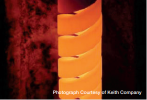
■ Electric heating elements are a popular choice of many heat treaters. They come in a variety of shapes, sizes, and materials. One of the most common types are silicon carbide (SiC) heating elements, known by several tradenames including Globar™ and StarBar™. They are used extensively throughout the heat treating industry when high temperatures, maximum power, and heavy duty cycles are required.
A SiC heating element is typically, but not always, an extruded tubular rod or cylinder made from high purity grains of silicon carbide that are fused together by either a reaction bonding process or a recrystallization process at temperatures in excess of 3900°F (2150°C). The result is a chemically stable material with a low thermal expansion coefficient and little tendency to deform.
Spiral-cut silicon carbide heating element design provides increased resistance for applications up to 3000°F (1650°C)
Recrystallization forms fine grains of silicon carbide that act as “bridges” or connection points between larger grains thus forming conductive pathways. The number of bridges formed dictates the material’s resistance: the greater the number, the lower the resistance. The secret to the creation of a good heating element is controlling this formation process within the material to develop a consistent electrical resistance
The factors that influence the life of a SiC heating element include the type of furnace atmosphere, watt density, operating temperature, type of service (continuous or intermittent), and maintenance. Furnace type, design, and loading play an important role as well. SiC heating elements are extremely versatile operating, for example, in air up to 3000°F (1650°C).
Finally, the choice of heating element depends on many factors. For example, SiC heating elements are capable of higher operating temperatures and higher watt loadings than say metallic elements; they are self-supporting and can be used in furnaces either too wide or too long to be spanned by other element types and are relatively easy to change while hot. SiC heating elements are used extensively in brazing and sintering furnaces running continuously at or above 2050°F (1120°C) and for other processes where the temperature range lies between 2375°F (1300°C) and 2725°F (1500°C).
With permission from the author, Dan Herring, the information cited has been used in part from, Herring, Daniel H. “Electric Heating Elements Part One: Silicon Carbide.” Industrial Heating, September 2008. ■
SEM photos show the Sustainable Development Goals (SDGs) model observed increased bulk density with low porosity and very thick neck growth of SiC grains. The specific surface area for the SDGs model of 0.03 m2/g by Brunauer–Emmett–Teller (BET) method is smaller than that of the standard high-density grade of 0.05 m2/g.
Figure 3. Life test (resistance increase in alkaline atmosphere)
As a result, the graph in Figure 3 shows that the service life for the EREMA®SDGs model (BD = 2.65) is the longest, which means a reduction not only in downtime of furnace operation but also of industrial waste.
About The Author:
Kazunori Hokaku Business Director/General Manager/Sales Engineering Dept Tokai Konetsu Kogyo
Kazunori Hokaku graduated from Kyoto Institute of Technology in 1985 with a major in ceramics. He has been with Tokai Konetsu Kogyo Co., Ltd., since 1985 and is currently the business director/general manager/sales engineering dept.
Heat Treat Today publishes twelve print magazines annually and included in each is a letter from the publisher, Doug Glenn. This letter is from theMay 2025 Sustainable Heat Treat Technologiesprint edition.
This month’s magazine focuses on green and sustainable technologies. I love this topic, and I’ve been thinking about what motivates us to care for the planet.
Our presuppositions about the environment significantly affect the thoughts we have and actions we take. The presuppositional glasses we wear affect the way we see the world. If we have proverbial rose-tinted glasses, the world always looks “rosy.” And if the world looks rosy, we won’t do much to fix it.
In this column, I’m suggesting that “stewardship” has different and better presuppositions than “sustainability.” I don’t expect everyone to wear the same presuppositional glasses, but I hope the following discussion will stimulate thought.
Stewardship vs. Sustainability
Stewardship, as mentioned above, has a variety of premises. It is a distinctively Judeo-Christian concept derived largely from Genesis 1:28 in the Bible, which states that God said, “Be fruitful and multiply, and fill the earth, and subdue it; and rule over the fish of the sea and over the birds of the sky and over every living thing that moves on the earth.” The “subdue it” part of this verse is also referred to as the “Dominion Mandate.” After making the world, God explicitly assigns mankind as stewards of what He made and commands them to take care of it.
If this is true, then our thinking about climate change, sustainability, and our environmental responsibilities will change.
Here are some examples.
Ownership of Earth
Stewardship changes the idea of how we think about ownership. Who really owns the planet? Sustainability says that 1) mankind owns it, 2) no one owns it, or 3) animals own it. In all cases, mankind is not responsible to anyone higher than himself for how he treats the planet.
Stewardship, on the other hand, puts a whole new spin on how man interacts with the planet. If God made the earth and gave man responsibility to care for it, then man is accountable to Him for how we care for it. The compelling driver behind caring for the environment is significantly different and eternal with stewardship mentality. Answering to ourselves, our children, the earth itself, or the animals for the way we care for the earth is less motivational than answering directly to God.
Eternality of Earth
The stewardship mentality also changes the timeline. Sustainability assumes that the planet will go on forever in varying conditions of well-being depending on our care — it has a never-ending timeline. The stewardship mentality has a fixed end date. More importantly, that end date has accountability associated with it. One day, the world will cease to exist as we know it and God will hold mankind responsible, both individually and corporately, for how well we’ve handled it.
Man Is the Problem
One final presupposition that changes if we switch from a sustainability to stewardship mindset is our view of man. Sustainability often comes with the assumption that man is the problem — a scourge on the earth. Most of us have heard the concept that the world would be a better place if it weren’t for man mucking it up. Stewardship is the opposite. It claims that the earth has been given to man to rule over it, subdue it, and care for it. Man, instead of being the scourge of the earth, becomes the most important and most valuable creature.
Conclusion
There are a lot of reasons why people love and care for the environment. Lord willing, stewardship will play a bigger role in the future. In the meantime, please enjoy the technical content in this month’s stewardship, I mean, sustainability edition.
In today’s editor’s page, Heat TreatToday‘s Daily Editor, Tiffany Ward, provides a history of U.S. Steel and the recent Nippon Steel merger.
What is U.S. Steel’s history and what does the future look like for this company after a new merger? This short, informative post fills in the gap.
U.S. Steel Yesterday
If you walk along a Pittsburgh street, the phrase “Steel City” will likely appear on a wall mural or passerby’s hoodie. In 1901 four men (J.P. Morgan, Charles Schwab, Andrew Carnegie, and Elbert H. Gary), formed the United States Steel Corporation (known simply as U.S. Steel). Its global headquarters are still located in Pittsburgh, Pennsylvania, where it has a huge local impact.
From its inception, U.S. Steel has made an impact across the country in producing steel for famous structures such as the San Francisco-Oakland Bay Bridge, the United Nations Building in New York City, the “Three Sisters” Bridges in Pittsburgh, the Chesapeake Bay Bridge, and many others. During the Great Depression, the company suffered an all-time low in sales, but recovered, and by 2003 became the fifth largest steel producer in the world.
“Three Sisters” Bridges in Pittsburgh. Source: Bridges and Tunnels
U.S. Steel Today
Almost twenty years later, in 2022, U.S. Steel produced less steel than it had in its founding year, over a century earlier. This was the culmination of a long-standing decline in steel production in the United States, which affected many U.S. producers. On December 18, 2023, Nippon Steel Corporation, a Japanese company, made a $14.9 billion acquisition offer for U.S. Steel and the two companies entered into an official merger conversation. The potential merger agreement between Nippon and U.S. Steel included Nippon’s pledge to invest $2.7 billion to modernize U.S. Steel’s facilities in Pennsylvania and Indiana, and to keep U.S. Steel’s headquarters in Pittsburgh, making the agreement a locally invested issue.
The merger was met with political and economic controversy, facing direct executive orders and review interventions. Both former President Joe Biden, and current President Donald Trump made efforts to block the deal. On January 3, 2025, former President Joe Biden prohibited the acquisition through executive order, reserving executive powers to issue further orders on this matter if needed. According to a statement from The White House, the motivation for such a move was “a strong domestically owned and operated steel industry represents an essential national security priority and is critical for resilient supply chains.” The Biden administration delayed, however, in enforcing that initial order. On April 7, 2025, President Donald Trump made use of those previously reserved powers to direct the Committee on Foreign Investment in the United States to review the acquisition deal to see if further action may be appropriate. President Trump’s rationale mirrored that of former President Biden. He stated to reporters on April 13, 2025, “I don’t think a foreign company should control U.S. Steel.”
Despite this opposition, U.S. Steel affirmed in a press release on April 17 that the two companies were still in a “definite merger agreement,” and referred to the deal as a “pending transaction.”
In a recent development, President Donald Trump changed his tone of opposition to the deal. On May 23, the President made a social media post in support of the merger, which was met with deep appreciation by U.S. Steel in a corresponding press release.
U.S. Steel Tomorrow
U.S. Steel’s Website Logo Source: U.S. Steel Corporation
On June 13, 2025 President Donald Trump signed an executive order permitting the deal to commence, contingent upon an agreement with the Treasury Department to address national security concerns. With White House support being the most significant component to the merger’s conclusion, spirits have now buoyed around its development.
The impending deal brings with it a multi-billion dollar infusion into U.S. Steel’s infrastructure. Nippon now plans to invest $4 billion in a U.S. based steel mill, with the intention of investing $11 billion in total infrastructure projects by 2028.
The prospect of revitalized steel production in the United States brings excitement to many in the heat treatment industry.
This article is being updated to include the most recent developments. Last updated on 06-17-2025.
“About Us – History,” United States Steel Corporation, Accessed April 22, 2025. https://www.ussteel.com/about-us/history.
Biden, Jr., Joseph R. “Order Regarding the Proposed Acquisition of United States Steel Corporation by Nippon Steel Corporation,” White House Archives. January 3, 2025. https://bidenwhitehouse.archives.gov/briefing-room/presidential-actions/2025/01/03/order-regarding-the-proposed-acquisition-of-united-states-steel-corporation-by-nippon-steel-corporation/
Biden, Jr., Joseph R. “Statement from President Joe Biden,” White House Archives. January 3, 2025. https://bidenwhitehouse.archives.gov/briefing-room/statements-releases/2025/01/03/statement-from-president-joe-biden-13/.
Boselovic, L. “Steel Standing: U.S. Steel Celebrates 100 Years,” Pittsburgh Post-Gazette. 2001. https://web.archive.org/web/20181012210047/http://old.post-gazette.com/businessnews/20010225ussteel2.asp
“Cleveland-Cliffs Proposes to Acquire U.S. Steel,” Cliffs. Cleveland Cliffs, August 13, 2023. https://www.clevelandcliffs.com/news/news-releases/detail/600/cleveland-cliffs-proposes-to-acquire-u-s-steel.
“Nippon Steel to invest $4 billion for new U.S. Steel mill,” Reuters, Accessed May 28, 2025. https://www.cnbc.com/2025/05/20/nippon-steel-to-invest-4-billion-for-new-us-steel-mill-reuters-.html
Trump, Donald J. “Review of Proposed United States Steel Corporation Acquisition,” The White House. April 7, 2025. https://www.whitehouse.gov/presidential-actions/2025/04/review-of-proposed-united-states-steel-corporation-acquisition/.
Trump, Donald J. “Regarding the Proposed Acquisition of United States Steel Corporation by Nippon Steel Corporation,” The White House. June 13, 2025. https://www.whitehouse.gov/presidential-actions/2025/06/regarding-the-proposed-acquisition-of-the-united-states-steel-corporation-by-nippon-steel-corporation/
“Trump Opposes Foreign Control of US Steel amid Nippon Steel’s $14 Billion Bid,” The Economic Times, April 14, 2025. https://economictimes.indiatimes.com/news/international/world-news/trump-opposes-foreign-control-of-us-steel-amid-nippon-steels-14-billion-bid/articleshow/120267416.cms.
“United States Steel Corporation,” Accessed April 22, 2025. https://www.ussteel.com.
“United States Steel Corporation to Release First Quarter 2025 Financial Results on May 1, 2025,” United States Steel Corporation, April 17, 2025. https://www.ussteel.com/newsroom/-/blogs/united-states-steel-corporation-to-release-first-quarter-2025-financial-results-on-may-1-2025
“U. S. Steel Statement on President Trump’s Leadership,” United States Steel Corporation, May 28, 2025. https://www.ussteel.com/newsroom/-/blogs/u-s-steel-statement-on-president-trump-s-leadership
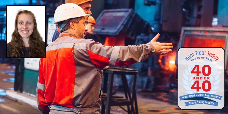
Heat Treat Todaypublishes twelve print magazines a year and included in each is a letter from the editor. This letter is from the May 2025 Sustainable Heat Treat Technologiesprint edition, and serves as the final message from Jayna McGowan, a dear member of the Heat Treat Today team.
Jayna McGowan 40 Under 40 Coordinator Heat Treat Today
Recognizing a job well done, an individual striving for excellence in their work, and someone who demonstrates leadership potential for years to come is not only a form of integrity in the workplace, but an opportunity to encourage a company and an industry to be the best it can be. A work environment that does not recognize excellence risks undermining it, leaving employees demoralized as they tackle the daily challenges inherent to their work. Those who have worked in both environments — the one that pursues and recognizes excellence and the one that does not — know the value of the former. The individual and the company both benefit from recognizing excellence.
This is why it has been an absolute privilege to coordinate Heat Treat Today’s40 Under 40 initiative. Getting to learn about the accomplishments of rising stars in the heat treat industry and then to share those with our readers speaks to the overall integrity of the people and companies in the industry. My favorite part about communicating with individuals who have been nominated is their tendency to be surprised by their nomination — in their minds, they are simply doing their job the way they know how to do it, which makes it all the more encouraging to hear that someone noticed their effort and wants them to be honored for it.
Another aspect I have enjoyed about supervising 40 Under 40 is seeing how the individuals recognized are contributing to the heat treat industry as a whole. Here at Heat Treat Today, we see firsthand how individuals honored in past years are willing to share their experiences and expertise by authoring articles or being interviewed for a Heat Treat Radio episode. Several highlights of these alumni contributions from the past year include:
“3D Printed Coils Outperform Traditional Coils” in our 2025 April print issue, featuring Josh Tucker from Tucker Induction Systems, 40 Under 40Class of 2024
“CQI-9 vs. AMS2759 for Quench Oil Management” in our 2025 March print issue, featuring Michelle Bennett from Idemitsu Lubricants America, 40 Under 40Class of 2023
“Transformative Takeaways” in our 2025 January print issue, featuring Casey O’Neill from RoMan Manufacturing, Inc., 40 Under 40Class of 2022
The example set by these individuals and so many others has the potential to inspire and inform the entire heat treat industry.
Finally, how can you 1) model the integrity of recognizing a job well done in the industry and 2) encourage young leaders like these to continue pursuing excellence? One way is to nominate a North American heat treater you know for the 40 Under 40 Class of 2025. Nominations officially open May 19 and close June 27.
While I will be stepping away from coordinating this initiative to raise my twin girls due in a couple months (future heat treaters?), please reach out to incoming coordinator, Kelsha Wells (kelsha@heattreatoday.com), with any questions about the nomination process.
In heat treating, the choice of power supply is a critical decision. Whether you’re using an AC transformer or a rectified DC system (AC transformer rectifier), this decision plays a significant role in process efficiency, equipment longevity, and operational costs. While AC transformers have been the industry standard for decades, rectified DC power is becoming more relevant due to its distinct electrical and thermal characteristics. Understanding the differences between these two power sources helps in-house heat treaters optimize furnace performance based on their specific application needs.
This informative piece was first released inHeat Treat Today’sMay 2025 Sustainable Heat Treat Technologies print edition.
Electrical Differences: AC vs. Rectified DC Power
AC Transformer Systems
In a traditional setup, an AC transformer steps down high-voltage grid power to the appropriate level for the heating elements. These elements operate on an alternating current waveform, where voltage and current fluctuate between positive and negative cycles at a standard frequency (typically 50 or 60 Hz).
Rectified DC Systems
In a rectified DC system setup, an AC transformer is combined with a rectifier to convert the stepped-down AC voltage into a pulsating or smoothed DC supply. This provides a continuous electrical current rather than an alternating waveform, changing how heat is delivered to the furnace.
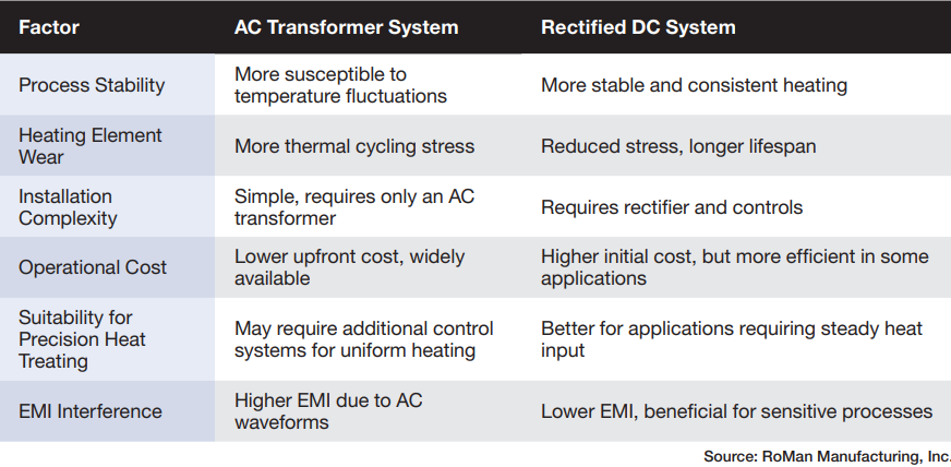
Table 1. Benefits of AC vs. rectified DC power
Heat Distribution and Process Stability
One of the key differences between AC and rectified DC power in furnace heating is how each affects heat distribution within heating elements.
AC Heating
The alternating nature of AC power means the voltage crosses zero multiple times per second, leading to cyclic fluctuations in power delivery. In heat treating, this can create small but notable variations in temperature stability, especially in high-precision applications where uniform heating is critical.
Rectified DC Heating
Because DC power provides a continuous voltage and current, it eliminates these fluctuations. This results in more stable and consistent heating, which can be beneficial in processes that require tight thermal tolerances, such as carburizing, nitriding, and annealing.
Heating Element Performance and Longevity
The type of power supply can also impact the lifespan and efficiency of heating elements.
AC-Powered Heating Elements
Alternating current can cause thermal cycling effects within the heating elements, leading to mechanical stress over time. This may contribute to faster wear, increased oxidation, and potential premature failure of heating elements in some applications. However, for many general heat treating processes, AC remains a cost-effective and widely accepted solution.
Rectified DC-Powered Heating Elements
The stable power flow of rectified DC reduces thermal cycling stress on heating elements, allowing for longer operating life and more efficient heat transfer. This is particularly relevant for graphite and silicon carbide heating elements, which perform better with steady-state power input.
Power System Efficiency and Infrastructure Considerations
When integrating AC vs. rectified DC systems into a heat treating operation, several infrastructure and efficiency factors come into play.
AC Transformer Systems:
Standard in industrial settings and require minimal modification to existing electrical infrastructure
Simpler and often lower cost installation compared to rectified DC systems
More efficient for long-distance power transmission, which can be a factor in large industrial operations with multiple furnaces
Rectified DC Systems:
Require a rectifier in addition to the transformer, adding to equipment costs and complexity
Potentially higher efficiency in localized heating applications by reducing resistive losses in certain furnace designs
Reduced electromagnetic interference (EMI) compared to AC, which can be beneficial in sensitive heat treating processes
Process Suitability: When to Use AC vs. Rectified DC Power
Temperature stability, heating uniformity, and process sensitivity are important factors to consider when choosing between AC and rectified DC power for different heat treatment processes.
Conclusion
Both AC and rectified DC power play important roles in heat treating, and the choice depends on process requirements, equipment lifespan, and infrastructure considerations. AC transformer-powered systems remain the standard due to their low cost, compatibility with existing grids, and simpler installation. They are ideal for general heat treating applications that do not require extreme precision in thermal control. However, rectified DC systems offer more stable heating, reducing wear on heating elements and improving temperature uniformity. While they require additional equipment, they can be beneficial in high-precision applications or when maximizing furnace efficiency is a priority.
Understanding the strengths and limitations of both AC and rectified DC power sources enables heat treaters to select the optimal system for their specific production needs, balancing cost, efficiency, and process performance.
About The Author:
Brian Turner Sales Applications Engineer RoMan Manufacturing, Inc.
For more information: Contact Brian Turner at bturner@romanmfg.com.
The increasing adoption of large-scale aluminum die casting, often termed Giga casting, in the automotive industry presents significant challenges in the manufacturing and maintenance of the massive dies required. Learn how heat treatment plays a critical role in ensuring the performance and lifespan of these Giga dies, primarily made from H13 tool steel or its derivatives.
This informative piece was first released inHeat Treat Today’sMay 2025 Sustainable Heat Treat Technologies print edition.
Introduction
In an article from 2005 on vacuum heat treating of large dies, I concluded, “The use of very large die cast tooling in the automotive industry with part weight over 3 metric tons will increase as aluminum cast parts are increasingly used to lower the manufacturing cost to produce lighter weight automobiles” (Wingens, “H13 Dies.”). Now, 20 years later, a couple hundred “Mega” dies have been heat treated. Six years ago, Tesla decided to take on Giga casting, gaining global attention and taking aluminum die casting to its next level.
Tesla is working on an upgrade to its Giga casting technology to die cast almost all vehicle underbody parts in one piece. They pioneered the use of presses with 6,000 to9,000 tons of clamping pressure to mold the front and rear structures of Model Y during the Giga casting process.
For Tesla, the use of a single component in the rear of the Model Y allowed it to cut related costs by 40%. In the Model 3, Tesla was able to remove 600 robots from assembly by using a single piece from the front and rear of the vehicle (Greco, “Weekly Gigacasting News.”).
Figure 1. Part reduction between Model 3 and Model Y Source: Tesla Q1 2020 Report
They have 14 Giga presses already installed, including two presses with 9,000 tons of clamping pressure for Tesla’s large Cybertruck production at its plant in Austin, Texas, with more to come.
Tesla strategically incorporates inserts in the dies for high-heat zones. These metal elements are specifically placed in areas prone to higher corrosion. Inserts serve a crucial purpose, as they can be replaced individually, mitigating the need to discard an entire costly tool. The dies last hundreds of thousands of shots while individual inserts may only have a lifespan ranging between 30,000 and 80,000 shots (Greco, “Weekly Gigacasting News.”).
Tesla currently employs two sets of dies per machine. While one set is actively mounted on the Giga Press, the other set undergoes routine maintenance. These sets are periodically rotated to ensure continuous and efficient production (Greco, “Weekly Gigacasting News.”).
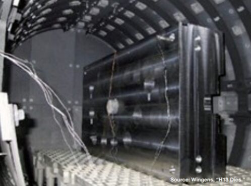
Figure 2. Tesla Model Y single aluminum die-cast piece Source: Wingens, “H13 Dies”
Ford, Toyota, Volkswagen, Volvo, and most Chinese electric car manufacturers have Giga Presses on order. The first North American Giga casting machine, aside from Tesla’s, will be installed at Linamar in Ontario (Greco, “Weekly Gigacasting News.”). This highlights the transformation occurring within the automotive industry with the increasing demand for lighter vehicles and reduced manufacturing costs, which in turn is driving the adoption of large aluminum structural castings produced through Giga casting (Greco, “Weekly Gigacasting News.”). This revolutionary technique necessitates the use of exceptionally large die-casting dies, often weighing several metric tons.
These Giga dies, typically manufactured from hot-work tool steels, such as H13, are subjected to extreme thermal and mechanical stresses during the high-pressure injection of molten aluminum. Consequently, heat treatment plays a pivotal role in achieving the desired mechanical properties, maximizing die life and minimizing the risks of distortion and cracking. This article delves into the complexities of heat treating Giga dies, highlighting the evolution of techniques, current challenges, and emerging solutions.
Historical Perspective
Figure 3. GM Powertrain 16” cube quench test
The heat treatment of large aluminum die-casting dies has evolved significantly over the last few decades. In the early days of vacuum heat treating for die-casting dies (1980s and 1990s), the primary focus was on minimizing distortion and achieving a clean surface finish. This was often accomplished using slow gas quenching rates (<30°F or 17°C/min), which, while reducing distortion, led to the precipitation of grain boundary carbides and consequently, shorter die life due to reduced impact toughness (Wingens, “H13 Dies.”).
Recognizing the need for improved die performance, the North American Die Casting Association (NADCA), along with leading companies in the die casting industry, issued recommendations for a minimum surface quench speed of 50°F/min (28°C/min). This shift, coupled with the selection of higher quality die materials and the development of heat treatment specifications, such as GM Powertrain DC-9999-1 (1995) and Ford AMTD DC2010 (1999), resulted in significant cost savings and improved die life within the North American automotive industry. These specifications emphasized the importance of both material quality and heat treatment procedures (Wingens und Edenhofer, “Bauweise und Funktion.”).
Challenges in Heat Treating Giga Dies
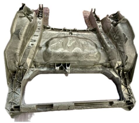
Figure 4. H13 aluminum die casting mold of 5.6 metric tons
Heat treating large H13 aluminum die-casting dies has traditionally balanced the need for sufficient quench rates to achieve robust mechanical properties against the risk of distortion and cracking. As modern automotive and industrial applications demand ever-larger die-cast components, metallurgists and equipment suppliers have focused on several key developments: faster quenching methods in high-pressure vacuum furnaces; process strategies, such as interrupted quenching, to stabilize temperature gradients; and increasingly powerful auxiliary systems capable of handling extremely heavy loads and high thermal loads (Wingens, “H13 Dies.”).
Achieving Adequate Quench Rates to Avoid Grain Boundary Precipitation
H13 (or similar hot-work tool steels) benefits from a sufficiently rapid quench to bypass detrimental grain boundary precipitation, which compromises toughness and die longevity. Many die-casting specifications — including those from NADCA — recommend a minimum quench speed of 50°F/min (28°C/min) measured near the die surface to maintain a uniformly fine microstructure (Wingens, “H13 Dies.”). Without such fast cooling, large dies can exhibit unwanted carbides at prior austenite grain boundaries and reduced impact strength.
For dies weighing several metric tons, however, achieving even 50°F/min (28°C/min) at the die surface is nontrivial. Heat must be extracted swiftly from thick cross-sections, yet the bulk thermal conductivity of H13 places inherent limits on how quickly the die core can be cooled. The result has been widespread adoption of high-pressure gas quenching (HPGQ) in single- or multi-chamber vacuum furnaces, with nitrogen pressures often exceeding 10 or 15 bar (Wingens, Maximizing Quenching and Cooling in Vacuum Heat Treating 2015).
The advent of Giga casting, with its significantly larger dies (weighing > 3 metric tons), introduces a new set of challenges for heat treatment processes. Achieving the required metallurgical properties and minimizing defects in such massive components demands sophisticated techniques and equipment.
Figure 5. Acceptable (left) and unacceptable (right) H11 microstructure (500x)
Key challenges include:
Uniform heating and cooling: Ensuring uniform temperature distribution throughout the large die volume during heating to the austenitizing temperature and subsequent quenching is critical to avoid uneven phase transformations and the development of internal stresses that can lead to distortion or cracking.
Achieving adequate quench rates: Extracting heat swiftly from the thick cross-sections of Giga dies to achieve the recommended quench rate of at least 50°F/min (28°C/min) at the surface thermocouple (Ts), as mandated by NADCA #207, is nontrivial due to the inherent limitations of the thermal conductivity of H13 steel.
Minimizing distortion and cracking: The substantial temperature difference between the surface and the core during rapid quenching increases the risk of both distortion and cracking in these large components.
Applying existing specifications: Current specifications, like NADCA #207, were primarily designed for die inserts estimated at up to 1 ton. The applicability and adequacy of these specifications for Giga dies, which weigh several tons, are being questioned. Issues, such as the number and location of test coupons needed to accurately represent the properties of the entire block, need to be addressed.
Equipment capacity: Heat treating Giga dies necessitates vacuum furnaces with adequate weight and cooling capacity, capable of handling the large dimensions and masses involved.
Modern Heat Treatment Techniques for Giga Dies
Advanced vacuum heat treatment technologies and process strategies have been developed and implemented to address the challenges associated with heat treating Giga dies.
High-Pressure Gas Quenching (HPGQ)
The widespread adoption of HPGQ in single- or multi-chamber vacuum furnaces, with nitrogen pressures often exceeding 10 or 15 bar, is crucial for achieving the necessary rapid cooling rates for large H13 dies. Systems with radial gas nozzle systems and powerful fans (up to 800 kW) ensure effective gas flow through the large load volume (Wingens, “Maximizing.”).
Directional Cooling
Some advanced vacuum furnaces incorporate directional controlled cooling capabilities, allowing for the manipulation of gas flow patterns to promote more uniform heat extraction from complex die geometries, thus minimizing distortion (Wingens, “Maximizing.”).
Interrupted Quenching (Isothermal Hold)
Interrupted quenching techniques are employed to mitigate the risk of distortion and cracking caused by extreme temperature gradients. By pausing the quench at an intermediate temperature (sometimes referred to as a “warm bath” effect), the internal heat of the die has time to diff use outwards, equalizing temperatures and reducing residual stresses before the quenching process resumes (Wingens, “Maximizing.”).
Large Vacuum Furnaces
Furnace manufacturers have developed Giga vacuum furnaces specifically designed to handle the size and weight of these large dies, with load capacities up to 5,000 kg or even 8 tons (Wingens, “H13 Dies.”).
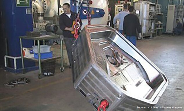
Figure 6. A 6t H13 die, the largest of its time (2004), processed for the German automotive industry
Adherence to NADCA Recommendations
Despite size difference, the fundamental principles of heat treating H13 steel for die casting, as outlined in NADCA #207-2003, remain relevant. Achieving a minimum surface cooling rate of 50°F (28°C) per minute in the critical temperature range is still a key objective. Furnaces with high backfill capabilities (minimum 2 bar for premium, 5 bar for superior quality) are preferred.
Precise Temperature Control
Modern furnaces are equipped with sophisticated digital controls and multiple thermocouples to monitor and adjust temperature profiles in real time, ensuring uniform heating to the austenitizing temperature — typically around 1885°F (1030°C) for H13 — and precise control during the quenching and tempering stages.
Following the rapid quench, a minimum of two tempering cycles is required, with cooling to ambient temperature between each cycle. A final stress temper is often performed to relieve residual stresses.
Impact of Material Science
While the heat treatment process is critical, the selection of high-quality die steel is equally important. Typically, Giga dies are made from premium or superior grade H13 steel, which, according to NADCA #207-2003, should meet stringent requirements for cleanliness, micro-banding, and impact toughness.
Ongoing research also explores the use of improved die steels like Dievar and QRO-90, which exhibit enhanced thermal fatigue resistance. Proper heat treatment is essential to unlock the full potential of these advanced alloys.
Future Trends and Outlook
The field of heat treating Giga dies is continuously evolving to meet the increasing demands of the automotive industry. Future trends and considerations include:
Revision of specifications: The NADCA organization recognizes that the current NADCA #207 specification may need to be revisited to better address the unique challenges posed by Giga dies in terms of testing, quality assurance, and acceptable property variations across the large die volume.
Advanced process control: The increasing use of heat treatment simulation and finite element method (FEM) analysis allows for the prediction and optimization of hardening processes, including the estimation and compensation of thermal gradients.
Innovative heat treatment processes: Emerging techniques like long martempering, which offer a balance of high hardness and toughness in less time, are being explored as potential alternatives to traditional quenching and tempering for hot-work tool steels (Duarte, “Improving Hardening.”).
Energy efficiency: Efforts to reduce the energy consumption associated with HPGQ are ongoing, focusing on optimizing furnace design and control systems.
Integration with Industry 4.0/5.0: Digitalization and automation are expected to drive advancements in heat treatment processes, leading to improved efficiency, higher quality, and simplified task execution.
Figure 8. Loading of 5t H13 into a 15 bar Ipsen SuperTurbo Treater
Conclusion
The efficient and effective heat treatment of Giga dies is paramount to the success of large-scale aluminum die casting in the automotive industry. While the fundamental principles of heat treating H13 steel remain relevant, the sheer size and weight of these dies necessitate the use of advanced vacuum furnace technologies, including HPGQ, directional cooling, and interrupted quenching strategies. Adherence to industry recommendations, such as the minimum quench rates specified by NADCA, is crucial for achieving the desired metallurgical properties and maximizing die lifespan. As the Giga casting market continues to expand, ongoing research and development in heat treatment processes, equipment, and specifications will be essential to meet the evolving demands for these critical manufacturing tools.
References
Chrysler Corporation, Hot Work Tool Steel Manufacturing Standard, Auburn Hills, MI, 1983.
Duarte, Paulo. “Improving Hardening and Introducing Innovation for In-House Heat Treat.” Heat Treat Today, March 2025, https://www.heattreattoday.com/improving-hardening-and-introducing-innovation-for-in-house-heat-treat.
Greco, Luca. “Weekly Gigacasting News.” 2024.
Wingens, Thomas and Bernd Edenhofer. “Bauweise und Funktion eines neuartigen Großkammer-Vakuumofens zum Härten von Schweren Formen und Gesenken.” 60thHeat Treat Colloquium (2005).
Wingens, Thomas. “Maximizing Quenching and Cooling in Vacuum Heat Treating.” 28th ASM Heat Treating Society Conference (2015).
Wingens, Thomas. “Vacuum Furnace Hardening of Very Large H13 Dies.” Industrial Heating, January 2005.
About The Author:
Thomas Wingens Founder & President Wingens Consultants
Thomas Wingens, founder and president of WINGENS CONSULTANTS, boasts over 35 years of experience in the heat treat industry, more than 15 of which are in strategic and executive positions. With his masters in Material Science and Business Administration as well as having served as a heat treater and metallurgist, Thomas holds a unique combination of academic knowledge and industry skills. He has worked in executive positions at Ipsen, Bodycote, SECO/WARWICK, and Tenova. Thomas has also contributed his knowledge and experience as a co-presenter with Doug Glenn at Heat Treat Boot Camp for the last five years.
For more information: Contact Thomas Wingens at wingens@gmail.com.
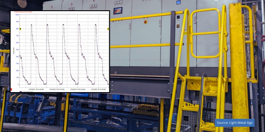
When an extrusion plant in Ohio began to experience production stoppages and higher temperature variability in their 7 inch press line, they sought out an upgrade with a new induction heating furnace. This article highlights the technical components of the new furnace, revealing its upgrade as an important step in ensuring the efficient production and delivery of high quality aluminum extrusions.
An Excerpt:
The furnace replacement project had several clear objectives—significantly improve process reliability, provide accurate temperature uniformity, and ensure high energy efficiency. In addition, the furnace needed to be installed during GEI’s 2024 Christmas shutdown.
Several furnace concepts were investigated during the course of the project. GEI’s preferred method, from a process control perspective, would have been to retain and modify the induction coil of the original furnace and also add a new induction furnace to apply a temperature taper to the billet. In this scenario, the original coil would be used to apply the base temperature, while the new furnace would be responsible for accurately tapering the billet.
Unfortunately, this concept proved to be impractical for several reasons . . .
Click here to read the entire article byLight Metal Age.