Where did the ±0.1°F AMS2750 requirement come from and how should heat treaters approach this specification, an important change that entails major buy-in? Andrew Bassett, president and owner of Aerospace Testing and Pyrometry, was at the AMS2750F meeting. He shares the inside scoop on this topic with Heat Treat Today and what he expects for the future of this standard.
Heat Treat Radio podcast host and Heat Treat Today publisher, Doug Glenn, has written a column on the topic, which you can find here; read it to understand some of the background, questions, and concerns that cloud this issue.
Below, you can watch the video, listen to the podcast by clicking on the audio play button, or read an edited transcript.
The following transcript has been edited for your reading enjoyment.
Doug Glenn: Andrew Bassett, president and owner of Aerospace Testing and Pyrometry, Inc., somewhere in eastern Pennsylvania. We don’t know because you’re on the move! What is your new address, now, by the way?
Contact us with your Reader Feedback
Andrew Bassett: We are in Easton, Pennsylvania at 2020 Dayton Drive.
Doug Glenn: Andrew, we want to talk a bit about this ±0.1°F debate that is going on. It was actually precipitated by the column that I wrote that is in the February issue.
I just wanted to talk about that debate, and I know that you’ve been somewhat involved with it. So, if you don’t mind, could you give our listeners a quick background on what we are talking about, this ±0.1°F debate.
Andrew Bassett: To be honest with you, being part of the AMS2750 sub team, one of the questions came up for us during the Rev F rewrite was this 0.1°F readability — wanting to kind of fix this flaw that’s been in the standard ever since the day that AMS2750 came out. With instrumentation, for instance, you have ±2°F (the equivalent would be 1.1°C). At 1.1°C, the question became, If your instrumentation does not show this 0.1 of a degree readability, how can you show compliance to the standards?
Andrew Bassett President Aerospace Testing and Pyrometry Source: DELTA H
Then, it morphed into other issues that we’ve had in the previous revisions where we talk about precise temperature requirements, like for system accuracy testing: You’re allowed a hard number ±3° per Class 2 furnace or 0.3% of reading, whichever is greater. Now, we have this percentage. With anything over 1000°F, you're going to be able to use the percentage of reading to help bring your test into tolerance. In that example, 1100°F, you’re about 3.3 degrees. If your instrumentation doesn’t show this readability, how are you going to prove compliance?
That’s what it all morphed into. Originally, the first draft that we proposed in AMS2750F was that all instrumentation had to have 0.1°F readability. We got some feedback (I don’t know if I want to say “feedback” or "pitchforks and hammers") that this would be cost-prohibitive; most instrumentation doesn't have that readability, and it would be really costly to go out and try to do this. We understood that. But, at the end of the day, we said: The recording device is your permanent record, and so that’s what we’re going to lean on. But we still had a lot of pushback.
We ended up putting a poll out to AMEC and the heat treating industry to see what their opinions were. We said that with the 0.1 readability (when it came to a percentage reading), recording devices would read hard tolerances. So, for instance, an SAT read at 3° would be just that, not "or .3% of reading."
There was a third option that we had put out to the community at large, and it came back as the 0.1° readability for digital recorders, so that’s where we ran with the 0.1° readability.
When it was that big of an issue, we didn’t make the decisions ourselves; we wanted to put it out to the rest of the community. My guess is not everyone really thought the whole thing through yet. Now people are like, ok, well now I need to get this 0.1° readability.
Again, during the meetings, we heard the issues. Is 0.1° going to really make a difference to metal? If you have a load thermocouple that goes in your furnace and it reads 0.1° over the tolerance, does it fail the load? Well, no, metallurgically, we all know that’s not going to happen, but there’s got to be a line in the sand somewhere, so it was drawn at that.
"...that hard line in the sand had to be drawn somewhere..." Source: Unsplash.com/Willian Justen de Vasconcellos
That’s a little bit of the background of the 0.1° readability.
Doug Glenn: So, basically, we’re in a situation, now, where people are, in fact (and correct me if I’m wrong here), potentially going to fail SATs or tests on their system because of a 0.1° reading, correct? I mean, it is possible, correct?
Andrew Bassett: Yes. So, when the 0.1° readability came out in Rev F, we gave it a two-year moratorium that with that requirement, you still had two more years. Then, when Rev G came out, exactly two years to the date, we still had a lot of customers coming to us, or a lot of suppliers coming back to us, and saying, “Hey, look, there’s a supply shortage on these types of recorders. We need to buy some time on this.” It ranged from another year to 10 years, and we’re like — whoa, whoa, whoa! You told us, coming down the pike before, maybe you pushed it down the road, whatever, probably Covid put a damper on a lot of people, so we added another year.
So, as of June 30th of 2023, that requirement is going to come into full play now. Like it or not, that’s where the standard sits.
Doug Glenn: So, you’re saying June 30th, 2023?
Andrew Bassett: Yes.
Doug Glenn Alright, that’s good background.
I guess there were several issues that I raised. First off, you’ve already hit on one. I understand the ability to be precise, but in most heat treatment applications, one degree is not going to make a difference, right? So, why do we push for a 0.1° when 1° isn’t even going to make a difference?
Andrew Bassett: We know that, and it’s been discussed that way. But, again, that hard line in the sand had to be drawn somewhere, and that was the direction the community wanted to go with, so we went with that. Yes, we understand that in some metals, 10 degrees is not going to make a difference, but we need to have some sort of line in the sand and that's what was drawn.
Doug Glenn: So, a Class 1. I was thinking the lower number was a tighter furnace. So, a Class 1 (±5), and you’re saying, that’s all the furnace is classified for, right, ±5? So, if you get a reading of 1000°, it could be 1005° or it could be 995°. Then, you’re putting on top of that the whole idea that your temperature reading has got to be down to 0.1°. There just seems to be some disconnect there.
So, that was the first one. You also mentioned the instrumentation. It’s been pointed out to me, by some of the instrumentation people, that their instruments are actually only reading four digits. So up to 99.9 you actually have a point, but if it goes to 1000°, you’re out of digits; you can’t even read that. I mean, they can’t even read that down to a point.
"So, if you get a reading of 1000°, it could be 1005° or it could be 995°." Source: Unsplash.com/Getty Images
Andrew Bassett: Correct. On the recording side of things, we went away from analog instrumentation. The old chart papers, that’s all gone, and we required the digital recorders with that 0.1° readability, as of June 30th of this year.
Again, the first draft was all instrumentation. That would be your controllers, your overtemps, and we know that limitation. But everyone does have to be aware of it. We still allow for this calibration of ±2 or 0.2%. If you’re doing a calibration, let’s say, on a temperature control on a calibration point at 1600° and the instrument only reads whole numbers, you can use the percentage, but you would have to round it inward. Let’s use 1800°, that would be an easier way to do it. So, I’m allowed ±2 or 3.6° if I’m using the percentage of reading, but if the instrument does not read in decimal points for a controller or overtemp, you would have to round that down to ±3°.
Doug Glenn: ±3, right; the 0.6° is out the window.
Andrew Bassett: Correct. I shouldn’t say we like to bury things in footnotes, but this was an afterthought. In one of the footnotes, in one of the tables, it talks about instrumentation calibration that people need to be aware of.
Doug Glenn: Let’s just do this because I think we’ve got a good sense of what the situation is, currently. Would you care to prognosticate about the future? Do you think this is going to stand? Do you think it will be changed? What do you think? I realize you’re speaking for yourself, here.
Andrew Bassett: I’m conflicted on both sides. I want to help the supply base with this issue but I’m also on the standards committee that writes the standard. I think because we’re so far down the road, right now — this requirement has been out there since June 2022 — I don’t see anything being rolled back on it, at this point. I think if we did roll it back, we have to look at it both ways.
If we did roll this back and say alright, let’s just do away with this 0.1° readability issue, we still have to worry about the people processing in Celsius. Remember, we’re pretty much the only country in the world that processes in Fahrenheit. The rest of the world has been, probably, following these lines all along. If we rolled this back, just think about all the people that made that investment and moved forward on the 0.1° readability and they come back and say, “Wait a minute. We just spent a $100,000 on upgrading our systems and now you’re rolling it back, that’s not fair to us.”
At this point, with the ball already rolling, it would be very interesting to see when Nadcap starts publishing out the audit findings when it comes to the pyrometry and this 0.1° readability to see how many suppliers are being hit on this requirement and that would give us a good indication. If there are a lot of yeses on it then, obviously, a lot of suppliers haven’t gone down this road. My guess is, for the most part, anybody that’s Nadcap accredited in heat treating — and this goes across chemical processing, coatings, and a few other commodities — I think has caught up to this.
Personally, I don’t think this is going to go away; it’s not going to disappear. It’s going to keep going down this road. Maybe, if people are still struggling with getting the types of devices that can have that 0.1° readability, then maybe another year extension on it, but I don’t know where that is right now. I haven’t gotten enough feedback from aerospace customers that say, "Hey, I can’t get the recorder." I mean,
Doug Glenn: I just don’t understand, Andrew, how it’s even physically possible that companies can record something as accurately as 0.1° if the assembly or thermocouple wire is rated at ±2°? How is that even possible that you can want somebody to be accurate down to ±0.1° when the thing is only accurate up to ±2°?
Andrew Bassett: Right, I get that. We can even go a lot further with that and start talking about budgets of uncertainty. If you look at any reputable thermocouple manufacturer or instrument calibration reports that are ISO 17025, they have to list out their measurements of uncertainty, and that gives you only the 98% competence you’re going to be within that accuracy statement.
Yes, I get the whole issue of this .1° readability. There were good intentions were to fix a flaw, and it spiraled. We’ve seen where PLCs and some of these high logic controllers now can show the .1° readability, but they automatically round up at .5°. Are you now violating the other requirements of rounding to E29? Now, I think we’ve closed out the poll in the standard, but you’re right. We were trying to do the right thing. Personally, I don’t think we gave it all that much further thought on that except hey, let’s just make recorders this way and this should be okay.
Doug Glenn: Right. No, that’s good. Let me be clear, and I think most everybody that was involved with the standards are excellent people and they’re trying to do the right thing. There is no dissing on anybody that was doing it. I’m not a furnace guy, right, I’m a publisher — but when I look at it, I’m going: okay, you’re asking somebody to be as accurate as 0.1° on equipment that can only do ±2°. That’s a 4° swing and you’re asking them to be within 0.1°, basically.
Andrew, this has been helpful. It’s been good hearing from you because you’re on the frontline here. You’ve got one foot firmly planted in both camps.
Andrew Bassett: I’m doing my best to stay neutral with it all.
Doug Glenn: Anyhow, I appreciate it, Andrew. You’re a gentleman. Thanks for taking some time with us.
Andrew Bassett: Thanks, Doug. Appreciate it.
About the expert: Andrew Bassett has more than 25 years of experience in the field of calibrations, temperature uniformity surveys, system accuracy testing, as well an expertise in pressure, humidity, and vacuum measurement calibration. Prior to founding Aerospace Testing & Pyrometry, Andrew previously held positions as Vice President of Pyrometry Services and Director of Pyrometry Services for a large commercial heat treater and Vice President and Quality Control Manager for a small family owned business.
Heat TreatRadio host Doug Glenn talks with Joe Powell of Integrated Heat Treating Solutions in this third of a four episode series about bringing heat treating into the 21st century. This episode covers the fascinating heat treatment of a fracking pump valve seat.
Below, you can either listen to the podcast by clicking on the audio play button, or you can read an edited version of the transcript.
The following transcript has been edited for your reading enjoyment.
Doug Glenn (DG): We're continuing our conversation with Joe Powell of Integrated Heat Treating Solutions. on rethinking heat treating. I strongly recommend that you listen to parts 1 and 2 of this series as well as today's episode. All three are fascinating. To hear the first two parts, click here.
Today, we’ll be talking about what I think, if you've listened to the first two episodes of this four part series, is a very fascinating, I think, somewhat revolutionary advancement in heat treat.
Today, basically what we want to talk about is a really interesting example of the general concept of what we talked about in session one. I want to review that first session very briefly and ask you a couple of other quick questions before we jump into the example of a fracking pump valve seat, which is where we're headed today. But first, maybe from a 30,000-foot view, Joe, tell us what we're talking about here. If you were to put this in a minute, how would you describe what it is you've been doing over at Integrated Heat Treating Solutions?
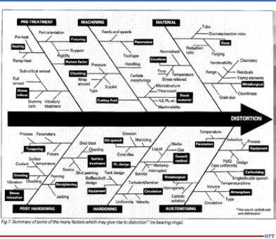
Joe Powell (JP): Integrated Heat Treating Solutions (IHTS) is a consultancy that takes 75 years of practical commercial heat treating and applies it to help part-makers make better parts by using heat treating knowledge. We also work with the material-makers who want to get more added value out of a given hardenability material. What IHTS is essentially doing is taking off from the idea that quenching causes the most problems in heating: it causes distortion, part cracking and size change that is unpredictable. That distortion engineering has been part of the ASM and other societies that have had task forces, committees, and various conferences that are dedicated to the control of distortion.
Potential factors influencing distortion (Source: American Gear Manufacturers Association, sourced by Joe Powell)
The reality is that the control of distortion has been approached by many, many people, including Dr. George Tautin, who was one of the inventors of the reverse solubility polymers when he worked for Dow Chemical and Union Carbide, and Dr. Kovosko in the former Soviet Union, who was my partner in IQ Technologies starting back in 1999. What we've discovered working with all of these very smart people is that the quench cooling rate and its relationship to causing part distortion or part cracking is a bell shape curve. In other words, if you quench very slowly in air or gas or hot oil or martemper salts, hot salts for austempering, you will not crack the part. But, if you quench faster in brine, water, or even water polymer mixtures that don't have enough polymer in them to act like an oil quench, the cooling rate will become relatively fast. That relatively fast cooling rate will give you a much higher probability of part cracking, until on some parts you'll literally crack every part you put in the quench if it's quenched in water.
If you can create a shell on the outside of the part and quench it 752°-1112° F (400°- 600° C) per second, that shell will literally hold that hot part while the hot core thermally shrinks underneath and pulls that shell under compression. As that thermally cooling shell and hardened shell of martensite goes through volume change and actually increases in volume, the grains are actually pushed up against each other under compressive surface stresses, and that compressive surface stress holds the part like a die. So, regardless of its geometry or mass, that part is going to come out of the quench having cooled by uniform conduction down to its core through that shell in a very predictable shape.
DG: That's exactly what I wanted to get to: what we're talking about here is a quenching issue. It's quenching parts fast enough so that, in a sense, what you're doing is creating a hard outer, immovable shell, if you will, pretty much instantaneously, which holds that part in place while the core cools down to the temperature that is needed.
The quenching media, in one sense, don't really matter. It can be done. The issue is getting that shell formed quickly, uniformly and then holding it at a certain temperature until the core cools.
You and I have spoken in the past, Joe, about a kind of interesting quote which I'd like you to comment on before we get to the fracking pump valve seat example of what we're talking about. Here’s the quote I'd like you to address, “Everyone knows how to heat treat. All you need is a torch and a bucket of water.”
"Every day I learn that in the 23 years that I've been working on heat treat quenching and focusing on that and controlling of distortion, there is always something new, and there is always something new in the field of, what I call, metallophysics."
JP: That's correct. Every machinist you'll ever meet, and even a machining handbook, will tell you how to heat treat a part, and do it quick and dirty. The problem is everybody thinks that it’s because they've heat treated a part in the past, that they know a lot about heat treating, and that is just not the case. There is so much to know, that all I can tell you is that every day I learn something new. Every day I learn that in the 23 years that I've been working on heat treat quenching and focusing on that and controlling of distortion, there is always something new, and there is always something new in the field of, what I call, metallophysics.
DG: Right. It brings me back to a couple of thoughts along that line. One, it's the whole idea that “a little knowledge is a dangerous thing” – we think we know and yet, we don't. You've told me a story in the past and I think it's worth our listeners hearing it, and that is just an abbreviated version of the Jack Wallace story. Again, Jack Wallace, the head heat treat metallurgical guru at Case Western Reserve University, comes into your shop and you tell him, “I can quench these things so super-fast,” and he looks at you and says, “You are a crazy man. It's not possible.”
JP: Actually, it was worse than that. Dr. Michael Aerinoff came from Russia and was telling Jack about this technology that Dr. Kovosko discovered back in the former Soviet Union. So, it had two strikes against it. Not only was it new information and contrary to the idea that the faster you quench, the more likely you are to blow up the part, but it was also contrary to the information, “Hey, we're in the United States. We know all about heat treating and metallurgy!” At the end of the day, this metallophysics twist that Dr. Kovosko put on the dynamics of the heating and cooling process is really the key to understanding and viewing metallurgy from another dimension – the dimension of residual and current compressive stresses that are affecting the part. That's what Dr. Kovosko told us about, and finally, that's what unlocked the ability of the parts that Professor Wallace witnessed being quenched and not cracking.
DG: I would have loved to have been there and seen the eyebrows of Dr. Wallace.
JP: The other two metallurgists who were in the room besides me – two owners of heat treating companies, Wayne Samuelson of Shore Metal Treating at that time and John Vanas at Euclid Heat Treating – both of them basically wrote Michael off as a crackpot because they had heard what professor Wallace had said. I was the only one dumb enough to think, “Well, come on down. If you want to demonstrate some parts, they're either going to blow up or they're not. If they don't blow up, it'll be interesting, and if they do blow up, it will be funny, so let's try it!”
DG I wanted our listeners to hear some of the other people who are now, as I say in quotes “true believers.” You've got Jack Wallace who now believes what you say is actually true. You've also got, I believe, George Tautin, who is kind of the “king of quench.”
JP: Absolutely. He's actually written a book with us. It's an ASTM book; it's publication #64, I believe, and that book tells you exactly how to build the first and second generations of IQ (intensive quenching) equipment. George also said in 2014, after he retired from making polymer quenches, that you don't really need oils or polymer quenches. You can do quenching very nicely with a properly designed quenching system and water, or water and a little bit of salt. That was a pretty strong statement from a guy who literally spent his career making those quenches better.
DG: You had mentioned one other individual, Robert O'Rourke.
JP: Yes, he is a metallurgist with over 30 years of experience with ductile iron. Bob worked with one of the industry giants, Chip Keough,* who founded Applied Process and also austempered ductile iron. Chip's company not only worked with the ductile iron society for many years, but also with Bob O'Rourke, who was one of the principals at the Ductile Iron Society; in fact, he was president back in 2015. At the end of the day, he basically said that we could take this kind of crappy material, ductile iron, and austemper it. Chip made a very good business out of austempering ductile iron at Applied Process and converted many, many parts from either as-cast ductile or even steel parts to austempered ductile iron parts.
That, to me, showed that it's possible to take a heat treating process and apply it to a material and literally create a new material out of as-cast ductile irons. Chip even said, “I know what you guys are doing. When we quench in salt, it's very uniform. There is no film boiling. There is no nonuniformity in the cooling. All you're doing is just kicking it up a notch with higher intensity and knocking off the film boiling with the intensive agitation.” And I said, “You're absolutely right, Chip.” What we did not know at that time was that it could be applied to ductile iron.
DG: Let's jump into this fracking pump valve seat. A couple basic questions. First off, we're talking about a pump that is used in the fracking industry to extract out, I assume, the fracking fluids, and things of that sort.
JP: It's actually to inject the high-pressure water sand. They call the sand a proppant. After the pump has fractured the shale layers, then they inject water and sand to hold up and prop up those cracks in the geology and allow the gas to flow out more quickly.
DG: Good. So, the point is, it is very rugged and the pump takes a beating. What was the problem that the company was having? How did it come to your attention?
JP: The frackers were having to rebuild the pumps every 40-60 hours and replace these valve seats. They had high pressure water and sand flowing through the valves. The valve would open and close under pressure at about four times a second, and that constant abrasion of the valve opening and closing and banging into the seat was causing the seat to wear out. Once the seat is worn, then the pump can't maintain its pressure, and they're not getting anywhere in terms of putting that fluid down in that well, and therefore, making it produce more oil and gas products.
DG: Essentially, you've got fracking companies who are having to replace valve seats and rebuild the valves every 40-60 hours. What was the material that was being used for the valve seat?
JP: For years, these types of seats were made of 8620 carburized steel. They usually start with a forged ring, and then they machine that ring into a valve seat with a taper and a strike face where the valve closes onto the valve seat. That part is generally carburized around 90,000th of an inch effective case step and tempered and then put into the pumps. Again, that case hardened surface is 60–65 Rockwell and wears very, very well and resists the abrasion of the sand and water. Because it's 8620, it has a ductile core underneath the strike face that absorbs the impact of the valve opening and closing on top of it every four seconds under pressure.
You have to have a combination of hard, yet ductile. And you have to have a tough part that resists wear and abrasion.
DG: These guys were using it and still having to replace it every 40-60 hours, so what was your thinking on it and how did you guys help?
JP: A whole bunch of people had tried to put tungsten carbide inserts into the strike face to make the strike face even harder than case hardened material. Then a company came out with a solid sintered tungsten carbide valve seat that costs upward of $500–800 each. You’ve got to remember that there are ten of them in the pump, and they were built as a lifetime valve seat because they actually outlasted the pump block and some of the other parts of the pump. But that was not a great solution because, at that point, you have a seat that's lasting longer than the pump block. You still had to take apart the pump anyway for other things that were worn; it's too good and it's too expensive. If you've got $8,000 worth of seats, you're not going to throw the pump block out because it's worn out, you're going to try to remove those seats.
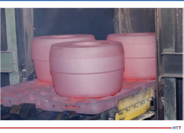
Large Rolls on Their Way into IQ Tank (Source: Joe Powell)
Again, what they were looking for was a longer life valve seat, not necessarily a lifetime valve seat, but something that would last for all of the stages used by that pump at a certain well. They would move it at the time that the well completely fracked and started to produce and take it back and rebuild it at their shop. They were shooting for 200 hours.
DG: Right. Again, the normal was 40-60 hours with the 8620 material.
JP: Right. Having had the experience with the elongator roll and the ability to make something that was literally so hard they couldn't knurl it, we had to temper those elongator rolls back quite a bit in order for them to knurl them and then use them at the mill. I thought, if we don't temper the valve seat back and just leave it that hard, it should be carbide-like hard, because if a carbide tool can't knurl it, it's pretty doggone hard. We fired up our existing piece of equipment that we had at Akron Steel Treating, a 6,000-gallon intensive quenching tank. We heated the parts and quenched them in that big batch tank, and we got very nonuniform results.
One of the things we did not understand back in 2012 was that ductile iron, because of all the graphite particles that are in there, has a very low thermal diffusivity, meaning that in order to get the heat into it or out of it during the quench, you had to be more than intensive; you had to be, what I call, instantaneously impacting that surface with high pressure water that literally pulls the heat out at a rate that will allow you to get to the martensite start temperature, cool to the martensite start temperature, and form that shell in less than 2/10th of a second – and you have to do that all over the part surface to create that shell. This required the making of some new induction heating equipment that have an integrated quench system built into it. This integrated quench system is going way past the ability of our 6,000-gallon tank with its propellers flowing the water laminally across the surface and literally impacting the part instantaneously after the induction heat is turned off.
DG: I want to mention to the listeners that we'll put a photo of this part in the transcript that we'll have on the website so that they can get a much better sense of what the part is; there are some lips and turns and there is an inside diameter and an outside diameter. As you say, if you're flowing water laminally over this, you're going to be missing parts and you're going to be missing areas of the part, so you need to get it quenched quickly.
JP: They actually did crack in the O-ring groove and under the flange out of our 6,000-gallon tank, so we knew we had to do something different. The first thing we tried was to put in the flange and the O-ring groove after it was heat treated, but that wasn't going to work because the part-maker didn't want to have to machine it twice. We had to come up with a way of delivering that water all over the shell of that part and also keeping the core relatively ductile. We didn't want to harden it all the way through and make it brittle, so that's what we came up with while working with the folks at Induction Tooling in North Royalton.
DG: So, it was basically an induction heat and an integral induction quench, very high impact, instantaneous, probably way beyond what anybody else has seen. Describe very briefly, what kind of horsepower was needed to go into the quench.
JP: We used a 60 gallon/minute pump for the ID and a 60 gallon/minute pump on the OD. Both pumps were operating at 60 psi, so there is quite a bit of pressure and quite a bit of flow over a very, very small area.
DG: Which is exactly what needed to be done. So, talk about the results. You're hinting at them here, but what are we talking about in regards to Rockwell hardness and that type of stuff?
JP: We're getting 60+ Rockwell hardness. Again, you've got to remember that this is an apparent hardness because the Rockwell machine is fooled by the very soft graphite particles that are in the matrix. You have very, very hard martensitic iron and carbon in the surface, but you also have these little particles of spherical graphite, and that graphite acts as, what we believe, a lubricant. We haven't quantified it in the valve seat, but we've quantified it for some dies that gives lubricity that's not present in a steel part. The graphite lubricates whatever is traveling over the surface of the part. The other thing that we learned is that the compressive residual surface stresses, when tested by x-ray defraction, are about double that you get when you do carburization of the 8620 valve seat. The very high residual compressive surface stresses also hold those grains of iron carbides in place and does not allow them to abrade or erode. In the first testing, we had three seats that went out to the field somewhere in west Texas, and they lasted 166 hours. We were almost there.
So, we've modified the quenching system, we've modified our heating recipe on the induction tooling, and we made another set of valve seats which we are currently sending out for more field testing. We hope we're there and we'll see what happens. But we literally created a new material. The history of ductile iron goes from as-cast to austempered ductile iron and now, what we call, instantly quenched ductile iron or IQDI
DG: Nice. It all sounds very, very interesting, but I can see some people listening to this saying, “Ok, how much is this going to save me?” Let's talk about the ways that this process saves money. In my mind, you've got a shorter processing cycle time, you're using less expensive material, and you're getting a longer life. Are those the three major ones?
"With the valve seat, the forging and the 20 hour carburizing cycle are eliminated, and it’s machined three times faster. One customer let slip that they were saving about 66% on the material cost."
JP: There is also one other and that is ductile iron because those graphite particles machines about three times faster than steel. So your through-put in your CNC machine goes up by 2 or 3 times when you're making the part and that is no small matter. Also, because the quench is so impactful and so uniformly impactful, it sets the part and you literally get a part that quenches to fit. Once the green size before heat treating is adjusted, the part may not need much, or if any, final grinding.
DG: So, you're saving on post heat treat processing, as well.
JP: Right. And, because we use no oil, we don't have to wash the parts and we don't have to worry about disposing of quench oils or about quench oil fires. And, the process can be done in the machining cell, so it's an in-line process versus a batch carburizing process that has to go someplace for 20 hours to be carburized.
DG: Significant. I think you threw out a dollar figure when we spoke about this previously. What are the savings per valve seat?
JP: With the valve seat, the forging and the 20 hour carburizing cycle are eliminated, and it’s machined three times faster. One customer let slip that they were saving about 66% on the material cost.
DG: Wow. Significant cost savings is the point, so something worth looking into. We're going to have one more episode where we talk about another example. What do you think we'll talk about in the last episode?
JP: The integration of heat treating into the forging process.
DG: Alright super. Thanks for being with us, Joe. It’s always interesting and intriguing.
JP: The integration of heat treating into the forging process. The forging industry association sponsored a project with IQ Technologies. Akron Steel Treating is a member of the forging industry technical committee and has been for years, and we've always thought that there should be a closer alliance between forgers and their heat treaters. We're going to take the information that we gained from this 4 year project, the published final report will be on our website, and we're going to try to commercialize that for a lot of different parts.
Heat Treat Radio host Doug Glenn continues his conversation with AMS2750F expert Andrew Bassett. This time the pair discusses Revision F changes to System Accuracy Tests (SATs).
Below, you can either listen to the podcast by clicking on the audio play button, or you can read an edited version of the transcript.
The following transcript has been edited for your reading enjoyment.
DG: We are back today for our second episode of a three-part series with Andrew Bassett. Andrew is the president and CEO of Aerospace Testing and Pyrometry, headquartered out of Bethlehem, PA, with offices across the county. They do a lot in pyrometry services and related things. Andrew also had a seat on the committee that was responsible for – that owned – the AMS2750 revision F, so he can speak with firsthand knowledge of some of these changes.
If you are interested, you can listen to the first part, which dealt with the major changes in thermocouples and sensors, major changes in instruments, major changes in calibration, and then we also spent a little bit of time right at the end of the last episode talking about offsets.
AB: Yes, and the offsets were one of major changes that we, as a team, did a very good job of spelling out the new requirements for the two different offsets: modification offsets and correction offsets. So that’s a valuable tool to go back and take a look at.
Episode 1 of 3 of AMS2750 series
DG: If you didn’t catch that first episode, you can certainly do that. You can go to www.heattreattoday.com, jump back into the radio section which is under heat treat media on our main navigation tab, and check that out. It would be very worthwhile.
Before we jump into the topic for today, which is the system accuracy tests (SATs), I wanted to ask you a question about this revision. Often, the AMS folks will come out with a minor modification, or not a huge modification, let’s say; other times, it’s pretty much a re-write, end to end. How would you classify this revision F? Where does it fall on that scale?
AB: It leans towards the side of a complete re-write. I think one of the big things that changed was obviously the number of pages of the document; it jumped from roughly 43 pages up to 54 pages. We expanded the number of tables that were from revision E, which had 11 tables, into 25. This was to do some more clarifications of the requirements, or to spell things out a little bit more. I would be leaning on the side of this as being more of a complete re-write. There’s going to be quite a bit in there that is the same old stuff from the previous revisions, but there is quite a bunch of new stuff.
I would lean towards saying that this was a complete re-write and that’s why there were no change bars associated with the spec. Typically, when these specs get revised, the change bars show you where the changes are, but since this was more of a re-write, we left out the change bars this time around.
DG: Instead of having someone go in and “cheat” and just look at the change bars, you’ve got to pretty much start from the beginning and go straight through.
Where do you see some of the major changes in rev F on the overall or the resident SAT?
(source: Andrew Bassett, ATP)
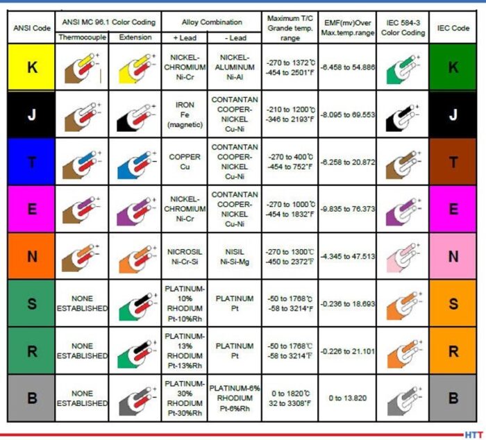
AB: Not a whole lot completely changed on the resident sensors. We still allowed for the same sensors as we did in the previous revisions, where you are limited to different types of sensors based on the temperature ranges, that they were going to be seeing. For instance, if you’re above 500 degrees Fahrenheit, then you’re going to be limited to type N, S, R or B thermocouples, and if you’re above 1,000 degrees, they would have to be what’s called a nonexpendable thermocouple, the metal sheathed type thermocouples. We left that stuff alone. But one of the things we did allow for with the new resident sensors, which I believe is a benefit to the supplies that are using the resident sensors, is that we’re going to allow for some things. Let’s say you have an over temperature sensor, and you also want to use that as your resident sensor. Now you’re allowed to do that as long as you follow the guidelines that say a resident sensor has to be replaced. If it’s a base metal thermocouple it has to be replaced every 90 days, or on a quarterly basis. If it is a noble metal, one of the type R, S, or Bs, it would have to be replaced or recalibrated every six months. We did allow for cases where you have an extra sensor that is being used in dual roles (that is, a resident sensor that also functions as a high limit protection), then you can go ahead and do that. I think that that is something that is beneficial to the suppliers, in that we don’t have to go out and put a third sensor into a furnace or drill a hole to put our resident sensor in.
The one thing that we really want to emphasize with these resident sensors is that their position is to be verified during the installation process and when it’s replaced. When a resident sensor is in a fixed position, we want to make sure it is not moving. Typically, you see a compression fitting that is going to tie the thermocouple down and lock it into place. We want to make sure it is not moving between tests. So, now when you replace these things, you must verify the positioning when you put it in on a replacement basis.
Also, it’s always been the requirement to put the thermocouple in for the 90 days or 180 days, and leave it in there. We’re going to allow you to take it out between the tests, but only as long as it is verified after every single time it’s replaced. I’m not a big believer in that; just because someone from Quality doesn’t come out and verify it doesn’t mean that it could be in the wrong position. But we are allowing you to independently move this thing in and out between the test if you want; that is acceptable. You still have the same replacement periods as quarterly and 180 days depending on the sensor type. We did give a little leeway on that from the resident sensor standpoint. Again, we didn’t make a whole lot of changes on it. We just wanted to spell out the little bit of differences allowing for other types of sensors to be used, or have a dual purpose, I should say.
DG: Let’s move on to the second issue, and that is the alternate SAT process, which I know has sparked a lot of questions with the articles we’ve had on our website. We’ve always had people asking about what they can do, what they can’t do. Let’s talk about that.
AB: Sure. The previous revision in rev E was kind of this dark black hole of what the alternate SAT process was all about. Finally, it was more spelled out in what’s called the “PyrometryReference Guide.” That’s the document that NADCAP puts out, the “pyrometry for dummies,” so to speak. This is basically their interpretation of AMS2750. And then kind of evolved that into what’s called a “heat treat audit advisory.” There were different interpretations of this alternate SAT which were too conflicting to the suppliers. We said, “Let’s make it more clear-cut of what the expectation of this alternate SAT process is.”
First off, the process applies to load sensors that are used once, or for any other type of sensor control or recording sensors that are replaced at the same, or less frequent than the normal, SAT intervals. One of the things that was in the previous version, which we kept, is that the calibration must be performed from where you connect the sensor. Then, once you do that calibration, one of the following three options have to be met. Option 1 is that we take the sum of the sensor calibration error. That’s when you first complete calibration from the point of connection and run through the whole system, including the connections, the lead wire, and the instruments. Then, you document those results and algebraically add that to the correction factors or the errors of the wire either being used or replaced more frequently, and if the sum of those two correction factors are within the allowable SAT tolerance of AMS2750, you would have to document that. And that’s the first option; it’s basically a math function; it’s sitting at your desk and taking the calibration report of your process instrumentation, typically from the recording, and adding it to the wire that’s being used. If you fall within that certain table of AMS2750 for SAT tolerances, you’re good to go. It’s kind of a “desk SAT,” as they call it.
The other way of doing this is to use the appropriate sensor and instrument calibration correction factors. You can either program them into the system or apply it manually as allowed by the limits in AMS2750. Basically, you’re taking the correction factors for the instrumentation that you have calibrated and the sensors that you have calibration “certs” on, and programming that into your system. Again, as long as that meets within the applicable table of AMS2750, that is the second option that is allowed. Because you’re basically using the correction values from the calibration reports for your instruments and your thermocouples, you will always be within your SAT requirements.
The third option allows you to do a couple of things. For one, you can limit your instrumentation calibration error. A company comes in and does your calibrations, and the supplier says they don’t want any of their channels to be more than one degree out of calibration, so, you adjust the instrument calibration to be within that limit. Or, you can specify when you purchase thermocouples wire that you won’t take any thermocouple wire that is no more than two degrees out throughout the whole range you need them calibrated. In that instance, you will always be compliant to the requirements of the SAT tolerances. So, if you restrict the calibrations and you restrict the error on the thermocouples, then you will always meet that requirement. All you would have to do is show, for documentation purposes, the instrument calibration reports that say it is all within 1 degree and all of the wire certifications are within two degrees, and that will always meet the most stringent requirement for SAT tolerances. As long as that documentation is there, you will be able to show compliance to the requirement.
[blockquote author=”Andrew Bassett” style=”2″]“Before, there was no requirement of how to document all this, so we actually put in some hard requirements down on how to document the alternate SAT requirements.”[/blockquote]
Those are the more defined options you have. Before, if you gave it to 100 different people to read, and they said, “I don’t know what to do with this information.” Well, now we’ve put out what we actually meant and defined it a little further now.
DG: Great, so that covers the first two that we wanted to talk about – the overall of the resident SAT and now the alternate SAT – so let’s wrap up with this SAT waiver, which is obviously of interest.
AB: First, I want to jump back real quick into the alternate SAT. We finally added some documentation requirements. Before, there was no requirement of how to document all this, so we actually put in some hard requirements down on how to document the alternate SAT requirements. You have to list out the thermal processing equipment (you have to identify which furnace you’re doing this on), what is the sensor system that’s being tested, and what sensor or roll of wire that’s being replaced. You also have to identify the reason why you’re doing the SAT; for example, because you replaced the thermocouple after every run, something simple like that. If you’re doing the full calculation method, then you’d have to show all your calculated methods. We did finally put some teeth in to help you document this well.
DG: Now, the SAT waiver. Tell us about it.
AB: In all my years out in the field of pyrometry, I rarely found many suppliers that did this SAT waiver correctly. We didn’t change a lot of the basics of the requirements, but we did change some new requirements regarding how to gather your data to make sure that you do this correctly. We still require that if you’re using noble metal load thermocouples, which are the platinum based thermocouples, you replace and recalibrate them on a quarterly basis. If you have base metal load thermocouples, if they are expendable, they should still be just a single use. If they’re nonexpendable, sheath type thermocouples, they shall meet the requirements of Table 6 in AMS2750F, and that gives you guidelines of how often those need to be replaced.
If you have any kind of observations that are made and recorded on at least a weekly basis and which reveal any unexplainable difference between observable readings and readings of two recording sensors, this is where the change really occurred on those two additional sensors. We spelled out that these weekly readings have to be conducted at one production setpoint and measured within the five minutes at the end of the production soak period. What this weekly log is supposed to be doing is to compare one sensor against another sensor that you’ve identified.
Some people have used the control sensor as the one sensor and, let’s say, the high limit thermocouple as the second sensor. These have to stay within a two-degree relationship from the last successful survey, and so people were wondering when they were to take the weekly reading. We decided to spell this out a little bit further: this weekly reading must be done at production setpoint and measured within the minutes of the production soak period. In other words, you can let your thermocouples soak out for a period of time, during which you can complete your comparison check. These have to be within two degrees of the relationship determined at the most recent TUS temperature and at the nearest temperature tested during the most recent TUS.
For example, let’s say we do a survey at 1600 degrees and the control is reading 1600 degrees and my over temp is reading 1602. Next week, we come along and we’re running a job here at 1500 degrees and my control is reading 1500 degrees and my over temp is reading 1501, you’re good. You’re within that two-degree relationship. That’s where this two-degree relationship needs to occur.
But the one thing that we’ve done now is we’ve asserted that the two sensors have to be different types. Before, you’d have, let say, two type S thermocouples in your furnace; you can’t have two type S thermocouples now. You have to make a different thermocouple type for the relationship. This is more to catch any drifting of your thermocouples over time. For instance, if you had a type S thermocouple in your furnace as your control, you’re going to have to be limited to either a type B or type N thermocouple as that secondary sensor that you’re doing your relationship check with.
That’s what a big change is. Before people just used the two same sensors. What we were concerned about is – and let’s say those two thermocouples were made from the same lot of material – that there is a good chance that when the thermocouples start to drift, they’re going to drift in the same direction.
Again, we did put some similar restrictions on resident thermocouples. For the example I used, if you had type S control thermocouple, you’d be limited to type B or N, but we also allow for R as that extra thermocouple. But R and S are very similar in the chemical composition makeup, so we don’t allow an S to go against an R and vice versa, in that case. If you had a control thermocouple that was K, then really any other thermocouple that is allowed once you’re above 500 degrees you’re limited to the B, R, S, and N. Actually, these requirements are exactly the resident sensor requirements as well.
DG: Anything else on that SAT waiver?
(source: Andrew Bassett, ATP)
AB: We do now have some documentation requirements, too. Again, before there were no requirements there. Now you have to list the equipment that you’re doing the waiver on, you have to identify the control sensor, what type of sensor it is, plus what the additional sensor is used for the sensor relationship test. You have to list out the date of when the control and the additional sensor to be used, when they were installed, and when they were replaced or recalibrated. You have to list out the run number and date, so that when you are completing the production cycle on a weekly, you have some kind of easy identifier to tell you that it was done on run #ABC123, and the date was 9/8/20, so we can go back to the records and verify it. Date and temperature of the recent TUS and the documentation, that weekly log, are necessary; we need to see that weekly log as well.
We finally put some teeth into the requirements of the SAT waiver. I don’t think it’s going to be a big change for a lot of the suppliers out there. They will have to change over that one sensor, but, for the most part, I think we tweaked it enough where we felt more comfortable, especially changing those two different sensors so that we didn’t have drift occurring at the same time. That was our biggest concern as a committee.
DG: So, you’re basically trying to ensure reliability and you’re going to actually test for what you’re testing for. That makes sense.
We talked briefly about the overall or resident SAT, the alternate SAT, and the waiver. If you, the listeners, have questions, be sure to email them into us and we can potentially get Andrew to respond to them. Send those to htt@heattreattoday.com. We’ll leave Andrew’s information at the end of each of these podcasts.
Andrew, I’ve got a final question for you, not dealing with any specific aspect of the revision, but just to give people a sense of the amount of time that folks in your shoes, people that have invested time or actually on the committee: How much time do you think you’ve invested in the rev F portion of AMS2750?
AB: It was a long process. To put it in perspective, we developed our sub team and had our first meeting back in October of 2017, during one of the NADCAP meetings. We were kind of on a fast-track to get this spec revised and put out there. It wasn’t actually released until June of 2020; so three year plus is a fast-track in the eyes of the AMS world. We did meet at least six or seven times a year, either during an AMEC meeting or during one of the NADCAP meetings, and we had numerous Webex calls. When we actually met face to face, they were good 8 – 10 hour sessions of hammering out the spec. Then, we would take it back to our own groups and muddle through what we discussed. It was a long period of time. I would hate to put an hour on it. I wish we’d gotten paid for that! Taking into account what our company is and what we do, we have to live, breathe and eat this spec, day in and day out, for our customers. I just wanted to be a part of the process of getting this documentation, so the world can understand the issues in pyrometry.
DG: I actually have one other question for you. You told us in the first episode how you got onto the committee. Are they always looking for people to participate on the committee, or do they carefully fence that and only invite in certain types?
AB: Anybody can be a member of AMEC. So anybody that wants to get involved with the revisions of any of these specifications, including the AMS2750, they’re more than welcome to show up at an AMEC meeting, get involved, and volunteer to get involved with the specifications. I remember my first meeting where the chairman said, “You’ve got to get on this 2750 team. And, oh by the way, we’re thinking about writing some other specs that we’re going to throw you under the bus for.” They’re looking for young blood to get involved with these specifications and be a part of it, so yes, anybody can get involved with these specifications.
DG: If you are listening and you’re one of those people that might be interested in participating in that, you can certainly get a hold of Andrew.
This was our second part in a three part series. Our last episode will be on temperature uniformity surveys, the issue of rounding, and quality assurance provisions. If you’d like to learn more or reach out to Andrew, you can go to www.atp-cal.com and look at their ‘about our team’ section in the main navigation bar. I’d also be happy to receive emails on behalf of Andrew. My email is doug@heattreattoday.com. Thanks for listening.
Doug Glenn,Heat Treat Today publisher and Heat Treat Radio host.
To find other Heat Treat Radio episodes, go to www.heattreattoday.com/radio and look in the list of Heat Treat Radio episodes listed.
In this first of a three-episode series on AMS2750F,Heat Treat Radiohost, Doug Glenn, discusses Andrew Bassett of Aerospace Testing & Pyrometry discusses the significant changes in the specification in the areas of thermocouples and calibrations.
Below, you can either listen to the podcast by clicking on the audio play button, or you can read an edited version of the transcript.
The following transcript has been edited for your reading enjoyment.
Doug Glenn (DG): This past June AMS2750 released revision F, but what does that mean to you? We caught up with AMS2750F committee participant, Andrew Bassett, to find out. Our conversation about this revision will stretch over 3 episodes with the first dealing with thermocouples and sensors, the second dealing with system accuracy tests and the third, temperature uniformity surveys. This first episode will be all about thermocouples, sensors and calibration.
Andrew, welcome to Heat Treat Radio. We're excited to have you to discuss this AMS2750F revision. If you don't mind, why don't you take a minute and introduce yourself to our listeners?
Andrew Bassett (AB): I'm president and owner of Aerospace Testing & Pyrometry, headquartered out of beautiful Bethlehem, Pennsylvania. I've been in the aerospace pyrometry field for going on 30 years, after graduating from college at Davis and Elkins college in Elkins, West Virginia with a degree in communications. I discovered by myself that I would end up starving in radio broadcasting, which my field was, and got involved with a company called Pyrometer Equipment Co., a family owned pyrometry business. They needed some help as they were expanding operations, and it was the father of my girlfriend (at the time)—now my wife--who had started that business in 1956. That's how I got my break into pyrometry.
Davis and Elkins College (photo source: dewv.edu)
This was also the time when NADCAP was starting to put its foothold on the aerospace industry. I kind of self-taught myself in the ways of aerospace pyrometry. I spent many years getting to know the specification and understanding what the requirements were, dealing with the auditors themselves, and having them teach me about what they look for during audits. I've taken that knowledge with me for the last 26 years.
After I left the family business, I worked for another start-up company in the field of pyrometry, left that company, and worked for a large commercial heat treat company based in the Southeast as their pyrometry director. At that time I started to feel like I wanted to start my own pyrometry business. So, in 2007, I started Aerospace Testing and Pyrometry (ATP). I was doing it part-time for a while, but then in 2009, I decided to go full force. To this day, it is not just me anymore: there are 16 of us in the company which is spread from coast to coast to take care of pyrometry services as well as other things we have branched off in with ATP. I call it our four headed monster. We have our pyrometry services, which includes calibration and testing of thermal processing equipment. We do get involved with other testing as well, like vacuum measuring systems for vacuum furnaces. We've also done humidity pressure gauges and gotten involved with different types of calibrations as well. Additionally, we have our laboratory, which is based in Ohio, where we do calibrations of secondary standards and field test equipment. Finally, we have our consultant and training arm, with which we have a full-time ex-NADCAP auditor on staff who is able to assist our customers with pre-assessments of NADCAP audits.
AMS2750 is the main aerospace material specification in pyrometry. If you actually try to do a Webster's Dictionary search on pyrometry, you'll find it is a made-up word. We've interpreted it as the calibration and testing of thermal processing equipment; that is, heat treating equipment and any type of thermal processing will fall under this specification when it comes to testing.
AMS2750 has also now been adopted by others; it is not just a heat treating specification anymore. Two years ago, the FDA adopted AMS2750. Those facilities that are heat treating medical implants or dental drill bits will now have to follow the requirements of AMS2750. The one industry that walked away from this specification is the automotive industry. They have their own requirements called CQI-9. I always make a joke that the one good thing about AMS2750 in dealing with aircraft is that we don't see planes falling out of the sky, but we do see a few more recalls on automobiles and automotive parts.
DG: Just as a little preview for our listeners, Heat Treat Radio will be doing probably a two to four-part series, similar to what we're doing here with Andrew, on CQI-9, so stay tuned for that.
Andrew, how exactly did your company get involved with AMS2750?
AB: So, they had started to revise—and this goes back several revisions ago—revision C to create revision D. Revision C, I always said, was the Bible: You can give it to 100 different people and you would get 100 different interpretations. It was a much-needed change that was needed in revision D. At this time in my career, I only had about 8 years experience in pyrometry, but I had to live and breathe this document day-in and day-out. So, I approached several members from the AMS2750B team to get involved with the spec. I didn't have the great experience like some of the other members of the team who were from Boeing, Bodycote, and Carpenter Technology and other folks, and they said, “Well, we kind of have our team set into place. We'll ask you questions if we need anything.” I didn't hear much from them, but one of the team members did keep me posted of some of the changes.
Then when it came to the rev. E, I heard rumblings that they were going to revise the spec again, and it was at this time that I decided to attend an AMEC meeting. AMEC is basically the think tank of all of the AMS specifications that are dealt with. AMEC stands for the Aerospace Metals Engineering Committee. The various segment specifications fall under various commodity groups, I believe it's A thru H. AMS2750 is actually owned by committee B for NSAE. So AMS guys write the specifications, the commodity committees own the specifications and that's how this process works.
I did attend my first AMEC meeting and the chairman at the time was a gentleman from Lockheed Martin. Anybody can join the AMEC meetings and be a part of them, but at that meeting he asked who I was and my background. I told him and said that I wanted to get involved with this specification and he said, “By all means you need to get involved with this specification. Since you do this for a living, I think we'd like to have that perspective.” So that's how I got on the AMS2750 team for rev. E. I'm still young enough, and dumb enough, to keep going on to this revision of rev. F and will probably be around for the next revision after that.
I did have my inputs in both the specs. We had a great team for rev. F which included myself, Doug Matson from Boeing, who has since just retired, Marcel Cuperman, who is a staff engineer for heat treating for PRI NADCAP, Cyril Vernault from Safran Aerospace, (he is also the heat treat task group chairman in NADCAP), Brian Reynolds from Arconic, Douglas Shuler from Pyro Consulting and a NADCAP auditor, and James LaFollette from GeoCorp. Our team has consisted of people across various parts of the industry. From Arconic’s standpoint, we were looking from the raw material producers. Obviously, with GeoCorp, it was from the thermocouple side of things. And from Cyril Vernault based in France, we wanted the European influence of what's going on over there. So, a good, broad range of people from various sectors of the industry are involved with the specification.
[blocktext align="left"]“I'm an end-user, so I'm able give my input and say, ‘Hey, this doesn't make sense. What you want to add into the spec is not real world.’”[/blocktext]One of the things I always had in my mind when I first got involved with the specification was that the specifications were written by the aerospace "primes," but that's not the case; it involves people, such as myself, who are end-users of this specification. I'm an end-user, so I'm able give my input and say, “Hey, this doesn't make sense. What you want to add into the spec is not real world.” It’s nice that people such as us get involved with these specifications.
DG: Let's talk about the main sections of this specification. If you break them down, what are the main sections?
AB: There are really only five sections of the specification. You can break it down into thermocouples, calibrations and thermal processing classification, SAT (system accuracy testing), TUS (temperature uniformity surveys), and the very last five or six paragraphs are on the quality provisions (what happens if you have a failed test). Those are the 5 main sections of AMS2750.
DG: So focusing on the topic of this episode, thermocouples and sensors, let's highlight some of the profound changes that have been made in rev. F. First, what are the biggest changes regarding thermocouples and sensors?
AB: The bigger changes relate to how we address some different thermocouple types that were not addressed in previous revisions of the spec. In rev. F, we added and gave a thermocouple designation, type M, to Nickel/Nickel-Moly thermocouple. These thermocouples have been around for a long period of time. We do know that they're being used in aerospace application, especially at very high, elevated temperatures. It's more cost-effective than going into the platinum or the noble-based thermocouples. Type M was one of the newer thermocouples we added.
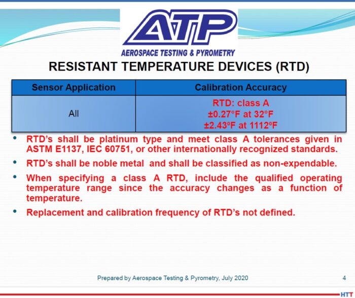
We also addressed the use of RTDs, which is, again, something that we had seen in the aerospace industry for quite a while. As I mentioned before, this is also a crossing over from the heat treat world into the chem-processing world. A lot of these chem-processing tanks use RTDs to measure chem temperatures, so we thought we better address these type of thermocouples.
RTDs in AMS2750F explained (photo source: Andrew Bassett, ATP)
Then we also added refractory thermocouples, which people weren't all that familiar with, unless you're dealing with the hot isostatic pressing (HIP) process. We're seeing more and more of the HIP furnaces out there now, with all of the additive manufacturing that is going on. We see people adding HIP furnaces everywhere, and a lot of those HIP furnaces are coming with type C thermocouples, because they are rated for these elevated temperatures that the HIP processes do. I think the type C thermocouples are rated close to 4,000 degrees Fahrenheit. We had to add some of these extra sensors that have been around for a while, but we wanted to bring them out a little bit further.
One of the other changes that was pretty significant—though I don't think it will affect the industry all that much—is that now we require thermocouples to be accurate to what's called “special limits of error.” The previous revision allowed for two different types: You were allowed special limits of error, which the accuracy is + or –2 degrees Fahrenheit, or .4% of reading. That was only required for a system accuracy test sensor or for a sensor that was being put in a Class 1 or 2 furnace. All other sensors, such as TUS of load sensors, and class 3-6, we allowed for standard limits of air, which was + or –4 or .75% of reading, whichever is greater.
We did some polling of major thermocouple suppliers out there. With my personal experience and that of some of the other people on the committee, we kind of said, “Hey, you know what? No one really orders the junky stuff, the standard limits; everyone orders special limits of error.” James LaFollette said, “Come to think of it, I don't think I've ever seen a purchase order that says give me the crappy stuff. We all order special limits.” So that's what we discovered – that no one was ordering the bare minimum because there wasn't a price difference between the two. Everyone had already been ordering the good stuff, so we just made that a little bit of a tighter requirement. Again, I don't think it's going to affect any suppliers out there.
I think the biggest change, when it came to thermocouples and sensors, was a big restriction that we put on what's called “expendable test sensors.” This was dealing with the base metal thermocouples. Base metal thermocouples are type K, type J, type T, type N, type M, and a couple other type base metals.
Click to read the Heat Treat Today article on thermocouples.
Primarily in the heat treating and thermal processing world, you pretty much see the K, J, N, and T. We had done some studies as a sub-team within 2750 to look at the drifting of thermocouples, that is, where thermocouples start to lose their accuracy. In the previous revision, we had some provisions in place that allowed people to use these expendable thermocouples that were attached to a temperature uniformity survey rack and were preserved. They could use them up to three years or 90 uses when below 1200 degrees. We thought that seemed kind of excessive on a 20-gauge wire that is covered with fiberglass coating. They're probably not going to hold up, but maybe we should see if there is any drifting of these thermocouples. So, we had one of the major thermocouple suppliers, Cleveland Electric Lab, run some drift studies on type K thermocouples, and we found out that these wires were actually starting to drift after three or four runs. The drift study included a cycling test where they ran it up to temperature and back down 30 different times. We asked, “Why don't we try to simulate how these thermocouples are going to interact coming in and out of thermal processing equipment? Why not pull them out every single time and do it that way?” Again, we found that thermocouples were drifting even further and even quicker.
At this point we decided we better put a restriction on this, and that gave the biggest uproar regarding the reuse of these thermocouples. Previous drafts before the final release of the spec was, if it's used above 500, your expendable wire is one and done above 500 degrees. A lot of the suppliers out there came screaming and said this is going to cost us millions and millions of dollars more in thermocouples. But we stood firm and said, “Hey look, if you're using these test thermocouples to validate your furnaces, either through a system accuracy test or uniformity survey, you really do not know what your error of that wire is after the first use.”
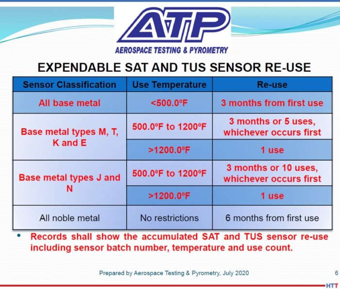
Most of the major thermocouple suppliers will even state on certifications that they will only guarantee accuracy at the time of calibration. Once it goes in a furnace, atmosphere and different conditions of the furnace will affect the wire. We stood our ground, but we ended up backing off a little bit. If you were using them strictly below 500, you're allowed to use them for 3 months (90 days) and you're going to have to keep a log. If you're using them between 500 and 1200, we're going to allow you to use them for 90 days, but now you're only restricted to five usages. And then again, above 1200, you use it once and throw it away. That was probably the biggest hassle, trying to get that. We did finally compromise on that three month or five usages. I do see the burden on the suppliers because they were used to three years or 90 usages, so now it's down to three months or five usages.
DG: I see on the chart that I've got here in front of me that base metal types of M, T, K, and E are all the three month or five use, but you've also got base metal type J and N which is three months or 10 uses. But all of them, above 1200, one and done.
Table for SAT and TUS Sensor Reuse (photo source: Andrew Bassett, ATP)
AB: Correct. That's one of the things I was trying to explain to some of the suppliers that were having heartache about the original change of 500 one-and-done. We only left it to the types M, T, K, and E; we always left this out of types J and N. My personal experience with type J has been (and we've switched over to type J wire a while ago for testing below 1200 degrees),that it's a little bit cheaper in price than the type K wire, and there was always this allowance for doubling the amount of usage if you just switch over to type J or type N.
DG: We have a few significant changes in the area of calibrations. What's another area of change in this section?
AB: One of the big things which really surprised me when we wrote it into the standard, but which was kind of overlooked by some of the suppliers, was the requirement of test instruments to have a .1 readability. So when it deals with test instruments and also now data acquisition systems. Now, if you have a chart recorder that is on your furnace (most people are going to data acquisition systems, some sort of SCADA systems), that recorder must have a .1 readability. That caused an uproar since that may create big changes.
Now, we don't put out these changes because we think it's a good idea; AMEC is data driven. The big thing with the .1 readability is that we were actually fixing a flaw that has been in the spec since the first day it was written, when it was just rev. A. We allowed for percentages of readings for your accuracy requirements. Let's say, for instance, on your instruments that are on your furnace calibrated controller an if it's in Fahrenheit, you're allowed + or –2, but if it's in Celsius, it has to be + or – 1.1. And if your instrumentation doesn't show .1 readability, how can you show compliance? That question is one of the reasons—that is, fixing a flaw in specification.
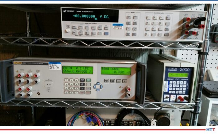
(photo source: www.atp-cal.com/laboratory/)
But we also allow for percentage of reading, which is + or –2 Fahrenheit or 1.1 Celsius or .2 % of reading, whichever is greater. Let's say you have a calibration point at 1400 degrees, you're actually allowed an error of 2.8. If you can't show that decimal point readability, how can you show compliance? That was one of the biggest issues.
Originally, the first draft said all digital instruments need to be .1 readability and then we backed that off to only say that the data acquisition system had to be .1 readability. At the end of the day, the recorders or the data acquisition system is the proof. As long as that shows the tenth of degree of readability, and it meets the requirements, then you're good to go there.
We did look at how many customers are already using digital data acquisition systems through NADCAP. There's actually a NADCAP checklist question that talks about chart speed verification, and if you answer that “N/A” then you obviously have digital data acquisition. At that time, we did look at that data and 78% of the NADCAP heat treating suppliers out there already had paperless systems. On top of that, two years after the release of 2750F, so as of June 29, 2022, you're not allowed to have paper chart recorders anymore. Everything is pushed to a digital data acquisition system 2 years after the release of this spec. I'd say, that's another one of the bigger changes when it deals with the instrumentation.
So the biggest changes are the .1 readability for your chart papers and the two years after the release requirement to go with a paperless system.
DG: Now question three: What are the changes that were made in the calibration section?
AB: There were a few changes when it came to calibration.
One of the things we added this time was the calibration of timing devices. A lot of facilities have timers or clocks that they're basing their times and temperatures, and again, there was no requirement to calibrate this. Therefore, we added a whole section on calibration of timing devices.
There was some push back on that. Certain people, who have suppliers who use certain control operated by computers and which are always synchronized in their server systems, asked if they were going to have to go out and buy calibrated stopwatches and sit at their PC to make sure it's within these new requirements. We finally said, no, you don't have to do that, but if you can procedurally address how that whole system works—that your server is always verified—you would be okay as long as you procedurally address that.
Again, we were loose on the accuracy requirements. Some of these external devices that you have only need to be calibrated every two years. Comparing it to people's standards that they use—we personally do calibration of timers as well, and our standards are required to be calibrated every two years—we ended up just tossing these devices away because it's more expensive to send them back for recalibration than it is to buy new ones. So, we gave some of the suppliers an easier way out. But we just wanted to address, again, something that has never been brought up in the specifications, which, though not technically dealing in the pyrometry world, does sit on furnaces. We need to get these things looked at every now and then as well.
“So, we gave some of the suppliers an easier way out. But we just wanted to address, again, something that has never been brought up in the specifications, which, though not technically dealing in the pyrometry world, does sit on furnaces.”
Some of the other changes come in the documentation. We did change some things that need to be required for the documentation of your calibration results. One of the things was that we need you to document the sensor that you're calibrating for that particular piece of equipment. For instance, you have a vacuum furnace and most vacuum furnace control sensors are a noble metal type S or type R thermocouple, but then the load thermocouples that measure the parts inside might be set as type K or type N. We just want you to denote that the control system is type S and the load thermocouples are type K. Not real big game changers, it's not going to cause too many issues out there from the supplier base, it's just adding basically another column in your calibration reports to say what sensor you're calibrating.
We didn't go too overly crazy on the calibration portion. The one thing, kind of in the calibration field, is we did add a new instrumentation type. When you look at thermal processing equipment, it's broken down into two different sections. You have your furnace classification which is your uniformity tolerance and then you have what's called your instrumentation type. You have class 1 - 6 and you have instrumentation A – E, now instrumentation D+. This was more for Safron Aerospace. Cyril Vernault was very adamant that we add this D+ instrumentation because Safron's specifications state that they want this extra sensor that is basically 3 inches away from the controlling sensor, so they can measure if there is a big difference between these two sensors to determine if there is drifting of your thermocouples. So we added this new D+ instrumentation. We didn't realize this was big over in Europe, but it was nice to have someone like Cyril say that a lot of European suppliers use this and that he’d like to see it in AMS2750. Again, having this broad range of people on the specification helped us find out what's going on in different parts of the world.
DG: How about we close with the fourth part of thermocouples? Could you delve into the expanded section on offsets?
AB: Absolutely. Always one of the areas, especially when it comes to NADCAP audits, is the use of offsets. We basically broke it down into two different types of offsets that are allowed. We have what's called a correction offset, which is basically either a manual or electronic means to bring an instrument back to a nominal temperature. And we have a modification offset, which is just the opposite. It takes either a manual or electronic offset or a shift in the temperature to bring it away from nominal. There are different ways that people have used these offsets. For instance, let’s say you go into a facility and you're doing your calibration of a controller, and the instrument is off linear by two degrees. People would use the offset to bring the instrument back a nominal temperature. Instead of maybe doing a full factory calibration, they would just go into the instrument, hit some magic buttons, and (say I need to offset it -2 because my instrument was two degrees high) set a two degree correction offset.
A modification offset generally is only going to be used for when you're doing a temperature uniformity survey. Let's say it is skewed to one side of your temperature median. For instance, (I always like to use this in my pyrometry training class), we know temperature uniformity and I go in and do a temperature uniformity on your furnace at 1000 degrees. I have to hold it to be + or –10. When I get my final results and I look at everything with all my calculations, I have a survey that actually comes out to be 992 – 998 degrees. It's well within the + or –10, but it’s skewed down to the lower end.
So, there's different things you can do to try to correct that. Maybe change air flow, or thermocouple location, but a lot of time, what happens is you get a furnace that was made in the 1940s and you're trying to make it comply to 2020 specifications. The only thing you can do is go in and shift the controller away from the nominal to actually make it read hotter. In this example that I'm giving you, what I would do is go in and put in an electronic offset and tell the controller to read colder now, as I will drive more heat into the furnace. So, I go in and put a -5 degree offset into the control and now, in theory, when you do the survey, you're shifting that temperature up by five degrees. Now if you look at that split, it would be 997 – 1003—it’s more centered around your set point temperature. That would be what's called a modification offset. You're taking that TUS distribution and skewing it to better center around the set point.
We really did some “spelling” on this: we put some maximums, the amount of offsets that are allowed as we don't want people to go too crazy on these things, so we did put some offsets in there. But I think we did a great job of trying to spell out what these offsets are being used for, how you're supposed to document them, and make sure that you're consistent with your practice every time. Again, procedures will have to be written to fully understand how you're going to do the offset. Am I going to put it electronically? Am I going to do a manual offset, just shift my temperature up five degrees because I know my furnace is cold by five degrees? I think with that whole new section in there, I think we did a good job of spelling that out for the suppliers.
DG: Thanks so much, Andrew for joining us on the podcast.
AB: Thanks for having me, Doug. Looking forward to chatting more with you about AMS2750F.