

How 3D Printing Coils Exceeded R&D Expectations

In this Technical Tuesday installment, Josh Tucker, manager of Induction Heating, Tucker Induction Systems, Inc., relates new research conducted on the strength of coils which have been produced through 3D printing.

This informative piece was first released in Heat Treat Today’s April 2025 Induction Heating & Melting print edition.

To read the article in Spanish, click here.


Research on 3D printing induction coils finds that coils are stronger and have a longer life when compared to traditionally manufactured coils. Read about how additive manufacturing removes steps like brazing the joints and provides new design capabilities. 

Tucker Induction Systems began exploring the possibility of using 3D printing technology to manufacture coils and found that, in many cases, 3D printed coils were stronger and longer lasting than traditionally manufactured counterparts. 

The quest to develop 3D printed coils began in 2020. When COVID-19 hit, Macomb County, Michigan, started an initiative called Project DIAMOnD, which stands for Distributed, Independent, Agile Manufacturing on Demand. It provided small-to-medium-sized area manufacturers with Markforged Fused Deposition Modeling-style 3D printers as both a way to quickly manufacture much needed personal protective equipment for the pandemic and to help small-to-mid-sized manufacturers overcome the supply chain issues that plagued industry during the crisis. 

We were eager to gain hands-on additive manufacturing experience through the DIAMOnD initiative and, in doing so, found that it sparked our curiosity about the possibility of 3D printing our coils and new ways to design them that go beyond the capabilities of traditional machining. 

In 2021, we began a two-year research and development process of printing coils and discovered that by 3D printing induction coils we were able to drastically increase the strength of the coils and potentially lengthen the useful life of the coil. The experience has opened new realms in designing our coils, as well as giving us the ability to design coils using methods that go beyond the capabilities of traditional machining. 

It is common industry knowledge that the weakest parts of a coil are the braze joints, but through the R&D process, we have learned that by 3D printing the coils, it is possible to eliminate most, if not all, braze joints in the head of a coil. This increases the strength and, potentially, the life of a coil. After years of testing and evolving, the end results were better than we expected, proving that the coils can be printed and will last in the field. 
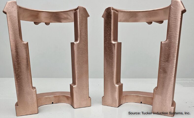
Figure 1. 3D printed single-shot hardening induction coil heads

However, there were some challenges in adapting to using 3D printing technology. For example, the type of copper printing we required was not being done in the United States, which was an obstacle in trying to form a process that resulted in a successfully printed coil. But one of the biggest challenges after we locked down the process and material was in designing the internal cooling passages for the coils. The passages needed to be designed in a way that was self-supporting and non-restricting. We had to produce the same flow rate as traditionally made coils and ensure we were driving the cooling into the right areas. Figuring that out took many failed attempts — learning opportunities — before achieving success. 

Once that goal was achieved, we installed a metal 3D printer at Tucker Induction in January 2024 and have been successfully printing all different types of coils. Some examples include two turn ID, spindle, single-shot, and scanning coils. 

The Benefits of Using 3D Printed Coils 

While traditional coils (such as our interchangeable, quick-change coil for two-turn induction systems and single-shot designs with accurate clamping pressure) have changed the industry, the additional capability of 3D printing allows us to print dimensionally accurate, durable parts that are capable of performing in the field and that can go beyond the barriers of traditional machining. 
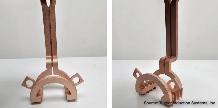
Figure 2. 3D printed single-shot induction coil with keepers

3D printed coils bring several worthwhile benefits to the table including time savings, longevity, and faster coil repair. Time savings is one of the biggest advantages. Because the 3D printer can run “lights out,” the processing time from the printer to the client is far shorter when compared to traditionally fabricated coils. We refer to the processing time as the additional time needed to complete the coil assembly after printing. In some situations, it is possible to print a completed coil assembly with the coil immediately ready to be sent to the client. Other times, additional brazing or supplemental details may be required to complete the assembly. 

Since all coils are different, the processing time varies from coil to coil. However, by printing as much of the assembly as we can, we are able to limit the amount of additional work needed to complete the job. 

Strength and potential longevity of 3D printed coils are additional advantages. The weakest parts of the coil are the braze joints, but the process we use to print the coils drastically reduces the amount of braze joints, thus making the workforce of the coil a solid construction. This results in a product that will be stronger in the induction environment and has the potential to outlast its traditionally manufactured counterpart. 

When it comes to the lifetime of the 3D printed coils, our baseline is that the printed coils need to last at least as long as traditionally manufactured coils. However, in our research, we have seen, on average, that our 3D printed coils can last two to three times longer than traditionally manufactured coils. While the longevity of each coil is case dependent, as there are many factors that go into the lifespan of a coil, one of our original test coils is still running in the field with over one million heat cycles. 

While continuing to improve processes and designs, we are also pushing to decrease the time for repairs. Getting our clients’ coils repaired and returned in an effort to limit their downtime has always been something we strive for with our traditional coils, but we have found that 3D printed coils are easier to repair. Since multiple braze joints are not an issue in printed coils, it reduces the chance of causing additional problems as you work on the original repair. If the repair consists of replacing the head of the coil, we are able to recall the original print and run it again, as opposed to having to re-machine and re-assemble and braze the entire coil, significantly reducing the repair time of many 3D printed coils. 

Limitations of 3D Printing Coils 

Despite the advantages of 3D printing induction coils and the fact that the capability to print coils gets you into the mindset that every coil needs to be printed, there are some instances when it is still more effective to use traditional manufacturing. 

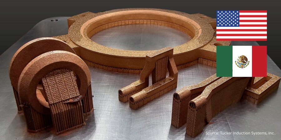
Figure 3. 3D printed sample structures

For example, coils that are larger than the machine is capable of printing — our print bed size is roughly 12 x 12 x 13 inches — can be a limiting factor. Other times, the coil may be manufactured faster using traditional methods. The printer does have limitations, and it is not the best option for certain coils. For example, coils that are less intricate and made from tubing is one type that would be a better candidate for traditional manufacturing; these coils simply require wrapping copper tubing around a mandrel. 

The Future of 3D Printed Coils 

We are continuing to research and fine tune the processes of 3D printing our coils and strive to provide our clients with the best possible product. In order to do that, we must stay vigilant and be willing to continuously learn and improve our designs and processes.  

As we learn more and perfect our 3D printing coil processes, I believe 3D printed coils will play a vital role in the future of the industry. We have proven that 3D printing coils is not just possible, but that in some cases 3D printed coils can outperform their traditionally manufactured counterparts. 

About The Author:

Josh Tucker
Manager of Induction Heating
Tucker Induction Systems, Inc.

Josh Tucker graduated with a bachelor’s degree from Grand Valley State University and was then hired as the head of Purchasing at Tucker Induction Systems. Since starting eight years ago, Josh’s role and capabilities have expanded to machining, wire EDM, 3D printing, and laser engraving. He also organizes the day-today operations and flow of the shop floor. Josh was recognized in Heat Treat Today’s 40 Under 40 Class of 2024.


For more information: Contact Josh Tucker at JTucker@tuckerinductionsystems.com


How 3D Printing Coils Exceeded R&D Expectations Read More »

Boronizing — What Is It and Why Is It Used?

The Heat Treat Doctor® has returned to offer sage advice to Heat Treat Today readers and to answer your questions about heat treating, brazing, sintering, and other types of thermal treatments as well as questions on metallurgy, equipment, and process-related issues.

This informative piece was first released in Heat Treat Today’s April 2025 Induction Heating & Melting print edition.


Of all the case hardening processes, boronizing (a.k.a. boriding) is perhaps the least understood and least appreciated. Let’s learn more.  

In this era of using coating technologies (e.g., PVD, CVD, DLC) to produce hard, wear-resistant surface layers on component parts, one often forgets that there is a thermo-chemical treatment that often can outperform many of them.  

Boronizing (a.k.a. Boriding)  

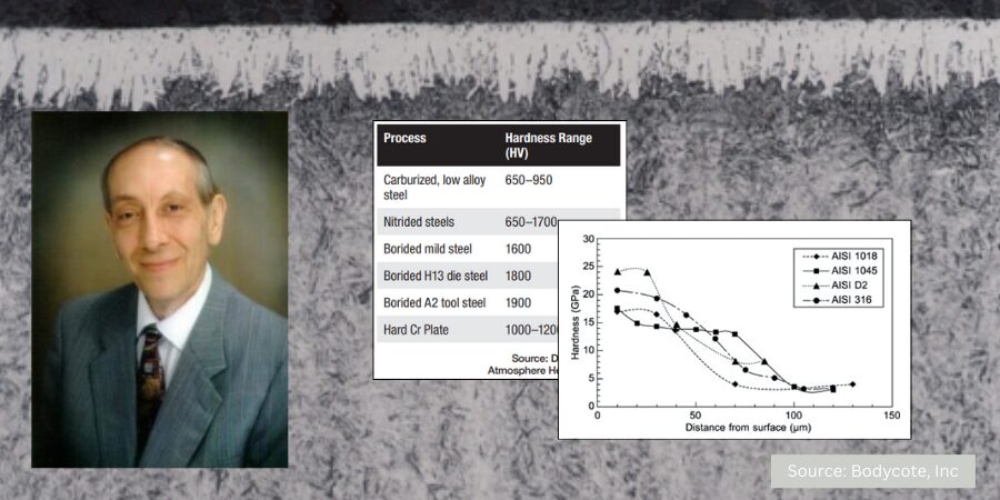
Table 1. Examples of hardness levels achieved by boronizing*
*The hardness of the boride layer depends on the compound formed. For example, FeB is 1900–2100 HV, Fe2B is 1800–2000 HV, while Ti2B is 3000 HV.

Boronizing is a case hardening process that produces a very high surface hardness in steels and is used for severe wear applications (see Table 1). The layer of borides (FeB and Fe2B) formed also significantly increases corrosion resistance of the steel.

Boron is added to steels for its unique ability to increase hardenability and lower the coefficient of (sliding) friction. In addition, boron is used to control phase transformation and microstructure since the time-temperature-transformation curve for the material when boron is diffused into the surface is shifted to the right. 

The Process

The boronizing process is typically run in a solid (pack), liquid, or gaseous medium. Each of these methods involves the diffusion of boron into the steel’s surface, but they differ in how boron is introduced and the conditions under which they operate. 

  • In the pack boronizing, a powder mixture of boron compounds (typically boron carbide or sodium tetrafluoroborate) is packed around the steel workpieces. This pack is placed in a retort-style furnace where it is heated, typically with an argon cover gas, to temperatures ranging from 1300°F to 1832°F (700°C to 1000°C). The heat causes the boron to diffuse into the steel surface, forming a boride layer (Figure 1). 
    • A key advantage of this method of boronizing is that it is highly effective for producing uniform boride coatings. It is particularly suitable for large parts or components that may not be suitable for immersion in a liquid or exposure to gaseous boron compounds. 
  • In liquid boronizing, the steel is immersed in a molten bath containing boron-bearing compounds, typically a mixture of sodium tetraborate and other chemicals. The steel absorbs boron from the bath, forming a boride layer. The liquid process tends to be faster than the solid method and can be more economical for certain applications. 
    • One of the challenges with liquid boronizing is that the process can be difficult to control in terms of coating thickness and uniformity. Therefore, this method is often used for smaller, simpler parts rather than large or complex geometries. 
  • Gaseous boronizing involves exposing the steel to a boron-containing gas, typically diborane (B2H6) or boron trifluoride (BF3), at elevated temperatures. The boron diffuses from the gas onto the surface of the steel, forming the boride layer. Gaseous boronizing allows for better control over the process compared to the other two methods, but it requires specialized equipment to handle the toxic and reactive nature of the boron gases. 
    • The advantage of gaseous boronizing lies in its ability to produce a uniform and controlled boride layer, especially for complex parts or those with intricate geometries. 

When working with any boron-containing compounds, adequate ventilation and other safety precautions (e.g., masks, gloves) are required. If boron tetrafloride is present, extra precautions are necessary since it is a poisonous gas.  

Typical processing temperature is in the range of 1300°F–1832°F (700°C–1000°C) with time at temperature from 1 to 12 hours. Typical case depths achieved range from 0.003″–0.015″ (0.076 mm to 0.38 mm) or deeper (Figure 2). Case depths between 0.024″ and 0.030″ require longer cycles up to 48 hours in duration. 

Figure 1. Typical microstructure of a boronized component

The mechanical properties of the borided alloys depend strongly on the composition and structure of the boride layers. The most desirable microstructure a er boronizing is a single-phase boride layer consisting of Fe2B2. Plain carbon and low alloy steels are good candidates for boronizing, while more highly alloyed steels may produce a dualphase layer (i.e., boron-rich FeB compounds) because the alloying elements interfere with boron diffusion. The boron-rich diffusion zone can be up to seven times deeper than the boride layer thickness into the substrate. 

The hardness of the borided layer depends on the composition of the base steel (Table 1). Comparative data on steels that have been borided versus carburized or carbonitrided, nitrided or nitrocarburized are available in the literature (see Campos-Silva and Rodriguez-Castro, “Boriding,” 651–702). The surface hardness achieved through boronizing is among the highest for case hardening processes. The boride layers typically exhibit hardness values in the range of 1000 to 1800 HV. This level of hardness helps prevent surface deformation under load, which is particularly beneficial in applications involving high contact pressures, such as gears, bearings, and automotive components. 

Contact us with your Reader Feedback!

Boronizing can also lower the coefficient of friction on the surface of the steel. This is particularly useful in applications where reduced friction is necessary, such as in sliding or rotating parts that operate under high pressures. The reduced friction helps to minimize wear and energy consumption, improving the overall efficiency and longevity of the components. 

Unlike other surface-hardening methods that can compromise the core properties of the material, boronizing tends to retain the toughness and ductility of the base steel. This means the steel remains strong and resistant to cracking or breaking while also benefiting from a hard, wear-resistant surface. 

By contrast, when boron is used as an alloying element in plain carbon and low alloy steels, it is added to increase the core hardenability and not the case hardenability. In fact, boron can actually decrease the case hardenability in carburized steels. Boron “works” by suppressing the nucleation (but not the growth) of proeutectoid ferrite on austenitic grain boundaries. Boron’s effectiveness increases linearly up to around 0.002% then levels off.  

Figure 2. Hardness-depth profiles on different borided steel*
* Notes:
1. The boriding temperature was 1740°F (950°C) with six (6) hours of exposure
2. Hardness conversion: 1 GPa = 102 HV (Vickers hardness)
3. Depth conversion: 10 micrometers = 0.00039 inches

Boronizing Applications 

Given the range of benefits that boronizing offers, it has found widespread use across many industries. Some of the most common applications include: 

  • Automotive industry: Gears, camshafts, and valve components are often boronized to enhance wear resistance and extend their service life. 
  • Aerospace: Parts exposed to high temperatures and wear, such as turbine blades, landing gears, and other critical engine components, benefit from the hard, wear-resistant coatings created by boronizing. 
  • Cutting tools and dies: The high surface hardness and resistance to abrasion make boronized tools highly effective for machining and forming hard materials. 
  • Mining and earthmoving equipment: Equipment like drill bits, shovels, and conveyor parts subjected to abrasive conditions can be boronized to improve their performance and reduce downtime. 
  • Oil and gas: Valves, pumps, and other equipment exposed to corrosive fluids in the oil and gas industry benefit from the enhanced corrosion resistance of boronizing. 

In Summary

Boronizing is not for everyone, but it is safe to say that it is the “forgotten” case hardening process, one that will find increasing use in the future as demand for better tribological properties increases. It is a highly effective surface treatment process that imparts significant benefits to steel, including enhanced wear and corrosion resistance, increased surface hardness, and improved frictional properties. By carefully selecting the boronizing method and optimizing process parameters, manufacturers can produce components with superior performance in demanding applications. As industries continue to push the boundaries of material performance, boronizing can be an essential technique for producing long-lasting, high-performance steel components.  

References

Campos-Silva. I. E., and G. A. Rodriguez-Castro, “Boriding to Improve the mechanical properties and corrosion resistance of steels.” In Thermochemical Surface Engineering of Steels, edited E. J. Mittemeijer and M. A. J. Somers. Woodhead Publishing, 2014. 

Herring, Daniel H. Atmosphere Heat Treatment, vol. I. BNP Media, 2014.  

Kulka, Michal. “Current Trends in Boriding: Techniques.” Springer Nature, 2019. 

Senatorski, Jan, Jan Tacikowski, and Paweł Mączyński. “Tribological Properties and Metallurgical Characteristics of Different Diffusion Layers Formed on Steel.” Inżynieria Powierzchni 24, no. 4 (2019).  

About the Author

Dan Herring
“The Heat Treat Doctor”
The HERRING GROUP, Inc.

Dan Herring has been in the industry for over 50 years and has gained vast experience in fields that include materials science, engineering, metallurgy, new product research, and many other areas. He is the author of six books and over 700 technical articles.

For more information: Contact Dan at dherring@heat-treat-doctor.com.

For more information about Dan’s books: see his page at the Heat Treat Store.


Boronizing — What Is It and Why Is It Used? Read More »

ECM Mexico Now Operating As MEXVAC ECM, S.A. DE C.V.

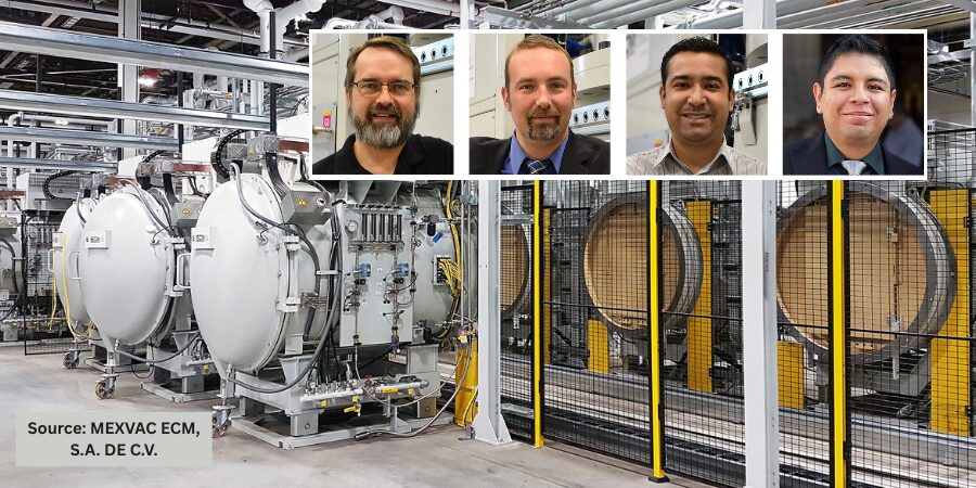
The Mexico heat treatment industry has a new vacuum furnace supplier entity – ECM Mexico, doing business as MEXVAC ECM, S.A. DE C.V., a subsidiary of ECM USA, Inc.

ECM Mexico‘s team is led by Pierre-Loic Rousset, and Dennis Beauchesne, and includes Juan Cruz (operations manager Mexico), and José López (field service & PLC Engineer). They are supported by the entire ECM USA team and are excited to announce this milestone in their continued dedication to expand service support in Mexico.

Press release is available in its original form here.


ECM Mexico Now Operating As MEXVAC ECM, S.A. DE C.V. Read More »

Heat Treat Economic Indicators for April: A Mixed Bag

Heat Treat Today has gathered the four heat treat industry-specific economic indicators for April 2025. While March showed a positive outlook, this month is indicating a change.

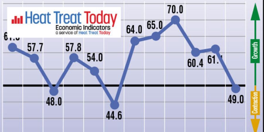
April’s industry-specific economic indicators continued to show growth in two of the four indices while two others have slipped into contraction. Both the Bookings and Backlog indices continue to show growth however at a significantly slower pace compared to March. The Bookings index fell from 58.8 in March to 52.0 this month and the Backlog index fell from 59.3 to 53.3. Any number above 50 indicates growth.

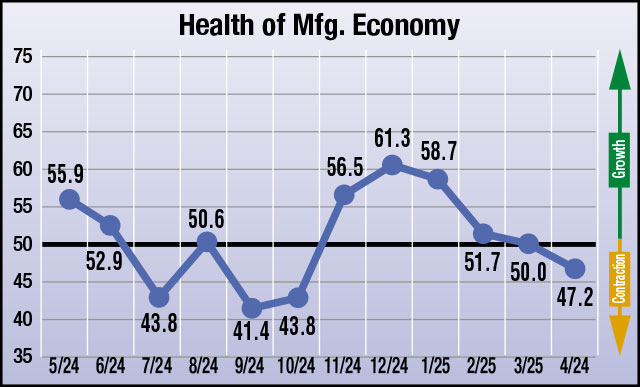
Slipping just below the index number of 50, indicating contraction, were both the Inquiries index and the Health of the Manufacturing Economy index. The former fell from a very strong 61.1 to 49.0, while the later dropped slightly from 50.0 to 47.2.

The graphs suggest that the North American thermal processing industry is experiencing a 4-month slowdown that started in roughly December 2024.

Please note that the above data was collected just prior to tariff announcements by the Trump White House. Next month’s data should show the effect of those tariffs.

The results from this month’s survey (April) are as follows; numbers above 50 indicate growth, numbers below 50 indicate contraction, and the number 50 indicates no change:

  • Anticipated change in Number of Inquiries from March to April: 49.0
  • Anticipated change in Value of Bookings from March to April: 52.0
  • Anticipated change in Size of Backlog from March to April: 53.3
  • Anticipated change in Health of the Manufacturing Economy from March to April: 47.2

Data for April 2025

The four index numbers are reported monthly by Heat Treat Today and made available on the website. 

Heat Treat Today’s Economic Indicators measure and report on four heat treat industry indices. Each month, approximately 800 individuals who classify themselves as suppliers to the North American heat treat industry receive the survey. Above are the results. Data started being collected in June 2023. If you would like to participate in the monthly survey, please click here to subscribe.


Heat Treat Economic Indicators for April: A Mixed Bag Read More »

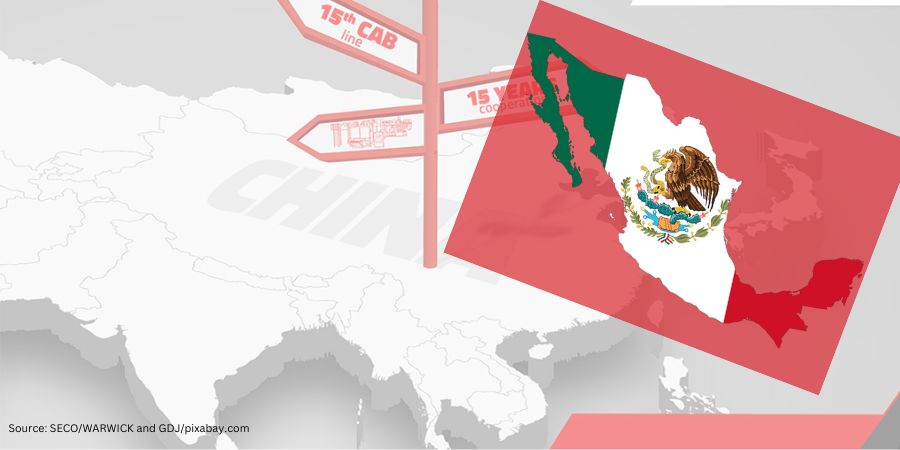
15th CAB Line Ventures to Mexico

After 15 years of collaboration, a new CAB furnace designed for production of heat exchangers for delivery vehicles, trucks, and cars is set to begin operating in Monterrey Mexico.

This 15-year collaboration between SECO/WARWICK and their Asian partner began in 2010 when the two began working together on solutions for heat exchanger production for trucks, passenger cars, and new energy technologies. The new CAB line that will operate in Mexico is equipped with a thermal degreasing furnace, preheating chambers, a radiation furnace, a deicing furnace, a final cooling chamber, and an advanced control system. These features are designed to meet the requirements of the automotive industry, as well as ensure long-term and reliable operation.

Liu Yedong
Managing Director
SECO/WARWICK China.
Piotr Skarbiński
Vice President of Aluminum and CAB Products Segment
SECO/WARWICK

“We can say that this is the jubilee 15th order, exactly on the 15th anniversary of our cooperation beginning,” said Piotr Skarbiński, vice president of the Aluminum and CAB Products Segment at SECO/WARWICK Group.

The CAB line with a 1,400 mm wide belt ensures excellent temperature uniformity across the entire width, which translate into the final product quality,” Liu Yedong, managing director of SECO/WARWICK China added.

Press release is available in its original form here.

15th CAB Line Ventures to Mexico Read More »

Improving Hardening and Introducing Innovation for In-House Heat Treat

In this Technical Tuesday by Paulo Duarte, project manager, Metalsolvus, explores how digital tools lead the way in vacuum hardening operations to ensure energy efficiency and processing repeatability.

This piece was originally published in Heat Treat Today’s March 2025 Aerospace print edition.


Vacuum hardening has been the chosen process for hardening tools used in plastic injection, die casting, and metal sheet stamping over the past few decades. Although widely used and accepted, there is still room for improvement in tool performance through quality-driven procedures. By employing easy methods of measurement, study, and testing, it is possible to enhance part integrity and mechanical properties, while simultaneously reducing heat treatment time and energy consumption. Advanced metallurgical analyses of heat treatment cycles and equipment can introduce better tools on the market, as well as provide time and cost saving heat treatments.

Basics of Vacuum Hardening

In vacuum hardening furnaces, temperature and time are carefully controlled at specific load locations to ensure optimal hardening. Optimal
practices focus on heating and soaking the metal parts during heat treatment. The controlled introduction of vacuum and inert gases during the process ensures the right protective atmosphere for treatment, resulting in steel that is mainly free from oxidation and decarburization. This preserves the surface integrity of the tools.

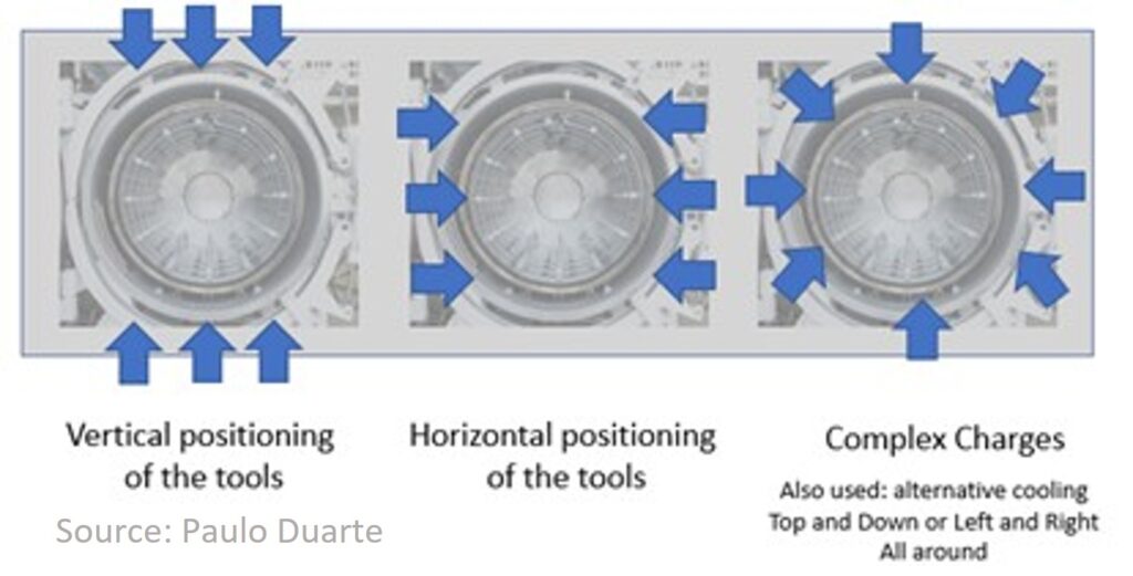
Cooling is achieved through the injection of an inert gas into the heating chamber, with controlled pressure and adequate recirculation between the heat exchanger and the hot zone (Figure 1). Different gas injection directions are utilized depending on the load being treated, ensuring optimal cooling.

Figure 1. Cooling parts in vacuum hardening furnaces — inert gas injection on the hot chamber during cooling

Hardening of Large Tools

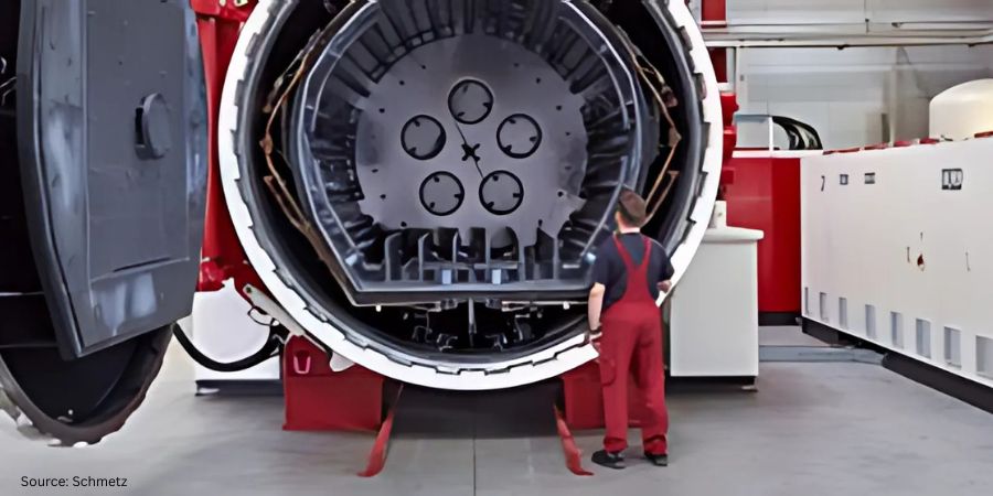
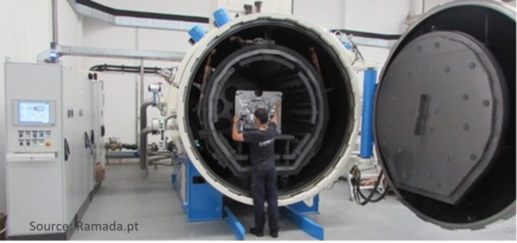
Heating and quenching large tools is one of the most challenging situations for vacuum hardening, as temperature control and part microstructure integrity are more difficult to obtain, which affects part quality. Large tools, typically made of hot work tool steels, are hardened in large furnaces. To minimize deformation, parts are preferably positioned vertically inside the furnace (Figure 2).

Figure 2. Large molds positioned inside the vacuum hardening furnace, two parallel cavities

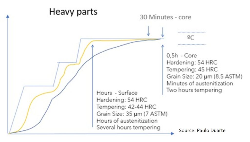
Surface soaking times for big tools can significantly exceed standard austenitization and tempering times due to thermal gradients existing within the
parts. Mold cores usually achieve the right soaking and tempering recommendation through accurate temperature control, monitored by well-positioned core thermocouples. A tool’s microstructure and performance will depend heavily on geometry, size, and temperature uniformity achieved during treatment. See Figure 3 for the core and surface typical hardening cycles for large tools.

Figure 3. Heating and soaking cycle for the hardening of large tools (“Heat Treatment of a AISI H11 Premium Hot-Work Tool Steel”)

The cooling phase is crucial in determining the final properties of both the surface and core of the tool. Higher gas injection pressures result in faster
cooling and increased toughness, but this also introduces greater deformation risks, when directly cooled from austenitization temperature, so martempering done at low pressures is usually required.

Balancing cooling pressure is one of the most secret topics in vacuum hardening. With a variety of parameters and procedures used among heat treaters, measuring and testing is essential for achieving consistent quality for better controlling the hardening process and attaining the best part quality.

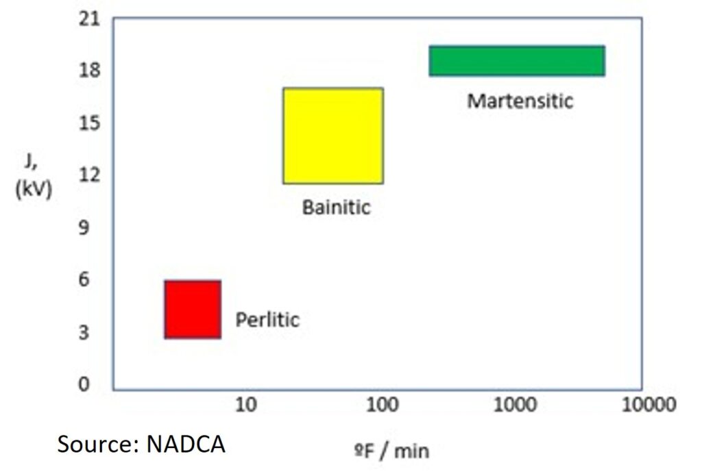
Figure 4. Microstructure and toughness obtained after the use of different hardening cooling rates (image from Transactions of the 15th NADCA Congress, 1989)

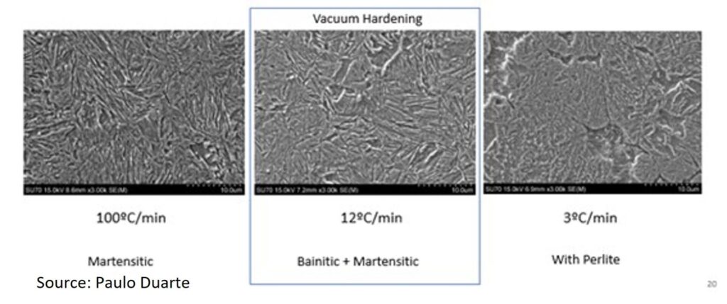
The use of higher or lower inert gas pressures directly affects the cooling rate, making it faster or slower, respectively. Regulating the gas injection pressure during the cooling phase significantly impacts the material’s toughness, even when cooling occurs within the bainitic-martensitic domain commonly observed in vacuum hardening practices. Faster cooling leads to finer microstructures, which in turn results in tougher materials. However, fully martensitic microstructures are rarely achieved in industrial vacuum hardening furnaces and are typically limited to smaller loads composed of
small parts. In larger parts, the risk of pearlite formation increases, especially when cooling rates fall around 3°C/min (5°F/min) at the core, as illustrated in Figures 4 and 5.

Figure 5. Microstructure of Uddeholm Orvar Supreme steel after quenching using different cooling rates

In industrial heat treatments of large tools, accurately monitoring core temperature is challenging, as it is difficult to position a thermocouple hole exactly at the innermost location or a nearby region. This makes it harder to control the hardening process and prevent pearlite formation. Therefore, studying the process to establish effective control measures is essential for achieving the highest possible quality.

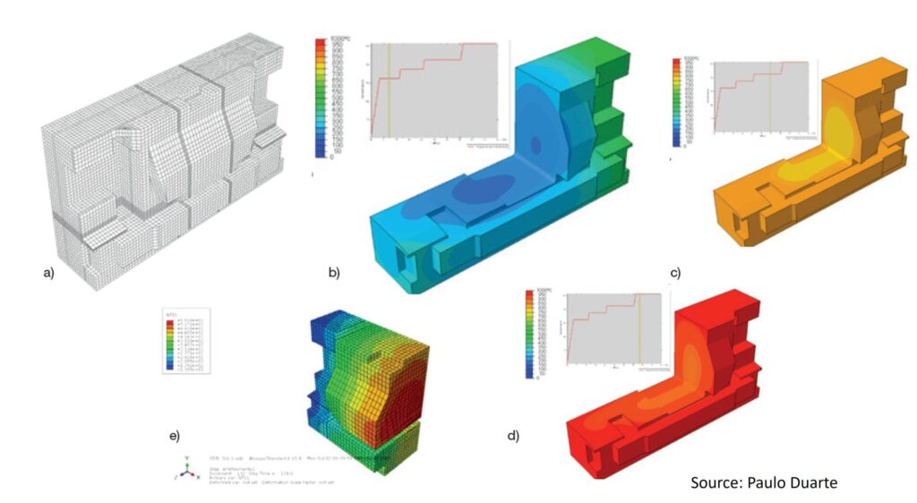
Heat treatment simulation simplifies this task by allowing the hardening process to be predicted, with thermal gradients estimated and compensated through furnace control parameter adjustments. Figure 6 presents a real case study, where the temperature distribution inside a large mold was fully characterized during the entire heat treatment cycle using FEM (Finite element method) simulation and validated through actual thermocouple measurements. FEM simulation, as a proven and highly effective technique for predicting heat treatment cycles, enables heat treaters to implement optimized, computer-supported heat treatment practices.

Figure 6. Mold temperature gradients during vacuum hardening: a) FEM mesh, b) gradients during heating at lower temperatures, c) gradients at the last pre-heating steps, and d) gradients during austenitization from Maia et al. “Study of Heating Stage of Big Dimension Steel Parts Hardening”; e) gradients during mold cooling from Pinho et al. “Modelling and Simulation of Vacuum Hardening of Tool Steels”

Vacuum Hardening Standard Block
Size and Cycle Forecast

When working with loads composed of small to medium-sized parts, the core temperature of the load can be monitored using dummy standard blocks. These blocks have a central hole to accommodate the thermocouple used to control the heat treatment cycle. The dummy block should be selected to
closely match the size of the largest part in the load. However, in commercial heat treatment settings, part sizes can vary widely, making it di cult to maintain a comprehensive set of dummy blocks that represents all possible heat treatment scenarios.

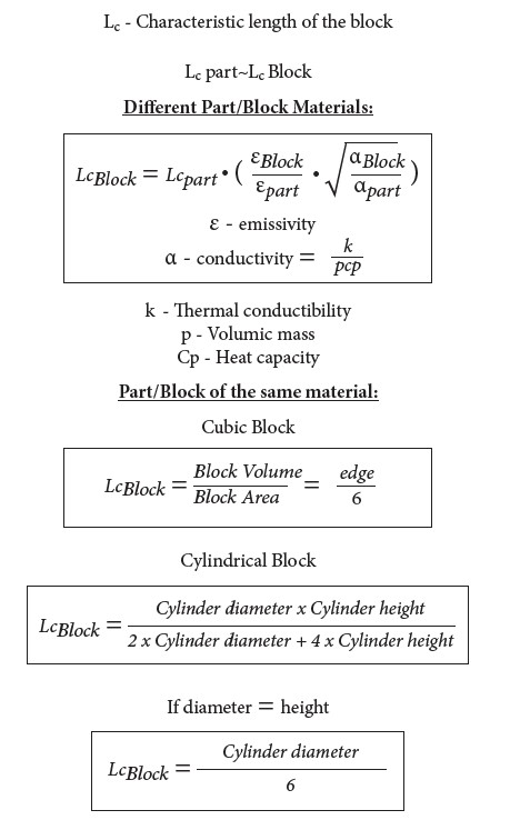
Once again, simulation proves valuable in helping heat treaters gather useful data to anticipate the heat treatment cycle and determine the appropriate range of dummy blocks to have available on the shop floor. The procedure for selecting the dummy block range and forecasting the corresponding
heat treatment times is outlined in the following equations. Ideally, the standard block should be made from the same material as the largest part in the load. If the materials differ, the characteristic length of the block can be calculated using the first of the following equations.

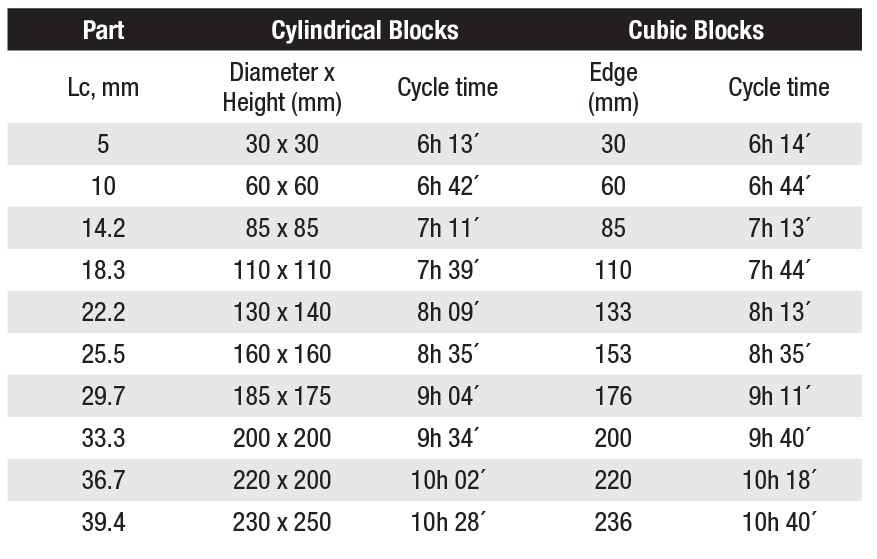
Table 1. Proposed dimensional distribution range for cubic and cylindrical standard blocks and expected cycle times in a typical 600 x 600 x 900 mm hardening furnace (data from Figueiredo et al., “Study of a Methodology for Selecting Standard Blocks for Hardening Heat Treatments”)

Table 1 lists a range of proposed dummy block sizes to be used for monitoring the load temperature during heat treatment. The time to end of soaking at higher temperature is also given by Table 1 for a typical 600 x 600 x 900 mm hardening furnace. Times were obtained by FEM simulation and can be used to forecast the end of austenitization in a hardening process of each dummy block.

The simulated times were validated by using real parts temperature measurement by thermocouples. These were the calculated errors based on simulation and heat treat validation trial:

  • Plate Example: 20 x 300 x 200 mm
  • Ideal standard block: diameter or edge: 51 mm
  • Maximum Error — same material block:
    • Cylindrical: -0.2% (-0.7 min)
    • Cubic: -0.1% (-0.4 min)
  • Maximum Error — block — Stainless steel 304:
    • Cylindrical: +2.2% (+9.2 min)
    • Cubic: +1.65% (+6.9 min)
  • EDM Block Example: 200 x 200 x 200 mm
  • Ideal standard block: diameter or edge: 200 mm
  • Maximum Error — same material block:
    • Cylindrical: -3.9% (-22.6 min)
    • Cubic: 0% (0 min)
  • Maximum Error — block — stainless steel 304:
    • Cylindrical: +17.3% (+100.3 min)
    • Cubic: +12.2% (+70.8 min)

Optimizing the Vacuum Hardening of Tools

Figure 7. Effect of selecting different temperature (T) range for starting to control the isothermal stage time. a) T criteria and respective cycle time reduction; b) surface mechanical properties obtained by using different T; and c) core properties after tempering at different T range (Miranda et al., “Heat Treatment of a AISI H11 Premium Hot-Work Tool Steel,” MSC)

FEM simulation can also be used to optimize the heat treatment process, but metallurgical testing remains crucial for providing reliable insights into safely reducing cycle time and energy consumption. Typically, for setting the isothermal stage time, a tolerance of -5°C relative to the temperature setpoint is used, leading to savings in both heat treatment duration and power consumption, as shown in Figure 7a. However, Figure 7b demonstrates that higher tolerance values (ΔT) can be considered. Tolerances of up to -10°C or even -20°C can be applied for controlling the soaking time without significantly affecting the hardness and toughness of the parts. Naturally, these results depend on the desired setpoints for the isothermal stages, but Figure 7c reflects the worst-case scenario for ΔT, referring to the use of lower austenitizing and tempering temperatures commonly applied in the hardening of hot-work tool steels.

Future Trends of Vacuum Hardening

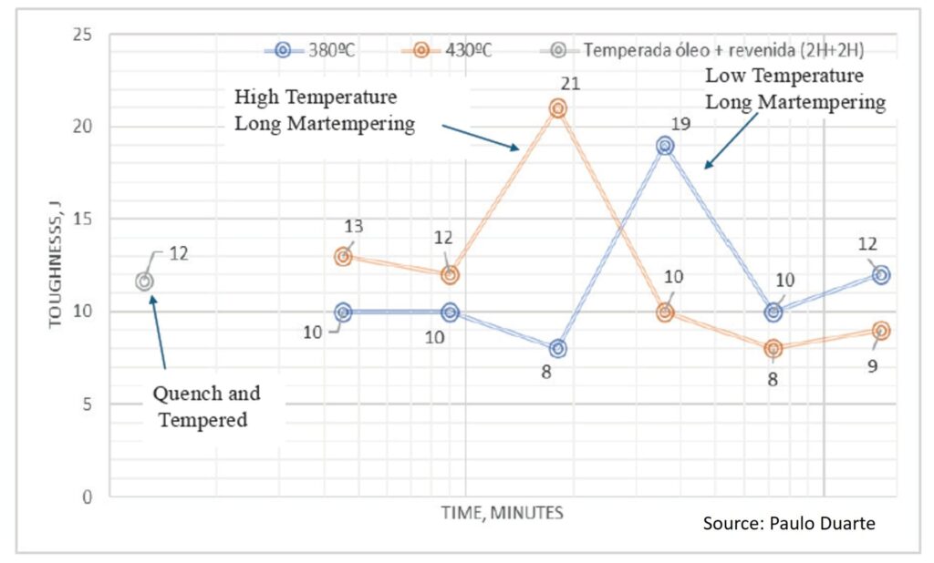
Innovations like digitalization, automation, and resource reduction, as part of Industry 5.0 initiatives, are expected to drive advancements in heat treatment processes. Long martempering, a heat treatment under development for hardening hot-work tool steels, shows promise as an alternative to traditional quenching and tempering. This process offers a balance of high hardness and toughness in significantly less time, providing energy savings and faster turnaround.

Figure 8. New long martempering heat treatment cycle: AISI H13 premium toughness for two different long martempering temperatures (“Study of The Bainitic Transformation of H13 Premium Steel”)

New Vacuum Hardening Process — Long Martempering

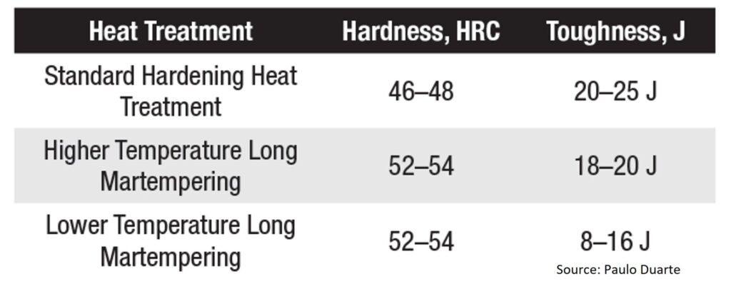
Long martempering is a heat treatment under development that can be used to harden hot-work tool steels. Long martempering is a process somewhat similar to austempering but is applied to steels rather than cast irons. Performed at temperatures within the martempering range, long martempering corresponds to an interrupted bainitic heat treatment with a specific process window (Figure 8) where high toughness is achieved at hardness levels exceeding those obtained through traditional quenching and tempering. Table 2 lists the mechanical properties attained for 5Cr hot-work premium tool steels.

The transformation during long martempering is not yet fully characterized in terms of microstructure, however, curved needles of bainitic ferrite are observed without carbide precipitation. This phenomenon is generally not associated with steel but rather with ausferrite in cast irons. Nonetheless,
it is evident in at least H11 and H13 premium steel grades. This one day martempering treatment could potentially replace the traditional two- to three-day heat treatment cycle for large tools, offering significantly faster lead times and reduced energy consumption. Moreover, the mechanical properties achieved through long martempering are notable, as high levels of both hardness and toughness are obtained simultaneously, as demonstrated in Table 2.

Table 2. Mechanical properties of the new hardening process — long martempering

Industry 5.0

The integration of heat treatment equipment with management software enhances furnace utilization, quality control systems, and maintenance practices. Industry 5.0 can be implemented in heat treatment plants through the connection of databases that collect inputs from furnaces (e.g., temperature, time, pressure, heating elements, and auxiliary equipment performance) and production data (e.g., batch numbers, order details, operator
information, cycle setup, and load weight). This data is analyzed by software to generate valuable insights for plant management, process optimization, predictive maintenance, and quality control.

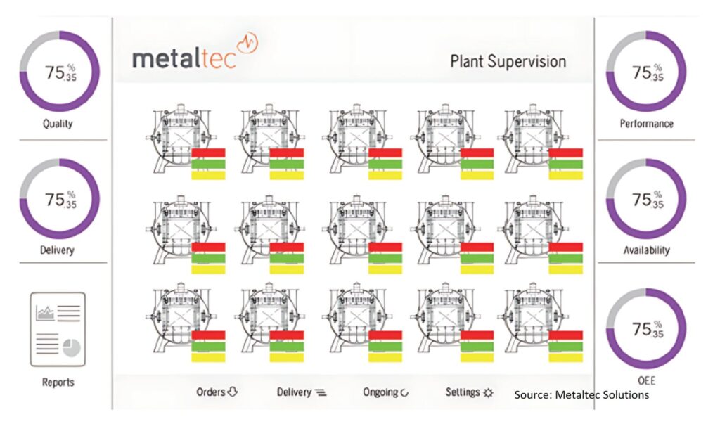
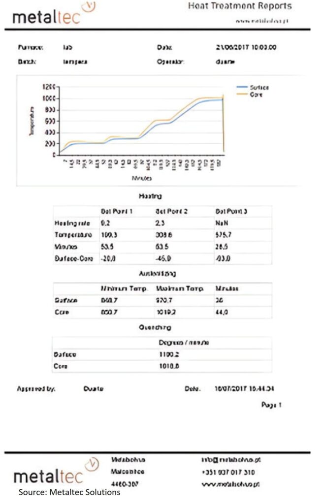
Figure 9. Heat treatment plant supervision solution

A supervision interface for a 5.0 solution can monitor furnaces and control them
remotely in real time (Figure 9). Operators receive updates on tasks, alerts, and production schedules. Additionally, plant productivity, efficiency, and maintenance
can be tracked through the same supervision software, whether on site or remote. Automatic reporting is also possible, enabling the approval or rejection of cycles based on criteria that are not typically used in heat treatment plants. This not only
improves quality but also facilitates process optimization and cost reduction.

Conclusion

Figure 10. Heat treatment quality automatic report including automatic approval

Acquiring a full understanding of furnaces in operation through data measurement and analysis allows full control over the heat treatment process. This facilitates process development, enabling cycle optimization and improvement in part quality. Additionally, testing and simulation practices can lead to cost reduction and shorter lead times.

The introduction of long martempering and Industry 5.0 will significantly enhance heat treatment processes, leading to improved delivery times and reduced operational risks. Automation and digitalization bring more data to the shop floor, improving plant management and resulting in greater efficiency, higher quality parts, and simplified task execution.

Finally, current personnel are busy with routine operations that are based on longestablished practices and may be limiting opportunities for innovation. Therefore, new teams or external consultants can be leveraged to focus on designing, studying, testing, and implementing each new heat treatment solution.

References

Fernandes, José, Laura Ribeiro, and Paulo Duarte. “Study of the Bainitic Transformation of H13 Premium Steel.” MSC thesis, Faculty of Engineering of Oporto University, 2021.

Figueiredo, Ana, Paulo Coelho, José Marafona, and Paulo Duarte. “Study of a Methodology for Selecting Standard Blocks for Hardening Heat Treatments.” MSC thesis, Faculty of Engineering of Oporto University, 2022.

Kind & Co. “Vacuum Hardening with Highest Levels of Precision.” Accessed January 30, 2025. https://www.kind-co.de/en/company/technologies/vacuum-hardening.html.

Maia, Pedro, Paulo Coelho, José Marafona, and Paulo Duarte. “Study of Heating Stage of Big Dimensions Steel Parts Hardening.” MSC thesis, Faculty of Engineering of Oporto University, 2013.

Metaltec Solutions. “Brochure Presentation.” Accessed January 30, 2025. https://www.metalsolvus.pt/en/wp-content/uploads/2019/01/plant-supervisionbrochure-V3.pdf.

Miranda, Isabel, Laura Ribeiro, and Paulo Duarte. “Heat Treatment of AISI H11 Premium Hot-Work Tool Steel.” MSC thesis, Faculty of Engineering of Oporto University, 2024.

Pinho, José Eduardo, Gil Andrade Campos, and Paulo Duarte. “Modelling and Simulation of Vacuum Hardening of Tool Steels.” MSC thesis, Aveiro University, 2017.

Ramada. “New Hardening Furnace up to 4 Tons.” Accessed January 30, 2025. https://www.ramada.pt/pt/media/noticias/novoforno-de-tempera-vacuo—ate-4-tons-.html.

Schmetz. “Schmetz Heat Treatment Furnaces.” Accessed January 30, 2025. https://edelmetal.com.tr/en/heat-treatmentfurnaces.

Schmetz. Sketch of the Cooling Process in the Vacuum Hardening Furnace: Schmetz Commercial Proposals Drawing – Metalsolvus Training Courses
Documentation.

Seco/Warwick. Vector 3D Hardening Furnace Commercial Brochure.

Solar Manufacturing. “Solar Vacuum Hardening Furnace.” Accessed January 30, 2025. https://solarmfg.com/vacuum-furnaces/horizontal-iq-vacuumfurnaces.

Wallace, J.F., W. Roberts, and E. Hakulinen. “Influence of Cooling Rate on the Microstructure and Toughness of Premium Grade H13 Die Steels.” Transactions of the 15th NADCA Congress (1989).

About the Author:

Paulo Duarte is a researcher and consultant on heat treat technologies. His education and expertise in metallurgy has culminated in several articles and patents. He was a former technical manager within bohleruddeholm group for the Portuguese market and heat treatment manager with the same group. Currently, Paulo efforts focus on helping heat treaters by providing innovative, more efficient, and profitable heat treatment services to companies.

For more information: Contact Paulo Duarte at paulo.duarte@metalsolvus.pt.


    Find heat treating products and services when you search On Heat Treat Buyers Guide.com


    Improving Hardening and Introducing Innovation for In-House Heat Treat Read More »

    1 Big Event vs. 7 Industry Events

    Heat Treat Today publishes twelve print magazines a year and included in each is a letter from the editor, Bethany Leone. In this installment, which first appeared in the March 2025 Aerospace Heat Treating print edition, Bethany gives a preview of important events ahead in 2025 for the heat treating industry.

    Feel free to contact Bethany at bethany@heattreattoday.com if you have a question or comment. 


    Just about now, the demands of one big event — welcoming a newborn into our family — will be monopolizing my time for the next few months. While I am more than happy to set aside work to get to know this little person, let’s not deny that I’m missing out on quite a few amazing industry events!

    The late spring period of the year sees more people willing to travel, and so events abound for our industry. This editor’s page highlights just a few things that you can enjoy (and that I will be missing) between now and June.

    March Highlights

    The end of March kicks off the trade show season in Las Vegas, NV. At TMS 2025, metallurgists gather from March 23 to 27 to discuss industrial innovations. With more than 100 symposia on the docket, the sessions are divided into 11 tracks. These categories include additive manufacturing, advanced characterization methods, and light metals. The exhibition includes a poster presentation space. Suffice it to say, this event is intended for heat treat researchers and implementers who are looking to hear about practical innovations in the materials space.

    April Highlights

    Four years ago, I attended the International Conference on Hot Isostatic Pressing (HIP) in Ohio. This April 6 to 10, the city of Aachen, Germany, will be hosting the conference. Attend sessions and tour plants in the area over the course of several days. Additive manufacturing coupled with HIP as well
    as heat treating with HIP vessels will be part of the discussion. The event page says, “Improvements in HIP technology … have the potential to strengthen the competitiveness of many companies which are active in emerging industrial areas.”

    During that same week, heat treaters will be gathering in Detroit, MI, for RAPID + TCT from April 8 to 10. For those interested in staying at the top of industrial innovation in additive manufacturing and industrial 3D printing, this is the event to watch. Browse real-world solutions at the show and dig into the details at technical sessions. Being that this is the largest AM show in North America, it is worth a visit if this is a technology your operations are curious about or interested in understanding better.

    The following week, CastExpo will be attracting suppliers, peers, and customers to the casting market. Happening in Atlanta, GA, from April 12 to 15, this is primarily a time once every three years to network and advance strategy. Among the different topics addressed through exhibits, presentations, and featured events, two are particularly noteworthy for the U.S. manufacturing industry in 2025: reshoring and supply chain & logistics. Of ever-growing importance are topics such as artificial intelligence & machine learning and simulation.

    If you are interested in any part of the ceramics supply chain — be it sourcing material or implementing new technologies, the Ceramics Expo USA in Novi, MI, will be the event to attend from April 28 to 30.  is annual event, like many, offers space to collaborate and new partners to create solutions.

    May Highlights

    Launch your May with AISTech 2025 returning to Nashville, TN. The annual iron and steel conference offers opportunities to connect and hear advances
    happening in the industry. There are so many opportunities to connect with suppliers in the industry and advance one’s understanding of what is happening. From May 5 to 8, you can take the pulse of what direction this segment of American manufacturing is headed and how to prepare.

    Bonus Event

    While nominations are always open, Heat Treat Today’s 40 Under 40 launch will be happening in May 2025. Jayna McGowan led the charge last year,
    and the team already is excited to see what in-house heat treat professionals in North American manufacturing will be nominated and recognized this year. Visit www.heattreattoday.com/40under40 for more information about how to nominate.

    I’m looking forward to reconnecting with the industry folks later this summer. In the meantime, there are a few Heat Treat Kids onesies I’m needing to sort …

    Bethany Leone
    Managing Editor
    Heat Treat Today

    Contact Bethany at bethany@heattreattoday.com.


    Find Heat Treating Products And Services When You Search On Heat Treat Buyers Guide.Com


    1 Big Event vs. 7 Industry Events Read More »
    Major Auto Maker Pledges $20 Billion for US

    A major automaker announced a $20 billion investment in United States-based manufacturing.

    Hyundai‘s investment, which the automaker described as a pledge to increase localized production in the United States, will create over 1,000 jobs. As part of the pledge, the company will open a $5.8 billion steel plant in Louisiana.

    This near-shoring move by Hyundai is one among many automakers who are currently planning major U.S. investments, including Stellantis, which promised $5 billion to U.S manufacturing and Honda, which is expected to produce new Civic hybrids in Indiana.

    Press release is available in its original from here.


    Find heat treating products and services when you search on Heat Treat Buyers Guide.Com


    Major Auto Maker Pledges $20 Billion for US Read More »

    Walk-In Batch Ovens Shipped To Energy Industry

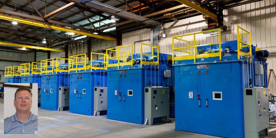
    A shipment of six (6) heavy-duty walk-in batch ovens was delivered to a manufacturer of products for the energy industry. These industrial ovens will be used for baking glue onto products.

    Mark Schahczinski, Senior Sales Engineer, Wisconsin Oven Corporation

    The batch ovens, from Wisconsin Oven Corporation, have a maximum operating temperature of 500°F and guaranteed temperature uniformity of ±5°F at 285°F. A combination airflow configuration ensures even heat distribution throughout the chambers to optimize heating rates and temperature uniformity. Nine (9) point profile tests were conducted in each empty chamber under static operating conditions to verify temperature uniformity. 

    “We are proud to continue our partnership with this valued customer who has purchased multiple ovens from Wisconsin Oven over the years. Their trust in our products is a testament to our commitment to providing high quality equipment and building long term relationships with our customers,” said Mark Schahczinski, Senior Sales Engineer, Wisconsin Oven Corporation.

    Press release is available in its original form here.

    Walk-In Batch Ovens Shipped To Energy Industry Read More »