Thermal Product Solutions (TPS), a global manufacturer of thermal-processing equipment, announced the shipment of a Blue M Ultra-Temp Standard Convection Oven to the Orthodontics industry. The convection oven will be used for a metal injection molding debind process at temperatures of 390°F and 1050°F.
The Blue M oven work chamber is 48” W x 24” D x 36” H and has a maximum temperature rating of 1300°F. The customer’s parts will be placed on ceramic trays then run through the debind cycle that usually lasts 14 to 16-hour cycle. The process off gasses some non-hazardous fumes that condense into a form of wax. The parts are loaded into the oven via a lift truck.
The oven has a powered exhaust with VFD for pulling out non-hazardous fumes coming from the products during the de-binding process. The VFD will enable the customer to adjust the exhaust motor speed to reduce or increase the exhaust flow rate.
Unique features of these Blue M ovens include:
Powered exhaust
Reinforced chamber floor to hold up to 500-lbs distributed load
6-inch high angle iron floor stand to raise the oven and allow customer to insert their lift truck under the oven to load their product into the oven work space
Sapa has developed the first-ever automotive aluminium brake line using a high-strength aluminium alloy.
“The entire industry is on a mission to reduce weight in cars as a key to lowering emissions. In Sapa, we are using our knowledge to identify new parts where we can use aluminium to make cars lighter, safer and more efficient. The brake line development is one such innovation that can reduce the weight with over 50 percent compared to steel,” says innovation and technology manager Jens Sandahl Sørensen.
Fourteen meters of weight savings The normal volume of a brake line in a light vehicle is around 12-14 meters. By replacing steel with aluminium in this component, car manufacturers can shed around 600 grams of the approximately 1 kilogram of weight.
“Aluminium is a material that gives enormous flexibility in both design and workability, and this opens up for new developments. The automotive market is one of Sapa’s main markets, and we are dedicated to investing in research and development to help car manufacturers develop lighter and safer cars,” says business development manager Klaus J. Sandfeld.
The full potential of extruded aluminium in cars and trucks is far from realized. Aluminium is often viewed only as an alternative material, but aluminium is not lightweight steel. “You can design components that simply cannot be manufactured in steel, with different properties and added functionality,” says Sandfeld.
Sapa supplies the automotive industry with a broad range of solutions based on aluminium profiles, from semi-finished to fully fabricated and value-adding components.
Facts about the brake line
– The high-strength alloy in combination with a proprietary designed production process and line-connection design brings optimized mechanical properties toward brake lines requirements.
– The new solution has passed tests toward OEM specifications, including vibration, burst, torque, leak, coating adhesion and corrosion.
Russia’s VSMPO-AVISMA Corporation, the world’s largest titanium producer, is successfully increasing the share of machining in its output both within its own projects and jointly with partners. The company’s close ties with the international aerospace industry allow it to plan further production growth.
Alcoa Samara (Arconic SMZ), Russia’s largest producer of fabricated aluminum and VSMPO-AVISMA Corporation, the world’s largest manufacturer of titanium ingots and forged products, have announced the operational launch of a joint venture.
Read more to find out the name of this joint venture.
Harper International, world leader in custom thermal processing solutions for advanced materials, has been awarded a contract for a high volume Rotary furnace system by Prayon, headquartered in Belgium.
The innovative reactor will be used for drying and calcining of Prayon’s advanced iron phosphate powder, a key component of lithium iron phosphate (LiFePO4) cathode materials used in rechargeable batteries for electric vehicles, and is a part of their recently announced new plant investment to supply the lithium ion battery market. The gas-fired Harper Rotary kiln will support their high volume operations with features to maximize Prayon’s production, including advanced tube features to provide enhanced reaction kinetics, gas-tight and dust-tight design, and internal heat recovery within the furnace chamber to improve energy efficiency. Prayon collaborated with Harper through their Ignite™ process during the development phase by supporting scale up planning and analysis. The Ignite™ program offers scale-up expertise and testing resources to help minimize risk and maximize efficiency for pilot and production level outputs. “Harper is focused on supporting the next generation of materials in advanced markets, and this project for the lithium iron phosphate market is a great representation of that”, commented Brian Fuller, Sales Manager for Harper International. “The material is an ideal solution for many of today’s most progressive technologies for electric power and storage battery systems, and we are proud to be a part of Prayon’s solution to supply this market.”
This is the first time in the world that titanium sheet has been used as fuel tank material for a mass produced motorcycle. Read more to find out the other features of the CRF450R.
EDM is a tried and accepted, economical method of machining many different tool steels. This method of EDM machining can produce very intricate shapes can be machined to very accurate sizes.
However there are problems which can (and do) occur that are associated with the EDM process in relation to the final heat treatment of the die or tool.
It is most important for both the toolmaker and the heat treater to have an understanding of the resulting metallurgy and surface layer construction in relation to the final heat treatment.
Below is shown a schematic of both system principle and the resulting operation of the EDM process.
Figure 1. Schematic of the principle of the EDM procedure. (Courtesy of KMCT College, India)
Figure 2: Schematic of the principle of EDM operation. (Courtesy JD Online, KMCT College India)
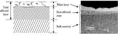
The final EDM layer is generally seen (microscopically) as follows;
The surface layer which is also known as The Recast Layer. This layer is at the immediate surface and is generally very hard and brittle. (Remember it has seen a very high temperature, which is up to the point of melting). The objective of the EDM is to vaporize the surface layer and remove it. But it is, in reality a melted layer which will cool rapidly at the surface of the tool. The surface is now in a highly residual and stress full condition which can and very often does, lead to cracking, heat checking and ultimately premature surface failure. More often than not, it is the heat treater who is blamed, no matter how careful the heat treater has treated the tool.
Figure 3: Characteristic layers of a subsurface.
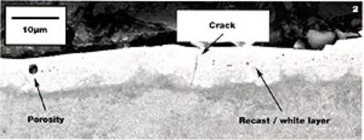
Figure 4: The recast layer is a layer of untempered martensite with a high crack risk potential.
The untempered martensite transformation occurs due to the heat sink that takes place from the generated heat of the EDM. The generated heat energy diffuses into the body of the tool and creates the appropriate transformation from austenite into martensite because of the rate of cooling. This will give rise to a stressful potential crack occurrence condition (due to the untempered, unstable m fresh martensite). Hardness values of the untempered martensite layer can be as high as 62 HRC (depending of course on the chemistry of the steel).
Figure 5: Illustration of the cracked untempered martensite after EDM.
Below the untempered martensite layer will be another layer of what can be a tempered martensite layer with hardness values (once again depending on the steel chemistry) in the region of up to 52 to 54HRC.
Below that layer on tempered martensite will be the original hardness and microstructure of the base material.
The recast layer is the dangerous layer, because not all of the melted layer has been flushed away. When a failed/cracked sample is etched, the recast layer will be seen as a white layer (do not confuse with the white layer of a nitrided surface).
What can be done to prevent (or at least reduce the risk of potential cracking)? The only simple procedure (but with no guarantee) that can reduce the risk of cracking, would be to temper the component immediately after the EDM procedure.
A Tier 1 automotive supplier located in the Midwest has placed (2) orders with AFC-Holcroft for the supply of heat treating equipment related to the processing of aluminum.
The first order will consist of a Roller Hearth Homogenizing Furnace for processing aluminum products. The complete system includes a multi-position loading table, a multi-position furnace, cooling station and multi-position unload table.
The second order is for a Solution Heat Treat Line, which will also be used for processing aluminum products. This system will include charge and discharge transfer cars, a multi-position solution furnace, water quench system, multi-position age furnace, multi-position accumulation charge and discharge tables, accumulation cross-over mechanism and a tray pull-off station.
Additionally, AFC-Holcroft will provide their Remote Diagnostic Service™ during the furnace warranty period. This service provides a complete remote monitoring and diagnostic package including transmission and analysis of machine data, targeting the most common or noteworthy events and identifying root causes. The Remote Diagnostic Service transmits data automatically to AFC-Holcroft’s secure servers, eliminating the human time and cost associated with manually gathering historical data for the same purpose.
“While AFC-Holcroft is best known for providing equipment for the processing of steel components, we also have a long history of providing equipment to the aluminum industry” stated Mark Johnston, Aftermarket Equipment Sales. “This order is a further inroad into this growing market.”
Sapa Extrusions opened a new R&D lab in Troy, MI, dedicated to the development of extruded aluminum solutions for the automotive industry. Read more to find out what key disciplines will be available at Sapa Technology Americas.
This is the second in a series of articles by AMS 2750 expert, Jason Schulze. Don't miss the Q&A section at the bottom of this article and please submit your AMS 2750 questions for Jason to Doug@HeatTreatToday.com.
Introduction
Considering the abundant number of Nadcap heat treat audits performed in a single year, the area receiving the most findings is pyrometry, and within this group, system accuracy testing (SAT) is the third most common finding.
The SAT process has been refined through each revision of AMS2750 (C through E). We’ve seen SAT thermocouple requirements, for example, gradually incorporated into the tables but not within the body of the specification. Also, we’ve seen the definition of a SAT incorporated into revision D within the definitions section; however, with revision E it was added to the body of the specification.
AMS2750E presents three optional methods for performance of SATs that must be implemented; the Standard (or Regular) SAT, the Alternate SAT, and the SAT Waiver. Within this article, we will focus on the Standard SAT process.
Standard SAT Description – AMS 2750E
AMS2750E has defined the Standard SAT as:
An on-site comparison of the instrument/leadwire/sensor readings or values, with the readings or values of a calibrated test instrument/leadwire/sensor to determine if the measured temperature deviations are within applicable requirements. Performed to assure the accuracy of the furnace control and recorder system in each control zone.
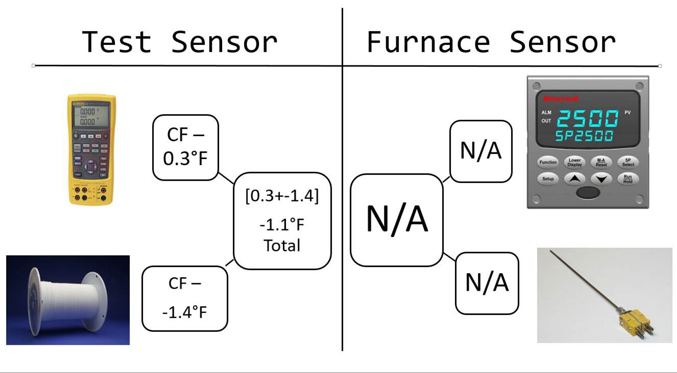
Put simply, an SAT is a comparison of two systems: the furnace system (whether control, monitoring, or load) against a test system. It’s important to recognize that the comparison is being made against two systems and not against an instrument or thermocouple alone. Each system is made up of three variables:
the instrument
the lead wire
the sensor
SAT Procedure
There is no general SAT procedure that can be applied for every supplier. Each supplier has their own needs as well as their own mechanical arrangement of thermocouples within their furnace system. The key to conformity is to ensure that, once a method for performing an SAT on a furnace is established, it is documented (i.e., in detail, including photos, if necessary) and repeated each time an SAT is performed. Some requirements to incorporate into your system are:
1) The tip-to-tip distance between the furnace system thermocouple and the test system thermocouple cannot exceed 3 inches.
2) The test thermocouple shall be in the same position/depth as the initial test.
3) The furnace is cycled and maintained at a temperature normally used during production.
4) Each system that makes up the applicable instrumentation type must be tested.
SAT Difference
Many findings arise from suppliers calculating the SAT Difference incorrectly. AMS 2750E states the following as a way to calculate the SAT Difference.
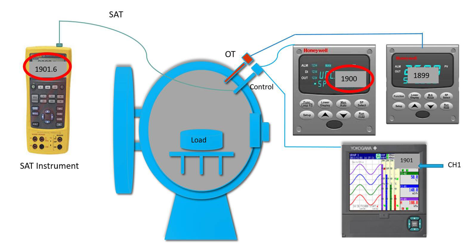
The difference calculated between the reading of the furnace sensor system being tested (sensor, lead wire, and instrument) and the corrected reading of the test sensor system (after test sensor and test instrument correction factors are applied) shall be recorded as the system accuracy test difference. Applicable correction factors shall be applied algebraically.
I’ve highlighted the word “corrected” as it applies to the test instrument systems because this seems to be a source of frequent findings. The furnace system does not get corrected, the test system does get corrected.
As an example, let’s consider a vacuum furnace which has had an SAT performed. The vacuum furnace is designated a Class 3 (±15°F) Type D furnace. Let’s assume no additional furnace thermocouples are employed and we are performing an SAT on the control and recording systems. The readings obtained are below in the picture.
*The example above is not an SAT Certification. It’s an example of how to calculate the SAT Difference in a given situation.
Conclusion
SATs can be difficult depending on the equipment and processes suppliers have. As always, it’s important to receive comprehensive training regarding the specific requirements of System Accuracy Testing as they apply to your facility. There are many particular aspects of SATs that may not have been accounted for in this article. If you have specific questions, please email them to doug@heattreattoday.com, and I will answer them in an upcoming article.
Submit Your Questions
Please feel free to submit your questions, and I will answer appropriately in future articles.
Out next topic will focus on the requirements and execution of an Alternate SAT per AMS2750E, the requirements of AC7102/8 and the Pyrometry Guide.
Q/A with Jason Schulz
Q: When calculating the SAT Difference, should I include the correction factors of the furnace sensor?
A: No, the correction factor from the furnace sensor is not to be included in the SAT Difference calculation.
Q: How do I account for an internal (pre-programmed) TUS offset within the controller when calculating the SAT Difference?
A: Internal or electronic TUS offset must be algebraically removed when calculating the SAT Difference. Below is an example that includes an electronic TUS offset of -2°F.
Q: I operate a furnace with 2 load sensors. One of them is used to signal the start and end of each soak cycle, the other is reference only. Do I have to perform an SAT on the load thermocouple I use as a reference only thermocouple?
A: Any thermocouple that is not used as product acceptance may be deemed reference only and is not subject to the SAT requirements of AMS2750E. Nadcap requires that the reference only thermocouples be accounted for in internal procedures.
Q: When performing my bi-weekly SAT, I get a difference of +2.6°F on one test and two weeks later I get a difference of -3°F; this constitutes a spread (within two weeks) of 5.6°F. Would this be cause for SAT failure?
A: According to AMS2750E and Nadcap, no, this would not constitute a failed SAT, though is something to be cautious of. This type of shift in SAT results does reflect some sort of change or degradation of the system being tested. A well-established tack, in this case, is to plot SAT results as part of an SPC (statistical process control) program which will govern future replacement of system thermocouples and/or leadwire (in the case when large difference is SAT results over a pre-determined amount). A documented SPC system for SAT results would also satisfy the requirements of AC7102/8(NA) page 2, paragraph 3.12.