MANUFACTURING HEAT TREAT NEWS

DC53 “Only as Good as the Heat Treatment It Receives”

.
Source: International Mold Steel, Inc.

.

DC53 Steel, a general purpose cold work mold and die steel with exceptional strength and resistance qualities, is nonetheless “only as good as the heat treatment it receives,” according to our Best of the Web resource today. Not surprisingly, manufacturers find these excellent characteristics for machining applications.

The folks at International Mold Steel, Inc., a steel distributor in Florence, Kentucky, have compiled a primer on heat treating DC53, which is known not only for its strength and resistance, as mentioned, but also for have a higher hardness than D2 after heat treatment. This is critical for machining shops where die and mold life expectancy is dependent upon proper high-temperature tempering and high hardness.

Read more: “DC53 Heat Treat”


DC53 “Only as Good as the Heat Treatment It Receives” Read More »

Heat Treatment of FDM Parts to Determine Effect on 3D Printing: UT-Arlington Study


Source: 3DPrint.com


A University of Texas at Arlington thesis student recently investigated thermal annealing to determine how to increase inter-bead bond strength overall in 3D printing processes.

Rhugdhrivya Rane tackled the dilemma of weak tensile strength in FDM parts and whether parameters chosen by the user — such as temperature ranges and pressure gradients — can affect an increase in inter-bead bond strength. The researcher used thermal annealing, and thermal annealing with unidirectional mechanical pressure in the Z direction, 3D printing a variety of specimens in ABS. The method of 3D printing was chosen due to its increased popularity in mainstream manufacturing.

“The parts were printed using two different sets of print parameters: high and low settings, to investigate the effect of heat treatment on both sets of print parameters. The values of temperature, time and applied pressure during heat treatment were varied to obtain a detailed comparative study and the correlation between the given variables and the increase in ultimate tensile strength.” ~ Rane

The discovery was that “higher temperatures and longer exposure to heat produced better tensile strength, along with increased ductility.”

“Though thermal annealing and uniaxial pressure cause an increase in the strength of the parts, the print parameters play a vital role in determining the initial mechanical properties of the parts. When the parts are fabricated with a higher value of flow rate and extrusion temperature, they exhibit significantly higher mechanical properties as compared to parts printed with substandard setting,” concluded the researchers. “Thus, by controlling the print parameters and using the right values of temperature and pressure we can see substantial increase in strength of FDM parts.”


Photo credit/caption: via UTA / “Tensile testing of dogbone specimens”

Heat Treatment of FDM Parts to Determine Effect on 3D Printing: UT-Arlington Study Read More »

Heat Treat Tips: Safety and Cost-Saving Hacks

During the day-to-day operation of heat treat departments, many habits are formed and procedures followed that sometimes are done simply because that’s the way they’ve always been done. One of the great benefits of having a community of heat treaters is to challenge those habits and look at new ways of doing things. Heat Treat Today‘101 Heat Treat Tips, tips and tricks that come from some of the industry’s foremost experts, were initially published in the FNA 2018 Special Print Edition, as a way to make the benefits of that community available to as many people as possible. This special edition is available in a digital format here.

Today we continue an intermittent series of posts drawn from the 101 tips. The tips for this post come from a variety of categories but all generally address safety or cost-saving ideas. 


Dr. Valery Rudnev, FASM, Fellow of IFHTSE, Professor Induction, Director Science & Technology, Inductoheat Inc., An Inductotherm Group company

Heat Treat Tip #2

Avoid axle shaft cracks after induction tempering

Situation: In induction scan hardening of axle shafts, there was NO cracking occurred after scan hardening (case depth varies from 5 mm to 8 mm). Cracks appeared in the spline region after induction tempering.
Solution: Most likely, the cause of this problem is associated with a reversal of residual stress distribution during induction tempering. Reduce coil power for tempering and increase time of induction tempering. Multi-pulse induction tempering applying lower power density might also help. As an alternative, instead of modifying temper cycle, you can also try to reduce quench severity by increasing the temperature of the quenchant and/or its concentration.

Submitted by Dr. Valery Rudnev, FASM, Fellow of IFHTSE, Professor Induction, Director Science & Technology, Inductoheat Inc., An Inductotherm Group company


Heat Treat Tip #4

Closed Loop Water System on Top

When designing a vacuum furnace installation with a closed loop water system, elevate the tank and pump about 9 feet, then cage the space underneath for thermocouple storage, spares, and tools. Saves shop floor space.

Submitted by AeroSPC


IR Cameras are inexpensive and worth the price.

Heat Treat Tip #6

Don’t Be Cheap. Buy an IR Camera.

IR cameras have come way down in price—for a thousand dollars, you can have x-ray vision and see furnace insulation problems before they cause major problems—also a great diagnostic tool for motors, circuit breakers, etc. (And you can spot deer in the dark!)

Submitted by Combustion Innovations


Heat Treat Tip #7

An Engineer’s Design Checklist

Get an SCR design checklist and avoid mistakes.

When SCRs are involved in the design of a new piece of equipment, questions arise. Control Concepts Inc of Chanhassen, MN, offers a 20-point design checklist to help engineers who don’t specialize in power controllers. Good reading. Search for “design checklist” at the website.

Submitted by Control Concepts, Inc.


Heat Treat Tip #9

Question the Spec! Save Money!

Before you specify a heat treatment, stop and consider your options. Rather than reusing an old specification, ask the design engineer to determine the stress profile, and base the hardness or case depth on real stress data. Is this complicated? Maybe. But especially for carburizing, why pay for more depth than you need, and why take the risk of inadequate strength? The 21st century is here. We have ways to help with the math. Let’s move beyond guess and test engineering methodology.

Submitted by Debbie Aliya


Heat Treat Tips: Safety and Cost-Saving Hacks Read More »

Heat Treated Steel to be Produced at Ohio River Plate Mill

A steel manufacturer recently announced that it will build its new state of the art steel plate mill in Brandenburg, Kentucky, producing cut-to-length, coiled, heat-treated, and discrete plate.

Nucor Corporation will invest approximately $1.35 billion to build the mill along the Ohio River southwest of Louisville, which will be capable of producing 1.2 million tons per year of steel plate products and is expected to be fully operational in 2022, pending permit and regulatory approvals.

John Ferriola, Chairman, CEO & President of Nucor Corporation

“This strategic investment will enable us to build a clear market leadership position in the U.S. plate market. Kentucky is an excellent location for this mill, right in the center of America’s largest plate consuming region,” said John Ferriola, Chairman, CEO & President of Nucor Corporation. “Our acquisition of the Gallatin sheet mill in Ghent, Kentucky five years ago has been a tremendous success, and we are pleased to add a second mill in the state.”

The new plate mill will give Nucor the ability to produce 97 percent of the products demanded in the domestic plate market, including the specialty higher-margin products, including the discrete plate ranging from 60 to 160 inches wide, and in gauges from 3/16 of an inch to 14 inches. The selected location on the Ohio River will give Nucor logistical advantages in sourcing raw materials and serving customers throughout the Midwest. Nucor currently operates plate mills in North Carolina, Alabama, and Texas.

Nucor has two additional major investment projects underway at its Gallatin sheet mill in Kentucky. Nucor Steel Gallatin’s new galvanizing line will be operational during the second quarter of this year. And, its project to increase Gallatin’s hot-rolled coil capacity at expanded widths of up to 73 inches is expected to come online during 2021. The new plate mill and the projects at Nucor Steel Gallatin represent more than $2 billion in investments in the state of Kentucky.


Heat Treated Steel to be Produced at Ohio River Plate Mill Read More »

Dr. Valery Rudnev on . . . Equipment Selection for Induction Hardening: Continuous and Progressive Hardening, Part 2

This article continues the ongoing discussion on Equipment Selection for Induction Hardening by Dr. Valery Rudnev, FASM, IFHTSE Fellow. Dr. Rudnev previously reviewed equipment selection for scan hardening in three parts. The first part on equipment selection for continuous and progressive hardening is here; the third part is here. To see the earlier articles in the Induction Hardening series at Heat Treat Today as well as other news about Dr. Rudnev, click here


Frequency Selection

Depending on the application specifics, continuous and progressive hardening lines may use the same frequency for various in-line coils. In other cases, power levels and frequencies may be different at different heating positions. The presence of three general process stages (described in Part 1) makes a marked impact on a selection of process parameters and the design of an induction system.

When using different frequencies for the various heating stages, the coil design may need to change as well (e.g., a number of coil turns may need to be adjusted for load matching purpose). Just as the eddy current penetration depth in the heated part is affected by the frequency, the current flow in the inductor is affected as well. The wall thickness of the inductor turns (i.e., copper tubing wall) might need to be adjusted to accommodate different frequencies to maximize the coil electrical efficiency.¹

The wall thickness of an inductor’s heating face should be increased as frequency decreases. It is highly desirable for the current-carrying copper wall thickness to be 1.6 times greater than the current penetration depth in the copper (δCu). Increased kilowatt losses in the copper, which are associated with reduced electrical efficiency and greater water-cooling requirements, will occur if the wall is thinner than 1.6∙δCu. In some cases, the copper wall thickness can be noticeably thicker than the recommended value of 1.6∙δCu. This is because it may be mechanically impractical to use a tubing wall thickness of, for example, 0.25 mm (0.01 in.).

As an example, Figure 1 shows a number of continuous in-line multi-coil systems for induction heat treating wire products.²

Several continuous in-line systems for heat treating wire products (Courtesy of Radyne Corp., and Inductotherm Heating & Welding, UK. Both are Inductotherm Group companies.)

There are noticeable benefits of compact induction systems compared to fluidized beds, infrared heaters, and gas furnaces, such as quick response and the ability to provide a rapid change in the process operating parameters to accommodate the required temperature of the wire/cable being processed at speeds up to 5 mps. Frequencies that are in the range of 10 to 800 kHz are commonly applied. A dual-frequency concept can be beneficial to enhance electrical efficiency of while heating different diameters/thicknesses or it can be advantageous for through heating of metallic alloys that exhibit low toughness/high brittleness.

According to the dual-frequency concept, a lower frequency is used during the initial heating stage when the steel is magnetic. In the final heating stage, when the steel becomes nonmagnetic with significantly increased current penetration depth δsteel and becomes substantially more ductile, it is beneficial to use a higher frequency.

Case study¹:

As an example, consider the induction heating of a 1/8 inch-diameter (3.2 mm-diameter) steel rod from ambient to 2000°F (1100°C) using both a single 10-kHz frequency and dual 10-kHz/200-kHz frequencies (see Figure 2). When using the single frequency of 10 kHz (Figure 2, left), the rod’s final temperature experiences very little change regardless of the coil power that is increased more than fivefold (from 17 to 90 kW). The only noticeable difference is related to the initial slope of the temperature-time curve, where the steel is ferromagnetic. Upon reaching the Curie point, there is no noticeable temperature rise. This is the result of severe eddy current cancellation making the steel rod transparent (practically speaking) to the electromagnetic field of the induction coil.

Illustration of the dual-frequency concept when induction heating a 1/8 inch-diameter (3.2 mm-diameter) carbon steel rod from room temperature to 2012°F (1100°C) using both a single frequency of 10 kHz (a) and dual frequencies of 10 kHz/200 kHz (b). (Source: V.Rudnev, Systematic analysis of induction coil failures, Part 11c: Frequency selection, Heat Treating Progress, January/February, ASM Intl., 2008, pp. 27–29.)

In contrast, Figure 2, right, shows that a dual-frequency approach provides a remarkable improvement in the ability to heat the rod above the Curie temperature. A power of 14 kW/10 kHz was used to heat the rod below the Curie point and a power of 19 kW/200 kHz was used above it. The total required power is only 33 kW, compared with 90 kW using just 10 kHz, which was still unable to provide the required temperature rise.

Note: The target temperature of 2000°F (1100°C) is above typical target temperatures when hardening plain carbon or low alloy steels and it is more suitable for hot forming applications. This temperature was selected here to better illustrate a dual-frequency concept and the importance of avoiding eddy current cancellation when choosing operating electrical frequencies. It should be noted though that it is not unusual that the heat treating protocols/recipes for some alloyed steels and stainless steels may require target temperatures of 1900°F to 2100°F (1050°C to 1150°C) range.

In some not too often cases, three frequencies may be used. Lower frequency is applied for preheating inductors, a medium frequency is used for mid-heat inductors, and a high frequency is used for final heat inductors.

Sometimes, it is required that the induction system should be able to heat a variety of sizes using a single frequency. In these cases, in order to provide efficient steel heating, it is necessary to choose a frequency that will guarantee that the “diameter-to-current penetration depth (δsteel)” ratio exceeds 3.6 for any workpiece diameter or heating stage. Thus, it is important to remember that when calculating δsteel, the values of electrical resistivity and relative magnetic permeability of the heated material should correspond to their values at the highest temperature that occurs during the entire heating cycle.

The next installment of this column will review a variety of styles of inductors used in continuous and progressive induction hardening applications.


References

  1. V.Rudnev, D.Loveless, R.Cook, Handbook of Induction Heating, 2nd Edition, CRC Press, 2017.
  2. J.Mortimer, V.Rudnev, D.Clowes, B.Shaw, “Intricacies of Induction Heating of Wires, Rods, Ropes, and Cables”, Wire Forming, Winter, 2019, p.46-50

Dr. Valery Rudnev, FASM, IFHTSE Fellow, is the Director of Science & Technology, Inductoheat Inc., and a co-author of Handbook of Induction Heating (2nd ed.), along with Don Loveless and Raymond L. Cook. The Handbook of Induction Heating, 2nd ed., is published by CRC Press. For more information click here.

Dr. Valery Rudnev on . . . Equipment Selection for Induction Hardening: Continuous and Progressive Hardening, Part 2 Read More »

Heat Treat Line Expanded at Ontario Facility

A family-owned commercial heat treating company recently expanded the capabilities of its Ontario-based facility with the purchase of two batch furnaces.

Cambridge Heat Treating, located in Cambridge, Ontario, purchased two new Allcase® Batch Integral Quench Furnaces in addition to two used Allcase furnaces to be used in the same line, along with a previously purchased 30”x30”x48” Allcase with top cool.

Surface Combustion, headquartered in Maumee, Ohio, commissioned the new furnaces. which are all serviced by Surface’s charge car, Uni-DRAW® Batch Tempering Furnaces, washers, and RX® Endothermic Atmosphere Gas Generator.  The 36”x48”x36” batch heat treat line expands Cambridge’s capacity for carbonitriding, carburizing, neutral hardening, and has added ferritic nitrocarburizing (FNC) and normalizing capacity with the atmosphere top cool chambers on the two new Allcases.

“We could not be happier with our Surface purchases,” said Peter Robbins, owner of Cambridge Heat Treating. “Their robust equipment is built for longevity, and we appreciate that they are easy to operate and maintain. Surface’s Aftermarket parts department ensures that we always have the necessary parts for maintenance in a timely manner, and their customer service department is always available for a telephone or service call.”


Heat Treat Line Expanded at Ontario Facility Read More »

Heat Treat Control Panel: Best Practices in Digital Data Collection, Storage, Validation

When processing critical components, heat treaters value and demand precision in every step of the process — from the recipe to data collection — for the sake of accurate performance of the furnace, life expectancy of all equipment, as well as satisfactory delivery of a reliable part for the customer.

So what’s the obstacle to achieving those goals? Gunther Braus of dibalog GmbH/dibalog USA Inc. says, “The general problem is the human.” Indeed, the need to remove the variable of human fallibility plays a significant role in the search and development of equipment that could sense, read, and record data separate from any input from the operator. “As long there is a manual record of values there is the potential failure,” adds Braus.

Now, as part of the quest for precision, particularly in the automotive and aerospace industries, many control system requirements are driven by the need to prove process compliance to specified industry standards like CQI-9 and AMS 2750. These standards allow for and frequently require digital data records and digital proof of instrumentation precision.

With this in mind, Heat Treat Today asked six heat treat industry experts a controls-related question. Heat Treat Control Panel will be a periodic feature so if you have a control-related question you’d like addressed, please email it to Editor@HeatTreatToday.com and we’ll put your question to our control panel.

Q: As a heat treat industry control expert, what do you see as some of the best practices when it comes to digital data collection and storage and/or validation of instrumentation precision?

We thank those who responded: Andrew Bassett of Aerospace Testing & Pyrometry, Inc.; Gunther Braus, dibalog GmbH/dibalog USA Inc; Jim Oakes of Super Systems, Inc; Jason Schulze, Conrad Kascik Instrument Systems, Inc.; Peter Sherwin, Eurotherm by Schneider Electric; and Nathan Wright of C3Data.

Calibration and Collection

Jim Oakes (Super Systems Inc.) starts us off with an overview of the equipment review process, the crucial component of instrument calibration, and digital data collection:

“Industry best practices are driven by standards defined by the company and customers they serve. Both the automotive and aerospace industries have a set of standards which are driven through self-assessments and periodic audits. Instrument precision is defined by the equipment’s use and is required to be checked during calibrations. The frequency of these calibration depends on the instrument and what kind of parts and processes it is responsible for.

The equipment used for these processes can be defined as field test instrumentation, controllers, and recording equipment. Calibration is required with a NIST-traceable instrument that has specific accuracy and error requirements. Before- and post-calibration readings are required (commonly identified as “as found” and “as left” recordings). During calibration, a sensitivity check is required on equipment and is recorded as pass/fail. The periodic calibration procedure is carried out not only on test equipment but also on control and recording equipment, to ensure instrument precision.

Digital data collection is a broad term with many approaches in heat treatment. As mentioned, requirements are driven by industry standards such as CQI-9 and AMS 2750. Specifically when it comes to digital data collection, electronic data must be validated for precision; checked; and calibrated periodically as defined by internal procedures or customer standards. Data must be protected from alteration, and have specific accuracy and precision. Best practice tends to be plant wide systems that cover the electronic datalogging that promotes ease of access to current and historical data allowing use for quality, operational, and maintenance personnel. Best practices in many cases are defined by the standards within each company, but the hard requirements are often the AMS 2750 and CQI-9 requirements for digital data storage.”

Industry Guidelines and Requirements

Andrew Bassett (Aerospace Testing & Pyrometry) has provided us with a reminder of the industry guidelines for aerospace manufacturing (via AMS-2750E, paragraph 3.2.7.1 – 3.2.7.1.5)

  1. The system must create electronic records that cannot be altered without detection.
  2. The system software and playback utilities shall provide a means of examining and/or compiling the record data, but shall not provide any means for altering the source data.
  3. The system shall provide the ability to generate accurate and complete copies of records in both human readable and electronic form suitable for inspection, review, and copying.
  4. The system shall be capable of providing evidence the record was reviewed – such as by recording an electronic review, or a method of printing the record for a physical marking indicating review.
  5. The system shall support protection, retention, and retrieval of accurate records throughout the record retention period. Ensure that the hardware and or software shall operate throughout the retention period as specified in paragraph 3.7.
  6. The system shall provide methods (e.g., passwords) to limit system access to only individuals whose authorization is documented.

“One of the biggest issues I see with one of these requirements will be point 5,” says Bassett. “The requirement is to be able to review these records throughout the retention period, which in some instances is indefinite. I always recommend to clients who may be upgrading or purchasing new digital systems that they should consider keeping a spare system in place to be able to satisfy this requirement. Who knows — today we are working on Windows 10, but in 50 years, will our successor be able to go back and review heat treat data when everything is run on Windows 28?”

Jason Schulze, Aerospace Heat Treating“This is a topic that yields great discussions,” adds Jason Schulze (Conrad Kascik). He directs us to a challenge he sees from time to time.

Within the Nadcap AC7102/8 checklist, there is this question: “Do recorder printing and chart speeds meet the requirements of AMS 2750E Table 5 or more stringent customer requirements?” This correlates with AMS2750E, page 12, paragraph 3.2.1.1.2 “Process Recorder Print and Chart Speeds shall be in accordance with Table 5”.

“To ensure the proper use of an electronic data acquisition unit used on furnaces and ovens, these requirements must be understood,” continues Schulze. “Because this system is electronic, it should be designated a digital instrument and not an analog instrument. In doing so, this helps determine what requirements apply in Table 5. The only remaining requirement in Table 5 for digital instruments is ‘Print intervals shall be a minimum of 6 times during each time at temperature cycle. Print intervals shall not exceed 15 minutes.’

With this in mind, it is important to realize that, if your time at temperature cycles are short cycles (such as vacuum braze cycles), the sample rate of data collection may need to be adjusted to ensure it is recorded 6 times during the cycle.

As an example, if the shortest cycle processed is 4 minutes at temperature, a sample rate of every 60 seconds would not conform to AMS2750E because, in theory, the maximum amount of recordings would be 4 times during the time at soak. Now, if the sample rate was modified to every 30 seconds, this would allow ~8 recordings during the time at soak, which then would be conforming to AMS2750E.

Within the realm of electronic data acquisition on furnaces/ovens, this seems to be a frequent challenge for suppliers.”

A Critical Variable: Process Temperature

Nathan Wright (C3Data) agrees and zeroes in on process temperature as a critical variable to be measured:

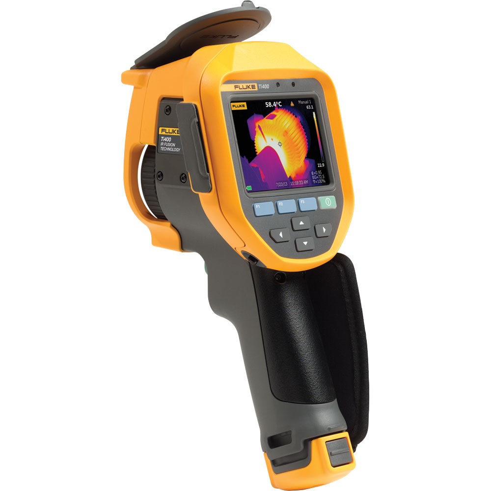
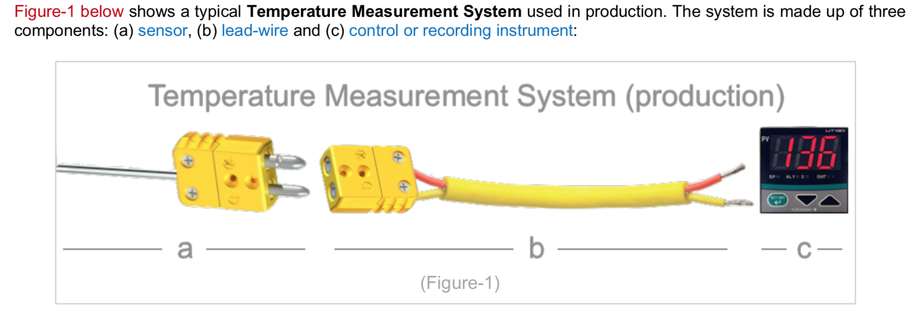
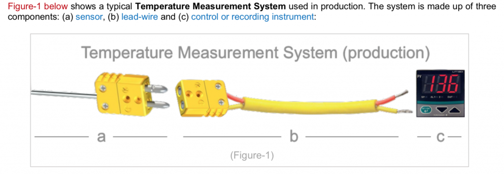
“No matter the heat-treating process being carried out, complying with AMS-2750 and/or CQI-9 requires that the heat treater measure, record, and control several different variables. One of the more common variables that must be measured, recorded, and controlled is process temperature.

Measuring process temperatures requires the use of a precise measurement system (Figure-1 below), and the accuracy of said measurement system must be periodically validated to ensure its ongoing compliance.”

“The validation process is carried out through a series of pyrometric tests (Instrument Calibration and SAT), and historically these validation processes are highly error-prone.

In order to help ensure process instrumentation, process temperatures, and any other variable that impacts quality is properly validated it is good practice to begin automating compliance processes whenever and wherever possible. C3 Data helps automate all furnace compliance processes using software.”

A “Standard” Mindset

Gunther Braus (dibalog) chimes back in with some pertinent wisdom: “It is not sufficient only to record, you must live the standards like CQI-9, AMS, Nadcap or even your own standard you have set up, so you must survey the data. However, in the old times, there was a phrase: the one who measures, measures crap. In the end, it is all about surveillance of the captured data.

Where you store the data is a question of philosophy: personally, I prefer local storage in-house. Yes, we all talk about IOT, etc., and I do not want to start a discussion about security; it is more about accessing the data. No internet, no data. So simple. We are overly dependent upon cloud usage on the internet.

The automation of the instrumentation precision is so much effort in terms of automated communication between testing device and controller, from my point of view we are not there yet.”

A Look at the Standards In and Outside the Industry

Interesting question! writes Peter Sherwin (Eurotherm by Schneider Electric).

The aim is to record the true process temperature seen by the components being treated. However, there are many practical factors that can alter the accuracy of the reading. From the position of the thermocouple (TC), the TC accuracy (over time), suitability of the lead or extension wire, issues with CJC errors and instrument accuracy as well as electrical noise impacting the stability of the reading.

The standards do a good job to help by prescribing the location of TC, accuracies required for both TC and instrument, and frequent checks over time through TUS and SAT checks but note the specification requirements are maximum “errors”. And if you truly want to reach world-class levels of process control and reap the inherent benefits of better productivity and quality, you should aim to be well inside those tolerances allowed.

With 30yrs+ of data required to be stored (in certain cases, particularly aerospace), there should be some thought as to how and what form this should be stored in. There are many more options of storage when the data is in digital format.

  • Paper is very costly to store and protect.
  • The virgin data file should be secure and tamper-resistant and identical copies made for backup purposes held offsite.
  • The use of FTP is becoming more common to move files automatically from the instrument to a local server (with its own backup procedures to ensure redundant records in case of disaster).
  • Regular checks should be made to examine the availability and integrity of these electronic records.
  • Control and Data Instrument suppliers should ideally have many years of supplying instrument digital records with systems that can access even the earliest of data record formats.

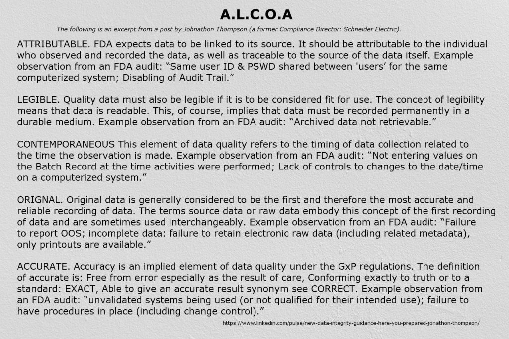
We also look outside of the heat treat standards for truly best practices. The FDA regulation 21CFRPart11 and associated GAMP Good Automated Manufacturing Practice have been extended with the new document “Data Integrity and Compliance with Drug cGMP, Questions and Answers, Guidance for Industry”. These updates leverage A.L.C.O.A to describe the key principles around electronic records (see below). This industry is also leading the requirement for sFTP a more secure format of the FTP protocol.


Heat Treat Today will run this column regularly featuring questions posed to and answered by industry experts about controls. If you have a question about controls and/or data as it pertains to heat treating, please submit it to doug@heattreattoday.com or editor@heattreattoday.com.

Heat Treat Control Panel: Best Practices in Digital Data Collection, Storage, Validation Read More »

Heat Treat Tips: How to Install an Ammonia System

During the day-to-day operation of heat treat departments, many habits are formed and procedures followed that sometimes are done simply because that’s the way they’ve always been done. One of the great benefits of having a community of heat treaters is to challenge those habits and look at new ways of doing things. Heat Treat Today101 Heat Treat Tips, tips and tricks that come from some of the industry’s foremost experts, were initially published in the FNA 2018 Special Print Edition, as a way to make the benefits of that community available to as many people as possible. This special edition is available in a digital format here.

In today’s Technical Tuesday, we continue an intermittent series of posts drawn from the 101 tips. The category for this post is Industrial Gases, and today’s tip #39 comes from Dan Herring, “The Heat Treat Doctor®”, of The Herring Group. 


Heat Treat Tip #39

How to Install an Ammonia System

Dan Herring,  “The Heat Treat Doctor®”, of The Herring Group

One of the keys to any successful ammonia system installation in the heat treat shop is to find a supplier who is capable of providing premium grade (also known as metallurgical grade) anhydrous ammonia. This product has little or no water, which could contaminate your process. Look for a specification of 99.995% ammonia.

Once you have picked a supplier, there are several choices when it comes to ammonia storage. For the lowest product price, you should consider a tank of at least 10,000 gallons (43,000 pounds of ammonia.) This allows you to purchase full 38,000-pound tanker trucks of ammonia to reduce your supply costs. One pound of ammonia yields 22.5 cubic feet of vapor or 45 cubic feet of dissociated ammonia (75% H2, 25% N2).

In most states, you must comply with these standards if you have more than 10,000 pounds of anhydrous ammonia on site. So, you need to make sure you comply with OSHA’s Process Safety Management (PSM) and EPA’s Risk Management Plan (RMP).

The second option is to keep below the 10,000-pound threshold by installing a 1,000 gallon (4,400-pound capacity) or a 2,000 gallon (8,800-pound capacity) storage tank. Pricing for ammonia into these tanks runs about 50% higher in the smaller quantities. Even with the lower inventory, you will need to comply with OSHA 1910.111 and any applicable state, city, or county laws. It is critical to check with local agencies to make sure you are in full compliance with these regulations.

Another option for smaller usages are ammonia cylinders, but if stored inside the factory, special containment cabinets are required. Check with your ammonia supplier for the details.

With regard to the installation, in most cases, you need to pour a foundation for the tank, provide electricity to the tank for a sidearm vaporizer (used to maintain pressure in the tank since you will be withdrawing ammonia vapor to the process) and provide piping from the tank to your process. Most suppliers can lease the tank and valves/attachments for a nominal monthly fee depending on your ammonia consumption. You can also add a telemetry unit that allows your supplier to monitor your tank level via an Internet site. You will need to install a water shower near the tank and have gas masks close to the tank. It is a good idea to provide a fence around the tank if your company does not have security. Your supplier should provide hazardous awareness training for ammonia.

You can expect relatively trouble-free operation from a properly installed and well-maintained ammonia supply. Maintenance problems, other than an occasional paint job, are usually minimal but good inspection (including all valving) and frequent leak checks are mandatory. The tank should be visually inspected yearly, probably by your supplier, and the pressure relief valves should be changed every five years.

Submitted by The Herring Group

Photo credit: Video Stock Footage from QuickStock.com


If you have any questions, feel free to contact the expert who submitted the Tip or contact Heat Treat Today directly. If you have a heat treat tip that you’d like to share, please send to the editor, and we’ll put it in the queue for our next Heat Treat Tips issue. 

Heat Treat Tips: How to Install an Ammonia System Read More »

UBQ Furnace Installation Expands Production Capacity

Several universal batch quench (UBQ) furnaces were purchased and installed over the course of 2018 to support the growth in business of a commercial heat treating operation located in Richland Hills, Texas.

Modern Heat Treat, which provides services such as alloy quench and temper flame hardening and carburizing to the metalworking industry, added the UBQ furnaces along with companion equipment to its installed base, increasing capacity of the equipment already in operation at the facility. AFC-Holcroft , a member of the Aichelin Group, fulfilled the orders for Modern Heat Treat, which has benefitted from the modular, flexible UBQ design with the ability to add new equipment to their facility incrementally.

Tracy Dougherty, VP Sales, AFC-Holcroft

“These large capacity UBQ furnaces provide Modern Heat Treat with a distinct advantage in the market since the equipment is scalable to meet their need for flexibility,” said Tracy Dougherty, Vice President of Sales at AFC-Holcroft. “AFC-Holcroft is proud to be a part of the continued expansion and growth of Modern Heat Treat.”

Modern Heat Treat operates a 25,000 sq ft facility with 57 employees and over 40 pieces of furnace equipment.

UBQ Furnace Installation Expands Production Capacity Read More »

Heat Treat Tips: Alloy Fabrications

During the day-to-day operation of heat treat departments, many habits are formed and procedures followed that sometimes are done simply because that’s the way they’ve always been done. One of the great benefits of having a community of heat treaters is to challenge those habits and look at new ways of doing things. Heat Treat Today‘s 101 Heat Treat Tips, tips and tricks that come from some of the industry’s foremost experts, were initially published in the FNA 2018 Special Print Edition, as a way to make the benefits of that community available to as many people as possible. This special edition is available in a digital format here.

Today, we offer one of the tips published under the Alloy Fabrications category. 


Alloy Fabrications

Heat Treat Tip #1

Allow for Thermal Expansion

When bringing furnaces to operating temperature, always be aware of thermal expansion of your alloy components. Muffles, retorts, radiant tubes all expand with heat input. These components must be free to expand within the furnace or early failure may result.

Heat Treat Tip #40

Consider Corrugated Inner Covers

Inner covers are a component of the batch annealing process in the steel industry. If your inner covers are vertically corrugated, consider horizontally corrugated inner covers instead. Horizontally corrugated inner covers are repairable and, for this reason, offer longer overall life and better value.

Heat Treat Tip #52

Batch Rotary Retorts — Stay Put and Stay Clean

Batch rotary retorts are positioned on furnace rollers at the front of the furnace. In time, these retorts expand until they no longer track on the rollers. Extend the life of your batch rotary retorts by using adjustable roller brackets (available from Alloy Engineering). And to keep the outlet tubes clean, use Alloy Engineering pig-tails and augers to self-clean batch rotary retort outlet tubes.


These tips were submitted by Alloy Engineering

Heat Treat Tips: Alloy Fabrications Read More »