HARDNESS TESTERS TECHNICAL CONTENT

Understanding Heat Treatment Specifications

Metallurgists need accurate specifications in order to correctly perform the necessary heat treatment of parts. This helpful guide, written by William Rassieur, Sales Leader at Paulo Heat Treating, is a useful tool to identify what details ought to be communicated to the heat treating expert. Read below to understand the terms to pass along.


William Rassieur, Sales Leader, Paulo Heat Treating

Too often, metallurgists receive inadequate heat treatment specifications. Some specs contain too little information. Some are unclear. Some are just plain wrong.

In any case, inadequate specs mean heat treaters don’t have the information they need to deliver finished parts that can stand up to the applications intended by their manufacturers. Avoiding the confusion and delays that follow comes down to understanding what heat treaters need to see in heat treatment specifications so that the right treatment is applied.

Make certain your parts get the appropriate treatment by including the following information:

Clearly identified materials

The chemical makeup of a part is one of the most critical determinants of how it is heat treated. It’s not enough to state on the spec that a piece is steel alloy. Consult materials standards and use the correct material designation on the spec.

For example, if you want to treat a carbon steel or an engineering alloy, using those terms (or known trade names for a specific material) isn’t adequate. Good heat treatment specifications include the material as expressed in the standards—AISI 1040 for a carbon steel, for example, or SAE 4140 for an engineering alloy.

Specific process required

It’s not enough to tell a heat treater you’d like a harder part because there are many ways to do that. Does it need to be through hardened? Case hardened? Does it require stress relief via annealing?

Specs that dictate which process is to be used help heat treaters shape the rest of the heat treatment steps that follow.

Hardness tolerance

For through hardened parts, a prescribed hardness should be included on the spec and expressed as a range. Tolerances are always more useful than uniform hardness levels because parts can have different hardness values in different regions due to material thickness or closeness to an edge.

Engineers should note that the materials and dimensions of a part affect how well it hardens out. As these variables change, so does the acceptable hardness tolerance that should appear on a spec.

Case depth tolerance

For case hardened materials (i.e., those that are carburized or carbonitrided), specs should indicate whether the desired hardness is expressed as effective case depth or total case depth.
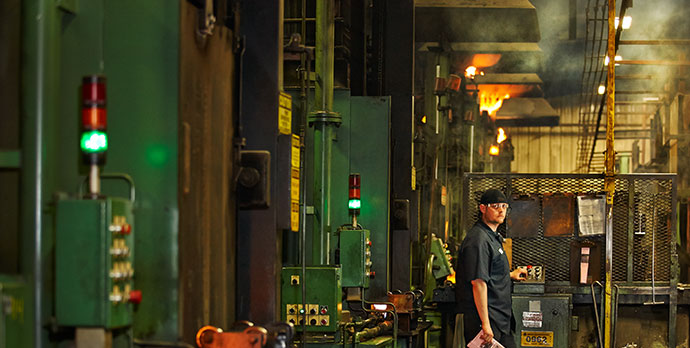
Case Hardening (photo source: Paulo.com)

Total case depth refers to the distance carbon has diffused into the part. This is usually specified for parts that have thinner case depths after treatment. Effective case depth applies to parts with generally thicker cases. This is measured as the distance from the surface through the case to a specific hardness level. Usually, that hardness is effective based from 50 or 52 HRC. This should always be stated on specs.

Heat treatment specifications should also identify the case tolerance, or the range of depths the prescribed hardness should reach. For example, a good spec for the heat treatment of a theoretical gear might state the effective case depth should be between 0.007 and 0.012 inches at the prescribed hardness.

As with through hardening, it’s more useful and realistic to specify minimum and maximum case depths rather than to write specs with a single case depth. Specs that include only minimum or maximum case depths still leave too much to interpretation and should be avoided.

Avoid too much information

Sometimes, though, too much specificity can lead to trouble. Specs that include too much process information can paint metallurgists into a corner, forcing them to abide by strict requirements that can end up thwarting their efforts to deliver improved parts.

For example, if a tempering spec includes both a specified temperature and a specified hardness, the hardness may not be possible to achieve due to differences in equipment. In such a scenario, metallurgists advise that specs be amended to call for a minimum temper as long as the part’s configuration and material hardenability are capable of achieving it.

Correct hardness scales
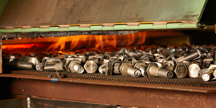
The scale on which a part’s hardness is determined depends on the heat treatment applied to the part. In the U.S., we typically use the following four hardness scales: Rockwell Hardness, Brinell Hardness, Microhardness, and Leeb Hardness. Become familiar with each scale and which parts and processes should be tested with each.

Also note that conversions between hardness scales should be avoided unless it’s absolutely necessary. That’s because hardness values are approximate; converting from one approximation to another compounds variation and could lead heat treaters and owners to incorrectly assume the prescribed hardness has been achieved.

Inspection points

Heat treatments are carefully designed to achieve specific results on specific areas of parts, so owners need to clearly identify those areas on which hardness tests are to be conducted.

For example, the critical part of the theoretical gear mentioned above is its teeth; case hardening is designed to strengthen that part of the gear while leaving other areas relatively soft and ductile. Applying a hardness test anywhere else but the teeth won’t inform heat treaters of whether the treatment was successful.

Be prescriptive with heat treatment specifications

Problems with heat treatment specifications are one of the biggest —and perhaps the most avoidable— pain points in the relationship between a manufacturer and heat treater. Manufacturers need finished parts that perform as promised. Armed with accurate and descriptive heat treatment specifications, heat treaters can deliver that performance.

For more information, contact the quoting team at Paulo or download Paulo's guide for in-house versus out-source handling of heat treatment needs.
 

(photo source: original article)


Understanding Heat Treatment Specifications Read More »

Manual Versus Automated Hardness Testing

When it comes to hardness testing nowadays, the process does not have to be done manually; automation has taken much of the burden away from operators. But which way produces the better result?

In this Heat Treat Today Original Content feature, Buehler recently published the results of a time study that compared case hardness testing of automotive crank pins and journals using both automation and manual testing. Find out which method showed a definite edge over the other in terms of time saved, less part manipulation, fewer errors in data transcription, and lower variability between performing tests.


EXECUTIVE SUMMARY

A study shows an operator time savings of 86% for making and measuring indents in three locations of crank pins and journals when using automation compared to manual testing. There was less part manipulation, fewer errors in data transcription and lower variability between operators performing tests.

INTRODUCTION

A large automotive manufacturer wanted to investigate the potential time savings of using automation for hardness testing crank pins and journals. Their existing process required two skilled operators per shift, two shifts per day, seven days per week. Tests were performed in three specified locations, two at forty-five degrees off axis and one perpendicular to the axis. Specified locations are critical, as missed locations could lead to manufactured parts being held in quarantine until further confirmation can be performed. Also of concern are failed parts that were inadvertently passed being installed and ultimately being prone to catastrophic failures. Data transcribing error was also a concern; if part information was entered incorrectly in a separate database it would cause mismatched data to lot number. When this occurs, it causes parts to become quarantined until the part information can be verified. With the total scrap cost being a considerable factor, skilled trained operators are needed for testing. Round robin testing is also used to determine the variability between operators. Qualifying new lines put into production increased testing by a factor of three to five times the normal operation analysis rate.

OBSERVATION

Current Process Observation

An evaluation of time to make and measure Vickers indentations on automotive crank pins and journals was established to determine a baseline of time for the existing process. Testing was done on a standalone manual system and required operator time for alignment, making and measuring of indents. The operators would fixture parts in similar orientation to ensure that measurements of the forty-five degree axis were in close proximity to expedite testing and reduce errors in testing. A high degree of manipulation for part alignment is necessary prior to physical testing to ensure accuracy.

It was observed that the operators’ set up time for location took the largest amount of testing time at 60%, measuring indents taking the second largest amount of time at 30% and making indents the third largest amount at 10%. The total amount of indents per pin and journal varied but averaged eighteen indents per section; six in each location. Total amount of indents for a crankshaft, pins being measured top dead center and bottom dead center and journals being measured along split, was 216 indents on average. The total analysis time for making and measuring indents at the specified locations on a crank was nine hours with 8 hours of operator interaction.

Implemented Process

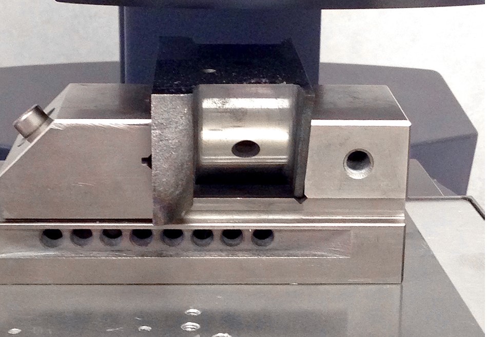
For the implemented process a Wilson VH3100 series Vickers Microhardness Tester with DiaMet software was used. Parts were clamped in a machinist vice and placed on the stage without manipulation of orientation.

Figure 1.1 – Crank pin held in machinist vice (source: Buehler)

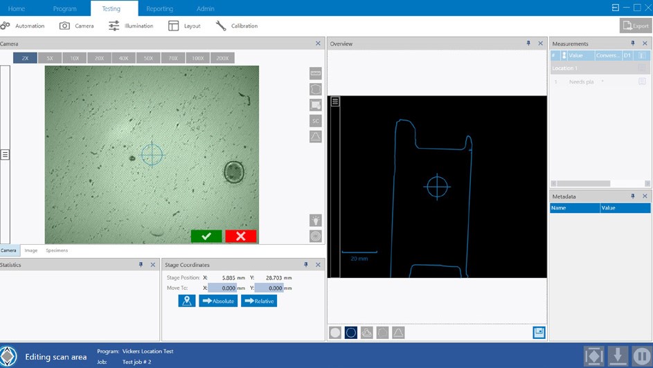
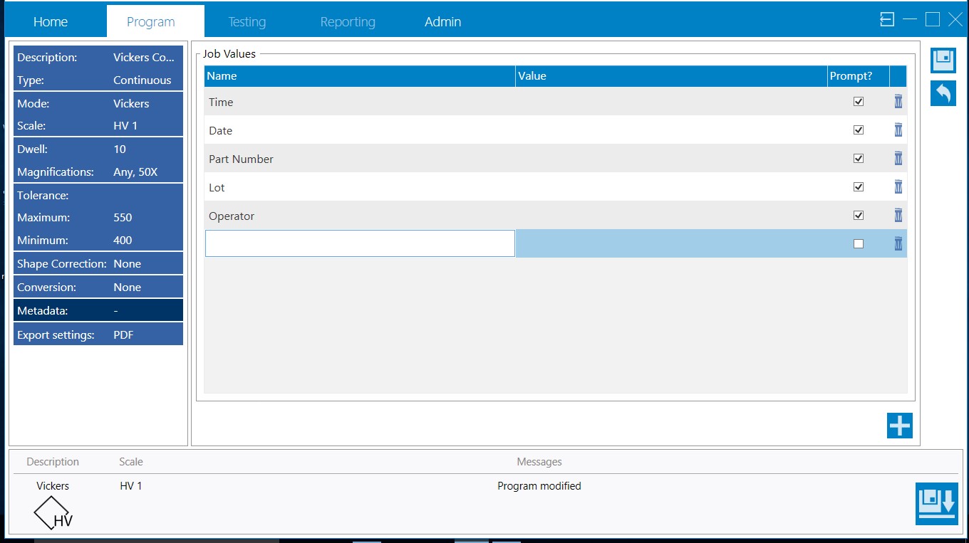
Trace function was used with the overview camera to create a template of the part to be tested; minimizing the set up time for the indent locations. The use of the template reduced the location set up time to 45 seconds in the three areas; two at forty-five degrees and one perpendicular to case.

Figure 1.2 – Trace function template for ease of indent locations (source: Buehler)

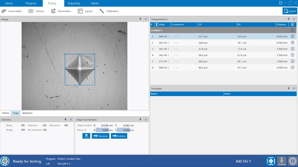
The DiaMet software snapped the template to the part at the specified location and the operators confirmed location. Observation of the set up time, making and measuring indents was 10, 50 and 40 percent respectively. Total amount of indents for a crankshaft was 216 indents on average with of time 1.25 hours with 15 minutes of operator interaction.

Figure 1.3 – Indent make and measure being performed automatically (source: Buehler)

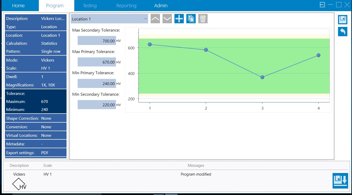
Visual high and low threshold warnings were added to each program giving the operator the ability for quick assessment of parts versus the confirmation after all crank pins and journals were analyzed as it was in previous methodology.

Figure 1.4 – Visual high low threshold warnings to alert operators of
hardness thresholds (source: Buehler)

For reporting, metadata was set up to prevent operator errors in transcribing data.

Figure 1.5 – Metadata setup to reduce operator input transcription
errors (source: Buehler)

SUMMARY

The time study evaluation shows automation saves a significant amount of time with setup as well as the time required to make and measure the Vickers indents. The total amount of time that the operators spend setting the indent profile, measuring and compiling data is reduced by 86% as well as avoiding any errors in transcribing data. Repeatability of testing is increased operator to operator, as variability between operator judgement is eliminated. The combination of using trace function and templates eliminated the need for operators to spend time aligning parts on the stage as well as mitigated the risk of a misplaced indent profile. The increase of visibility of part failure is evident at time of measurement and gives the operator the ability to recheck either an area or total part without the need for extended quarantine of parts for re-examination. Using metadata fields within the Vickers testing program removed transcribing issues which would hold up batches of cranks until records could be reviewed.

(source: Buehler)

Manual Versus Automated Hardness Testing Read More »

In-Situ Hardness Testing of Large Aerospace Structures – A Case Study

This article originally appeared in Heat Treat Today’s March 2019 Aerospace print edition.


How a Custom Designed Fixture and Hardness Testing Unit Solved a Major Aerospace Engine Manufacturer’s Hardness Testing Dilemma

Situation: A major aerospace engine manufacturer wanted to ensure the appropriate hardness of a specific section of a heat-treated engine housing. They wanted to non-destructive test the actual housing and not test shims. They wanted to do the test in-house so as to not stall production by having to ship the part out for testing. Another reason they did not want to ship the parts out for testing was the size of the parts. Some of the parts had a diameter as large as 40 inches (102 cm), 20 inches (51 cm) high, and 900 lbs (400 kg). The aerospace company also wanted an automated, full-proof system that reduced the chance of human error.

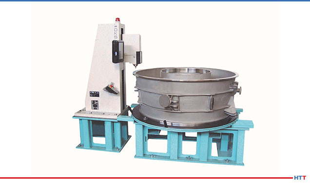
Figure 1

Solution: The solution came in the form of a custom-built hardness testing machine and an innovative fixture to hold the engine housing. As can be seen in Figure 1, AFFRI USA, located in Illinois, designed a fixture to hold both a custom-designed hardness testing machine as well as a fixture to hold the engine housing.

The Hardness Testing Machine

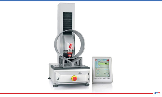
The specific hardness testing unit chosen for the job was DAKOMASTER 300. Typically, this unit is a tabletop unit as shown in Figure 2. For this specific aerospace application, the unit was modified so that it could be securely attached to the steel

Figure 2

construction holding fixture. Additionally, the custom-built unit was adapted so that the measuring head had a much greater vertical and horizontal range to accommodate varying height engine housings. The engine housings varied in size from as large as 110 inches (2.8m) in diameter and 39 inches (1m) high to the smallest being approximately 16 inches (400mm) in diameter and 9 inches (250mm) tall. The typical vertical working distance range on the tabletop unit is approximately 12 inches (300mm) while the custom unit has a vertical working distance range of 39 inches (100cm). The measuring and loading head of the unit was designed so that no misalignment would occur with the engine housing. If effective, the machine utilized what can be considered a self-clamping technology that structural deflection is absorbed ensuring an accurate and absolute reading in varying test conditions. Finally, to eliminate potential operator error, once in place, the test is initiated by a single button eliminating the need for operator engagement.

The Fixture Table

Since part and machine stability is critical for accurate hardness tests, providing a stable base for the large aerospace parts was a critical part of the solution. The company wished to execute multiple tests in multiple locations around the flange face of the engine housing. Some tests were to be conducted on the outer edge of the housing and some tests were to be conducted on the inner edge of the housing. To do this, the fixture holding the engine housing was designed so that the entire housing could move closer to or further away from the test machine. Additionally, the housing had to be rotated so that the machine could test completely around the perimeter of the housing flange face. To accomplish this, the part fixture was equipped with heavy-duty bearings so that the entire engine housing was able to be easily rotated. Once rotated to the desired location, the table would move closer to or further away from the test machine to pinpoint the exact spot for the test.

The Results

Simply stated, the results were excellent. Hundreds of tests have been run on a wide range of engine housing diameters, all with success – all well within the 1% tolerance. Being able to conduct in-house testing has helped smooth production. Having hardness testing equipment that is flexible enough to handily negotiate large or small engine housings saved the company money from needing to purchase several hardness testing machines and fixtures. Tests can be run quickly and simply by rotating the part fixture table and operator error has been virtually eliminated with the single push-button equipment. The hardness testing equipment provided for this aerospace company is capable of performing HRC, HRB, HRT, HRN measurements all in conformance with ASTM E-18. HTT

About the Author: AFFRI is an Italian-based international designer and manufacturer of state-of-the-art hardness testing systems for over 60 years. The company’s North American headquarters is located in Wood Dale, Illinois. This article originally appeared in Heat Treat Today’s March 2019 Aerospace print edition and is published here with the author’s permission.

In-Situ Hardness Testing of Large Aerospace Structures – A Case Study Read More »

Heat Treater Performs Brinell Hardness Testing with Precision for Primes

The largest subcontract heat treater of aluminum alloys in the UK, accredited to process components to Prime specifications, turned to a manufacturer of Brinell hardness testing machines to develop a more efficient testing process.

Foundrax BRINtronic automatic Brinell microscope

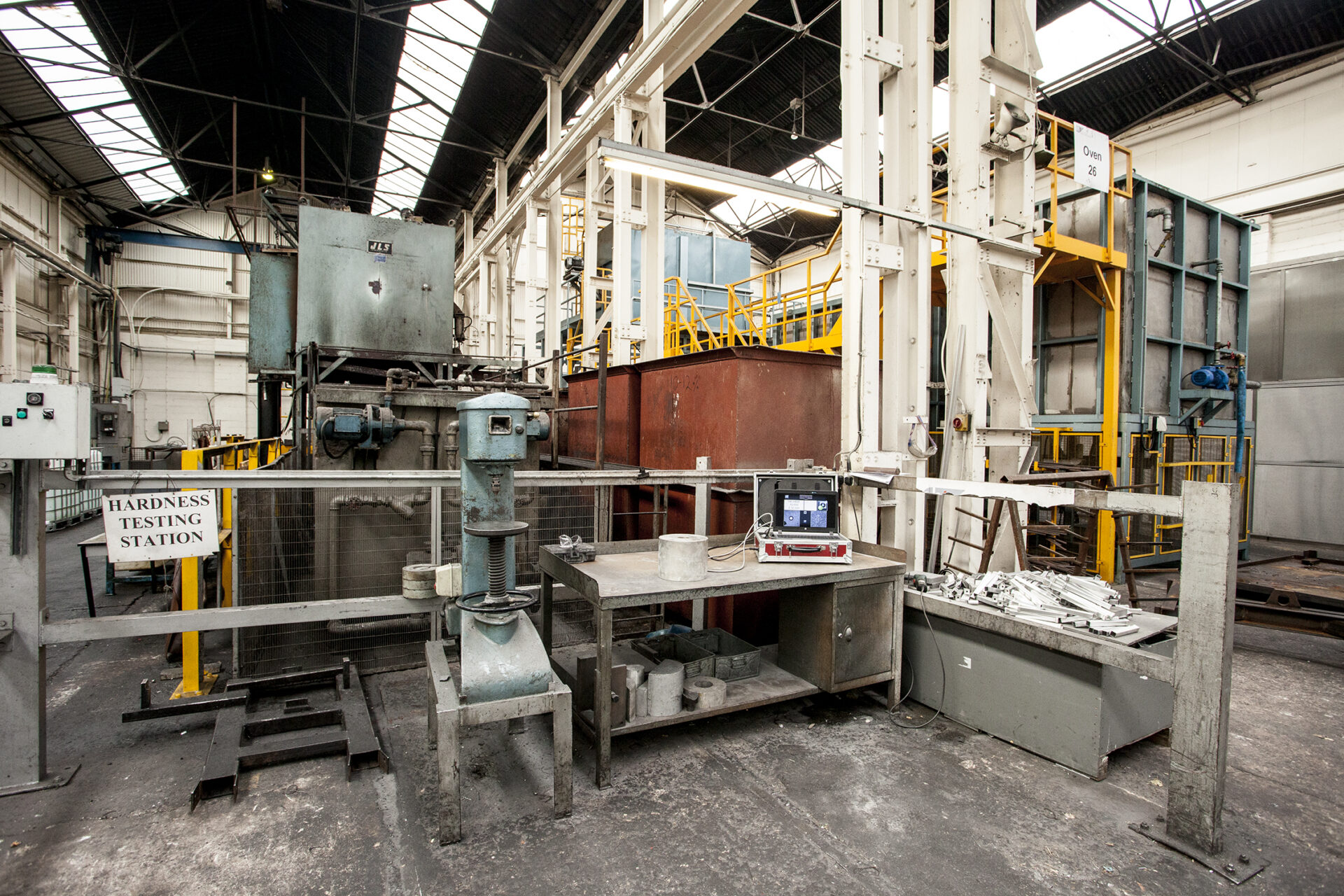
Alloy Heat Treatment (AHT), which serves the aerospace, automotive, energy, and other sectors, has a large number of prime customer approvals including Leonardo Helicopters, Airbus, Safran, Boeing, and BAE Systems. They are accredited to heat treat to these Prime’s specifications and often work as a trusted supplier to other companies that deal directly with them. Part of the Prime specifications dictates that Brinell hardness testing is carried out prior to releasing the components. AHT settled on the Foundrax BRINtronic automatic Brinell microscope, designed by Foundrax Engineering Products, based in Wessex, England.

“Part of the release process for aluminum alloys is that we must do conductivity and hardness testing on every job that leaves us,” said Steve Roberts, Quality Director with Alloy Heat Treatment. “As such we were looking at ways that we could gain efficiencies in this process. Using the BRINtronic from Foundrax has allowed us to gain these efficiencies.”

Brinell hardness measurements were required to be taken in areas of components where access is limited by intricate machine webbing or where the nose diameter of the microscope is restricted to approximately 30mm.

Alex Austin, Managing Director, Foundrax

“One of the problems we needed to solve with equipment selection is that the microscope must get into quite intricate places,” continued Roberts. “All the other microscopes we looked at have wide noses on them so, the design of the Foundrax scope was right up our street. We’ve used the manual Foundrax microscopes for as long as I’ve been here.”

“As the microscope automatically measures the indentation at multiple points, results are instant,” said Alex Austin, Managing Director of Foundrax. “They are recorded, and of course, the operator doesn’t have to turn the microscope 90 degrees and remeasure as he would with manual measurement. There is well over a 50% saving on measuring time.”

Foundrax BRINtronic display

“Obviously, the usability of the BRINtronic suited us,” said Roberts, “because we could get it into the places that we would struggle with using the competitor’s equipment. The process of measuring was far easier with the Foundrax BRINtronic as with the others we had to try and hold it with both hands and press buttons. They weren’t particularly well balanced either so in practice we were losing efficiencies rather than gaining them.”


Main photo caption: Steve Roberts of AHT uses the BRINtronic testing machine from Foundrax.

Heat Treater Performs Brinell Hardness Testing with Precision for Primes Read More »

Sacrificial Lambs: Hardness Testing and Heat Treating


Source: Gear Technology


Charles D. Schultz, president of Beyta Gear Service

In a recent blog post at Gear Technology, Charles D. Schultz, president of Beyta Gear Service, addressed the importance of accuracy when describing hardness test location and the reason why “sacrificial lambs” are needed during production.

“I cannot emphasize enough that if you are not cutting up parts or coupons you do not know what is really happening during your thermal processing.” ~ Charles D. Schulz


Read more: “Gear Materials: More Inside Heat Treating Trivia”

Photo Credit: Gear Technology

Sacrificial Lambs: Hardness Testing and Heat Treating Read More »

Tackling the Hard-ness of Hardness Testing


Source: Struers.com


Hardness testing in heat treating has evolved to a precision science necessary to provide reliability in resolving yield strength of metal materials and to assist in comparing property differences of two materials, ultimately determining “the success or failure of a particular heat-treatment operation” (Daniel Herring, “Common Pitfalls in Hardness Testing,” Gear Solutions Magazine).

According to Herring, “The Heat Treat Doctor®” (see his Heat Treat Today consultant’s page here), “Hardness testing is thought to be one of the easiest tests to perform on the shop floor or in the metallurgical laboratory, but it can be one of the hardest tests to do properly.”

Today’s Best of the Web feature offers an easy-to-follow primer on this hard testing process, providing the following:

  • Definition of Hardness Testing
  • How Hardness Tests Work
  • Selecting the Best Hardness Test Method
  • The Four Most Common Indentation Hardness Tests: their uses, suitability, and distinctives
  • How to Ensure Accuracy and Repeatability in Hardness Testing
  • Surface Preparation Requirements for Hardness Testing
  • Definition of Hardness Testing Loads
  • Indent Spacing
  • Troubleshooting for Hardness Tests

For a teaser, consider this excerpt from the article from Struers:

Factors that influence hardness testing

A number of factors influence hardness tests results. As a general rule, the lower the load you use in the hardness test, the more factors that need to be controlled to ensure an accurate conclusion of the hardness test. 

Here are a few of the most important factors to consider to ensure an accurate conclusion from a hardness test.

  • External factors such as light, dirt, vibrations, temperature, and humidity should be controlled
  • The tester and stage should be secured on a solid horizontal table, and the sample should be clamped or held in a holder or anvil
  • The indenter should be perpendicular to the tested surface
  • Illumination settings should be constant during the test when using Vickers, Knoop, or Brinell
  • The tester should be recalibrated/verified every time you change the indenter or objective lens


Read more: “Hardness Testing Is a Key Element in Many Quality Control Procedures and R&D Work”

Photo credit: Struers

Tackling the Hard-ness of Hardness Testing Read More »

What’s Going on Inside Your Heat Treated Part?


Source: Gear Technology


It’s no secret to heat treaters that not all methods work well on all parts and specifications. It’s also a hard fact that false readings can result when applying hardness measuring systems, therefore, says Charles D. Schulz of Gear Technology, “critical service parts often require a few ‘sacrificial lambs’ to be processed along with the production parts.”

“I cannot emphasize enough that if you are not cutting up parts or coupons you do not know what is really happening during your thermal processing.” — Charles D. Schulz


Read more: “Gear Materials: More Inside Heat Treating Trivia”

Photo credit: Gear Technology


What’s Going on Inside Your Heat Treated Part? Read More »

Updated MPIF Standard 35 Refers to Heat Treatment of Alloys


Source: 3DEO


A new update on MPIF Standard 35 was issued in October 2017 by the Metal Powder Industries Federation (MPIF) for aluminum alloys often used in aerospace applications, providing design and materials engineers with performance requirements for specifying aluminum alloys in powder metallurgy. The new standards identify a Rockwell hardness of 75 for the AC-2014-32-T8 and 83 for the AC-2014-38-T8, values which refer to the heat treatment which the alloys undergo.

Read more: “New Powder Metal Alloys Added to MPIF Standard 35”


Updated MPIF Standard 35 Refers to Heat Treatment of Alloys Read More »