Alcoa Samara (Arconic SMZ), Russia’s largest producer of fabricated aluminum and VSMPO-AVISMA Corporation, the world’s largest manufacturer of titanium ingots and forged products, have announced the operational launch of a joint venture.
Read more to find out the name of this joint venture.
Harper International, world leader in custom thermal processing solutions for advanced materials, has been awarded a contract for a high volume Rotary furnace system by Prayon, headquartered in Belgium.
The innovative reactor will be used for drying and calcining of Prayon’s advanced iron phosphate powder, a key component of lithium iron phosphate (LiFePO4) cathode materials used in rechargeable batteries for electric vehicles, and is a part of their recently announced new plant investment to supply the lithium ion battery market. The gas-fired Harper Rotary kiln will support their high volume operations with features to maximize Prayon’s production, including advanced tube features to provide enhanced reaction kinetics, gas-tight and dust-tight design, and internal heat recovery within the furnace chamber to improve energy efficiency. Prayon collaborated with Harper through their Ignite™ process during the development phase by supporting scale up planning and analysis. The Ignite™ program offers scale-up expertise and testing resources to help minimize risk and maximize efficiency for pilot and production level outputs. “Harper is focused on supporting the next generation of materials in advanced markets, and this project for the lithium iron phosphate market is a great representation of that”, commented Brian Fuller, Sales Manager for Harper International. “The material is an ideal solution for many of today’s most progressive technologies for electric power and storage battery systems, and we are proud to be a part of Prayon’s solution to supply this market.”
This is the first time in the world that titanium sheet has been used as fuel tank material for a mass produced motorcycle. Read more to find out the other features of the CRF450R.
A Tier 1 automotive supplier located in the Midwest has placed (2) orders with AFC-Holcroft for the supply of heat treating equipment related to the processing of aluminum.
The first order will consist of a Roller Hearth Homogenizing Furnace for processing aluminum products. The complete system includes a multi-position loading table, a multi-position furnace, cooling station and multi-position unload table.
The second order is for a Solution Heat Treat Line, which will also be used for processing aluminum products. This system will include charge and discharge transfer cars, a multi-position solution furnace, water quench system, multi-position age furnace, multi-position accumulation charge and discharge tables, accumulation cross-over mechanism and a tray pull-off station.
Additionally, AFC-Holcroft will provide their Remote Diagnostic Service™ during the furnace warranty period. This service provides a complete remote monitoring and diagnostic package including transmission and analysis of machine data, targeting the most common or noteworthy events and identifying root causes. The Remote Diagnostic Service transmits data automatically to AFC-Holcroft’s secure servers, eliminating the human time and cost associated with manually gathering historical data for the same purpose.
“While AFC-Holcroft is best known for providing equipment for the processing of steel components, we also have a long history of providing equipment to the aluminum industry” stated Mark Johnston, Aftermarket Equipment Sales. “This order is a further inroad into this growing market.”
Sapa Extrusions opened a new R&D lab in Troy, MI, dedicated to the development of extruded aluminum solutions for the automotive industry. Read more to find out what key disciplines will be available at Sapa Technology Americas.
This is the second in a series of articles by AMS 2750 expert, Jason Schulze. Don't miss the Q&A section at the bottom of this article and please submit your AMS 2750 questions for Jason to Doug@HeatTreatToday.com.
Introduction
Considering the abundant number of Nadcap heat treat audits performed in a single year, the area receiving the most findings is pyrometry, and within this group, system accuracy testing (SAT) is the third most common finding.
The SAT process has been refined through each revision of AMS2750 (C through E). We’ve seen SAT thermocouple requirements, for example, gradually incorporated into the tables but not within the body of the specification. Also, we’ve seen the definition of a SAT incorporated into revision D within the definitions section; however, with revision E it was added to the body of the specification.
AMS2750E presents three optional methods for performance of SATs that must be implemented; the Standard (or Regular) SAT, the Alternate SAT, and the SAT Waiver. Within this article, we will focus on the Standard SAT process.
Standard SAT Description – AMS 2750E
AMS2750E has defined the Standard SAT as:
An on-site comparison of the instrument/leadwire/sensor readings or values, with the readings or values of a calibrated test instrument/leadwire/sensor to determine if the measured temperature deviations are within applicable requirements. Performed to assure the accuracy of the furnace control and recorder system in each control zone.
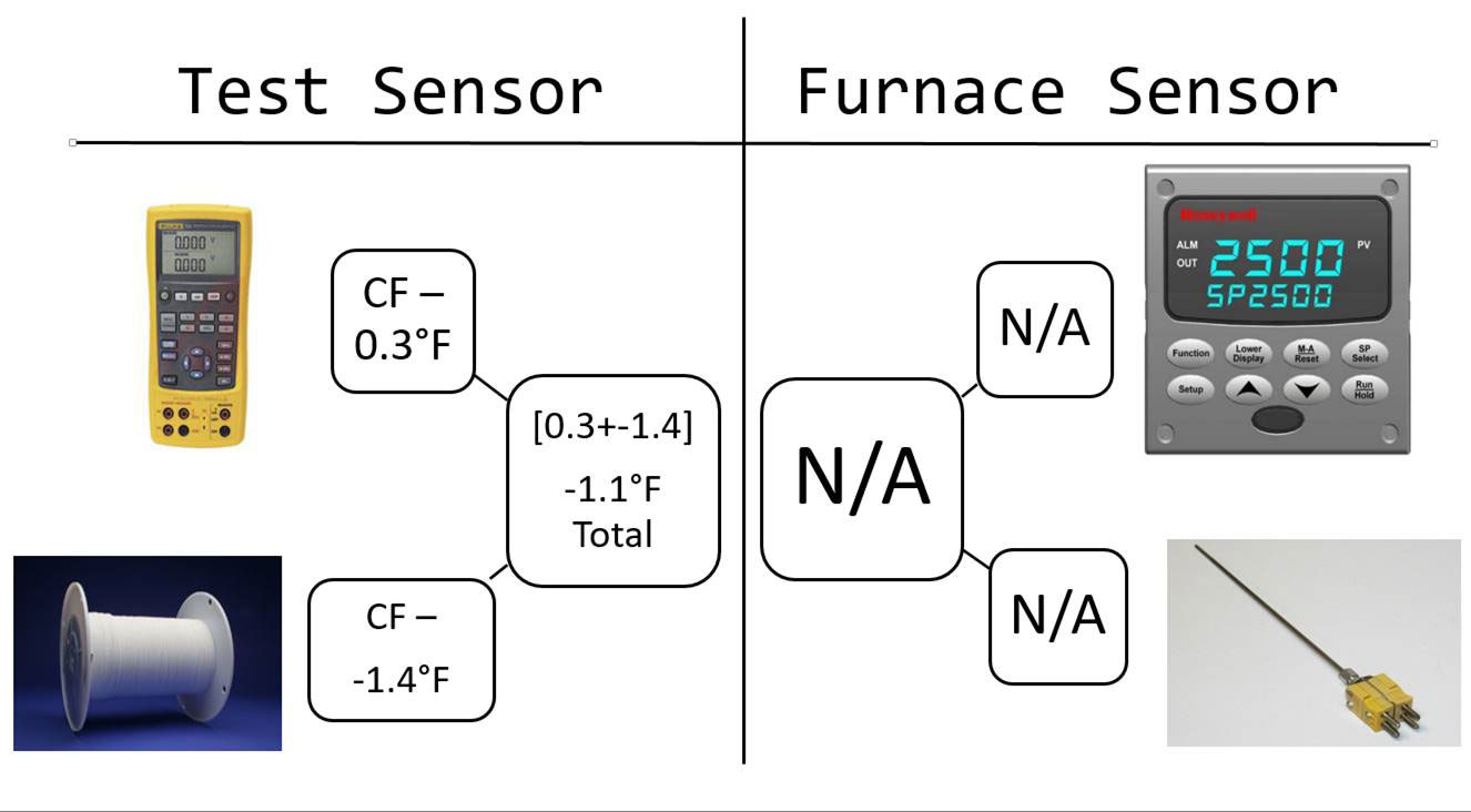
Put simply, an SAT is a comparison of two systems: the furnace system (whether control, monitoring, or load) against a test system. It’s important to recognize that the comparison is being made against two systems and not against an instrument or thermocouple alone. Each system is made up of three variables:
the instrument
the lead wire
the sensor
SAT Procedure
There is no general SAT procedure that can be applied for every supplier. Each supplier has their own needs as well as their own mechanical arrangement of thermocouples within their furnace system. The key to conformity is to ensure that, once a method for performing an SAT on a furnace is established, it is documented (i.e., in detail, including photos, if necessary) and repeated each time an SAT is performed. Some requirements to incorporate into your system are:
1) The tip-to-tip distance between the furnace system thermocouple and the test system thermocouple cannot exceed 3 inches.
2) The test thermocouple shall be in the same position/depth as the initial test.
3) The furnace is cycled and maintained at a temperature normally used during production.
4) Each system that makes up the applicable instrumentation type must be tested.
SAT Difference
Many findings arise from suppliers calculating the SAT Difference incorrectly. AMS 2750E states the following as a way to calculate the SAT Difference.
The difference calculated between the reading of the furnace sensor system being tested (sensor, lead wire, and instrument) and the corrected reading of the test sensor system (after test sensor and test instrument correction factors are applied) shall be recorded as the system accuracy test difference. Applicable correction factors shall be applied algebraically.
I’ve highlighted the word “corrected” as it applies to the test instrument systems because this seems to be a source of frequent findings. The furnace system does not get corrected, the test system does get corrected.
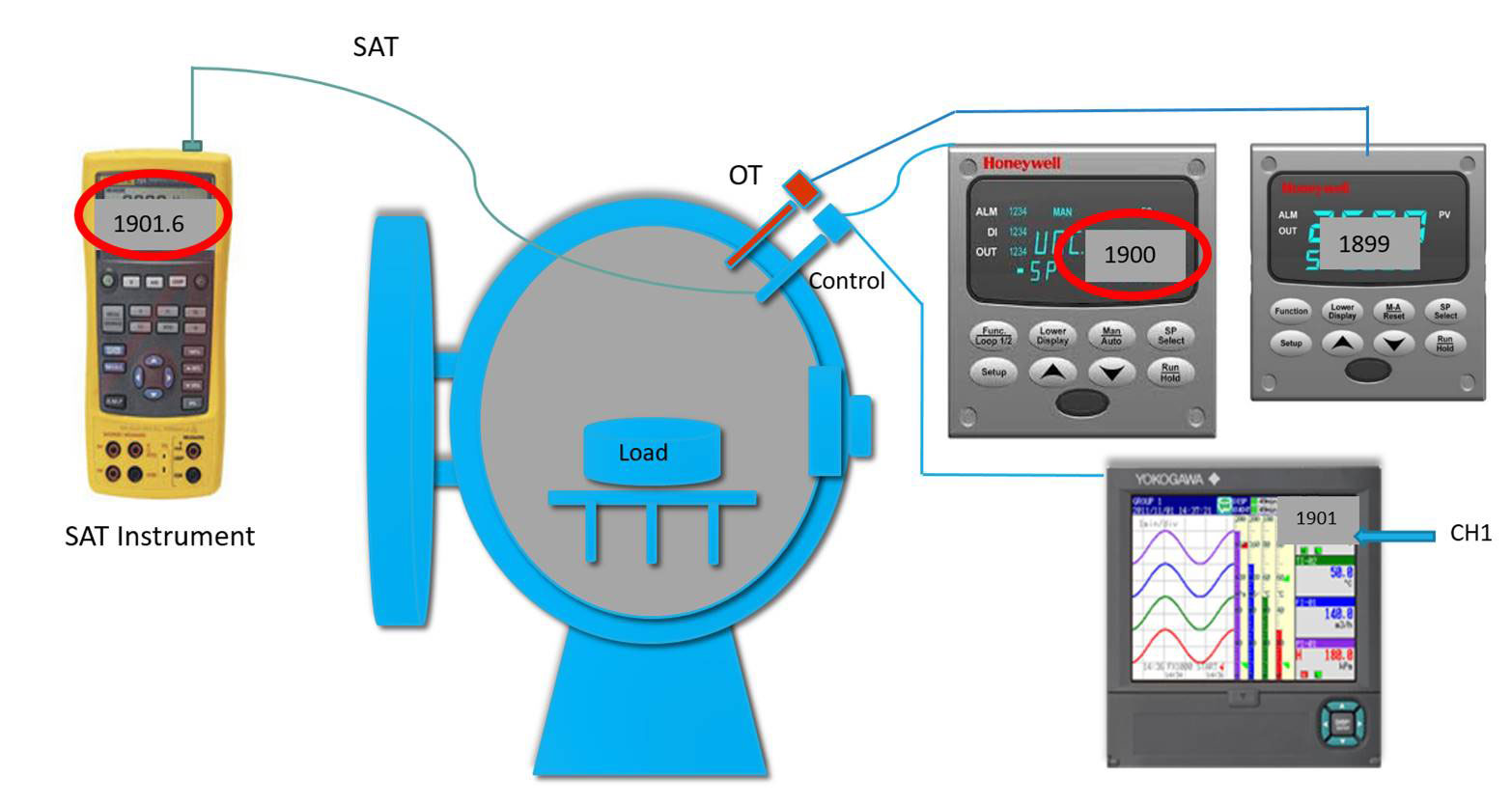
As an example, let’s consider a vacuum furnace which has had an SAT performed. The vacuum furnace is designated a Class 3 (±15°F) Type D furnace. Let’s assume no additional furnace thermocouples are employed and we are performing an SAT on the control and recording systems. The readings obtained are below in the picture.
*The example above is not an SAT Certification. It’s an example of how to calculate the SAT Difference in a given situation.
Conclusion
SATs can be difficult depending on the equipment and processes suppliers have. As always, it’s important to receive comprehensive training regarding the specific requirements of System Accuracy Testing as they apply to your facility. There are many particular aspects of SATs that may not have been accounted for in this article. If you have specific questions, please email them to doug@heattreattoday.com, and I will answer them in an upcoming article.
Submit Your Questions
Please feel free to submit your questions, and I will answer appropriately in future articles.
Out next topic will focus on the requirements and execution of an Alternate SAT per AMS2750E, the requirements of AC7102/8 and the Pyrometry Guide.
Q/A with Jason Schulz
Q: When calculating the SAT Difference, should I include the correction factors of the furnace sensor?
A: No, the correction factor from the furnace sensor is not to be included in the SAT Difference calculation.
Q: How do I account for an internal (pre-programmed) TUS offset within the controller when calculating the SAT Difference?
A: Internal or electronic TUS offset must be algebraically removed when calculating the SAT Difference. Below is an example that includes an electronic TUS offset of -2°F.
Q: I operate a furnace with 2 load sensors. One of them is used to signal the start and end of each soak cycle, the other is reference only. Do I have to perform an SAT on the load thermocouple I use as a reference only thermocouple?
A: Any thermocouple that is not used as product acceptance may be deemed reference only and is not subject to the SAT requirements of AMS2750E. Nadcap requires that the reference only thermocouples be accounted for in internal procedures.
Q: When performing my bi-weekly SAT, I get a difference of +2.6°F on one test and two weeks later I get a difference of -3°F; this constitutes a spread (within two weeks) of 5.6°F. Would this be cause for SAT failure?
A: According to AMS2750E and Nadcap, no, this would not constitute a failed SAT, though is something to be cautious of. This type of shift in SAT results does reflect some sort of change or degradation of the system being tested. A well-established tack, in this case, is to plot SAT results as part of an SPC (statistical process control) program which will govern future replacement of system thermocouples and/or leadwire (in the case when large difference is SAT results over a pre-determined amount). A documented SPC system for SAT results would also satisfy the requirements of AC7102/8(NA) page 2, paragraph 3.12.
Steel is primarily iron with up to 1% carbon, plus other alloying additions (generally totalling less than 5%).
A steel composition can be thought of as a recipe; different amounts of each ingredient make up your final product. In steel these ingredients are known as alloying additions and can affect the steel in different ways. We can affect the:
Properties of steels.
strength
hardness
toughness
ductility
fatigue
formability
machinability
weldability, and
corrosion resistance.
The addition of carbon to iron is probably the most important addition in steels which makes ‘The Iron Carbon Equilibrium Diagram’ very useful. Equilibrium means that enough time has been allowed on heating and cooling for any reactions to fully complete.
Typical Iron Carbon Diagram
In a steel <723°C, different structures are present and depending on the carbon content we can have at <0.8% Carbon – ferrite and pearlite, at 0.8% carbon – pearlite and >0.8% carbon – pearlite and cementite.
While the iron carbon diagram describes the structures of steel under equilibrium conditions, two further diagrams can be used when faster cooling rates are used; these are the CCT (continuous cooling transformation) diagram and the TTT (time temperature transformation) diagram. Both of these diagrams are helpful in selecting the optimum steel and process parameters.
When we cool a steel at faster cooling rates we can achieve additional structures, these can be bainite and martensite. CCT and TTT help determine the structures achieved.
In metallurgy the hardenability of a steel is a key parameter and when we talk about hardenability in steels we are often describing how deep into the steel we can achieve hardening. If a steel is described as having a low hardenability this will mean that the steel will produce a shallower depth of hardness. Hardenability is not to be mistaken for hardness; when describing the hardness we are often looking at the microstructure achieved during cooling. For a given steel it can be assumed that the quicker the cooling rate the greater the chance of achieving a harder structure and if that steel has a high hardenability this hard structure will be present deeper into the thickness.
In metals there are atomic defects called dislocations, these dislocations reduce the strength of the metal. The principle of strengthening mechanisms is to reduce the ability of these dislocations to move through the metal, this can be achieved by:
Atomic dislocations within the metal potentially reduce the metal’s strength.
Grain Size; the grains can interact with the dislocations preventing further movement. If we reduce the grain size we can increase the number of grains interacting with the dislocations, preventing movement and thus strengthening the metal.
Cold work introduces a large amount of strain into the metal; this strain interacts with the dislocations strain field, impeding the movement of the dislocations.
Solid solution strengthening is applied when we add other chemical elements to a metal. Addition of these elements can either be called interstitial or substitutional solid solution strengthening and will cause distortion in the atomic structure, restricting the dislocation movement and strengthening the steel.
Dispersion or precipitation strengthening is highly related to the structure of the metal and takes place when a phase is finely precipitated through a softer matrix. This precipitate acts as a barrier to dislocation movement.
The next in the series will be Steel Making and Casting.
Special thanks goes to Gary Berwick of Dry Coolers, one of our first (and best) advertisers, for informing Heat Treat Today about the below article in Airways Magazine.
MIAMI — The National Transportation Safety Board (NTSB) issued and Investigative Update of American Airlines flight AA383, which caught fire on runway 28R at Chicago O’Hare International Airport after aborting its take-off.
The report states that the right engine number 2 stage high pressure turbine (HPT) disk failed and fractured into at least four pieces. A large disk fragment landed in a UPS warehouse located about 2,920 feet (890 meters) from the aircraft.
Siemens and Panda Power Funds celebrated the commissioning of the Panda Liberty Power Project in Bradford County, Pennsylvania – an 829 megawatt natural gas-fueled power plant featuring Siemens advanced H-class gas turbines. Harnessing Marcellus Shale gas, “Liberty” is the first of two new Panda Power Funds generating stations to be commissioned in Pennsylvania this fall, with the Patriot Power Project in Clinton Township set to be dedicated in November. Combined, the two projects will be able to supply power for about two million households in large regional power markets, including Pennsylvania.
For “Liberty” and “Patriot,” Siemens’ scope of supply features advanced power generation technology, financing, and long-term service. The single shaft power plant blocks include two SGT6-8000H gas turbines, two SST6-5000 steam turbines, two hydrogen-cooled SGen6-2000H generators, and two heat recovery steam generators, along with the control system SPPA-T3000. The gas turbines and generators were manufactured at Siemens’ Charlotte Energy Hub, the global base for the company’s 60 Hz power generating equipment.
Siemens will provide maintenance and service for the main components associated with the gas turbine under a long-term service program. Parts, inspections, and scheduled service/maintenance, along with Siemens’ Power Diagnostics™ remote monitoring and diagnostics, are included in the comprehensive service agreement. For “Liberty,” Siemens Financial Services provided financing to aid in the project’s construction through a $50 million term loan.
“The commissioning of this highly-efficient power plant marks another milestone in our successful relationship with Panda Power Funds. This project demonstrates the full spectrum of Siemens’ portfolio, from our leading edge H-class technology, to financing, to service and maintenance,” said Martin Tartibi, Senior Executive Vice President, Energy Solutions Americas, Siemens Power and Gas. “As America continues to turn to cleaner-burning natural gas, we are proud that our world-class power generation technology can provide affordable, efficient and reliable power to about one million households – using the latest, most advanced emissions-control technology.”
“Designed to harness gas from the Marcellus Shale, this state of the art power plant represents the next chapter in Pennsylvania’s energy renaissance,” said Todd Carter, Chief Executive Officer of Panda Power Funds. “Working with Siemens over the last several years has proven they ‘walk the talk’ with their customer service and technological innovation, helping to bring online a world-class power asset in the Keystone State. We are very pleased to reach another important milestone in our collaboration with Siemens.”
The H-class technology in a single-shaft configuration, used in the “Liberty” and “Patriot” power stations, means that both the gas turbine and steam turbine are arranged on one shaft and drive the same generator. This design offers economic advantages as a result of low investment costs, excellent efficiency and a high degree of flexibility during operation.
The “Liberty” power project is one of seven for Siemens and Panda Power Funds in the United States, totaling over 5,800 MW. In addition to selecting Siemens to supply three Flex-Plants in Texas, Panda Power Funds chose Siemens to deliver three CCPPs in Pennsylvania – including “Liberty” and “Patriot” – and one CCPP in Virginia.





 Source: Russian Aviation Insider