Dr. Valery Rudnev, FASM, IFHTSE Fellow, was selected to be the Woodside lecturer at the most recent ASM Detroit Chapter meeting. The Woodside lecture took place on May 13, 2019, at Burton Manor in Livonia, Michigan. The title of the lecture was “Recent Theoretical and Practical Novelties in Induction Heat Treatment“.
Dr. Rudnev serves as Director of Science and Technology at Inductoheat, Inc. Known within the ASM Int’l and among induction heating professionals as “Professor Induction” for his 40+ years of experience in the heat treating industry, Dr. Rudnev centered his Woodside lecture on recent theoretical and practical novelties in induction heat treatment. He also unveiled common mispostulations associated with induction heating and frequently overlooked metallurgical subtleties.
Thermal processing by means of electromagnetic induction continues to grow at an accelerated rate, replacing alternative processes. Today’s metalworking and heat treating industry must quickly adjust to a rapidly changing business environment, maximizing cost effectiveness, process flexibility, and energy efficiency, yet satisfy continuously increasing demands for higher-quality products, equipment longevity, and environmental friendliness.
Induction heating is a multifaceted phenomenon comprising a complex interaction of electromagnetics, heat transfer, circuit analysis, power electronics and metallurgical phenomena that are tightly interrelated. Novel designs have appeared quite regularly.
The Woodside Lecture is named after William P. Woodside, who founded the American Society for Materials (ASM Int’l.) in Detroit in 1913. Each year, the chapter honors an outstanding member of
the ASM community by asking them to give the annual Woodside Lecture.
Dr. Rudnev holds more than 50 patents and inventions (U.S.and International) and has appeared in more than 250 engineering/scientific publications. He also frequently contributes content to Heat Treat Today. His most recent series, “Equipment Selection for Induction Hardening: Continuous and Progressive Hardening” can be found on Heat TreatToday’s website or in Heat Treat Today’s quarterly print editions.
Photo Caption: (from left-to-right) Dr. Robert C. McCune, FASM (Tech Chair of this event), Dr. James Boileau, ASM Detroit Chair 2018-19, and Dr. Valery Rudnev, FASM, IFHTSE Fellow (the Woodside Lecturer)
The parent company of a western Pennsylvania-base heat treat furnace manufacturer recently announced a partnership with a Serbian defense materials manufacturer to supply new heat processing equipment.
Zastava Arms, which manufactures firearms and artillery, based in Kragujevac, Serbia, replaced dated equipment with a new SECO/WARWICK high-temperature box furnace. The new equipment includes tighter temperature uniformity and fully automated temperature controls.
“We chose the SECO/WARWICK technology based on our previous experience and because it fits perfectly with our current Quality Management System by providing real-time controls that ensure a high-quality product and profitable operation,” said Vladan Živković, Manager of Department of Technology with Zastava Arms. “Zastava Arms has been a supplier to the defense industry for many decades and will stay among top defense suppliers thanks to investments in high-quality technology.”
Jarosław Talerzak, Vice President of Thermal Segment at SECO/WARWICK
According to DefenseWeb, the defense industry of Serbia is the largest in the Western Balkans and manufacturers must implement strict standards in order to meet the criteria to get a permit for manufacturing.
“We have enjoyed a long partnership with Zastava Arms and are pleased to continue supplying advanced technology solutions for every heat treatment application,” said Jarosław Talerzak, Vice President of Thermal Segment at SECO/WARWICK. “As a technology partner, we are positioned to support our customer’s growth by offering a wide range of service and equipment options especially for the very demanding industries represented by our partner.”
Main photo credit/caption: MilMag Facebook/Serbian Zastava Arms assault rifle
A Chicago-based manufacturer recently announced the construction of “the world’s largest continuous ERW tube mill,” according to the project’s supplier.
Capable of producing hollow structural sections (HSS) with a size range of 8″ square x 0.750″ wall up to 22″ square x 1″ wall, the new mill, operated by Atlas Tube, a division of Zekelman Industries, will produce square, rectangular, and round structural sections in the mill. The largest rectangular section will be 34″ x 10″ x 1″ wall, and the largest round section will be 28″ OD x 1″ wall. The new mill will produce products to meet or exceed ASTM A500, ASTM A1085, CSA G40 and ASTM A252. This will be the first time ERW sections above 16″ square will be available domestically.
The mill will also be engineered to allow for world-leading full change-over times of less than 60 minutes, as well as special forming and sizing technology for precise dimensional tolerance. Zekelman Industries selected SMS as the supplier for the mill, Kusakabe for the milling cut-off, and Mair for the material handling and packaging line.
Barry Zekelman, CEO of Zekelman Industries
The total project investment is over $150 million — the largest private investment in the U.S. steel industry in the last decade. Frank Lagac, sales manager of welded pipe plants at SMS, noted that it will be the “world’s largest continuous ERW tube mill.”
“At Zekelman, we continue with our long-standing goal of creating, not waiting for, the future, said Barry Zekelman, CEO of Zekelman Industries.
Tom Muth, president of Atlas Tube
“Over the past few years, we have seen the increasing need for larger, domestically produced HSS in the bridge, transportation, and building markets,” said Tom Muth, president of Atlas Tube. “Also, HSS with thicker walls that meet the more stringent width-to-thickness ratio requirements of the AISC Seismic Provisions are in greater demand for lateral bracing systems.”
Brad Fletcher, senior sales engineer for Atlas Tube
“This new mill gives structural engineers new tools to meet the demands of designing and building cost-efficient and safe steel structures,” said Brad Fletcher, senior sales engineer for Atlas Tube.
This article continues the ongoing discussion on Equipment Selection for Induction Hardening by Dr. Valery Rudnev, FASM, IFHTSE Fellow. Dr. Rudnev previously reviewed equipment selection for scan hardening in three parts. The first part on equipment selection for continuous and progressive hardening is here; the second part is here. To see the earlier articles in the Induction Hardening series at Heat TreatTodayas well as other news about Dr. Rudnev, click here. This installment continues a discussion on equipment selection for continuous and progressive hardening applications.
Inductor Designs
So far, I have discussed the application of conventionally designed solenoid coils in continuous/progressive hardening applications. However, even multiturn solenoid-type coil geometries may have quite complex shapes accommodating the shape of induction hardened components. One illustration of this is shown in Figure 1 where two in-line multiturn solenoid-type inductors are used for heat treating of an irregular shape component.
Figure 1. Two in-line multiturn solenoid inductor of a complex shape. (Courtesy of Inductoheat Inc., an Inductotherm Group company)
Besides multiturn solenoid coils, channel-type multiturn inductors (also called slot or skid inductors) are frequently used in continuous/progressive heat treating. The channel inductor gets its name from its similarity to a long channel. This shape allows parts to be passed through the coil in a number of ways, such as a conveyor, shuttle, indexing, rotary or carousel table, turntable, or any other indexing system.
Channel coils permit easy entry and exit of the heated components to/from the inductor. Figure 2 shows images of some examples of multiturn channel inductors. The crossover ends of channel coils are bent away to allow the part to pass through. In some cases, the crossover ends are made high enough to ensure minimum impact on the heating of the part at the ends of the coil, minimizing electromagnetic forces when workpieces enter and exit the inductor. In other cases, the opposite might be true, and crossover coil regions play an important part in providing the needed temperature distribution.
Figure 2. Images of different examples of multiturn channel inductors. (Courtesy of Inductoheat Inc., an Inductotherm Group company.)
Channel coils are used to heat treat selected regions of parts, as well as entire components. These inductors are often used for through hardening, annealing, and tempering applications. However, if a specific case depth is required, rotation of the workpiece may be needed to even case depth.
Figure 3 shows a “state-of-the-art” continuous fed induction system for heat treating fasteners [2]. This system is adjustable for a wide range of fastener/bolt diameters and lengths (0.5–4.0 in. [12–102 mm]) and is capable of production rates of up to 600 fasteners per minute. The unique proprietary coil design developed by Radyne Corporation maximizes electrical efficiency and system flexibility while preventing stray heating of electrically conductive surroundings that may potentially cause undesirable heating of structures and malfunction of electronic devices. The rotary dial tooling is designed to accept bolt fasteners from the in-line vibratory feeder. The adjustable speed rotary table contains advanced safety features to prevent damage and meltdown.
The quench assembly allows adjusting the quench flow for the utmost in quench control. After spray quenching, parts are stripped from the traverse assembly and dunk quenched into the tank for final cooling to room temperature.
Figure 3 shows a “state-of-the-art” continuous fed induction system for heat treating fasteners [2].The tooling is designed with a quick change feature to ensure that all tooling can be changed for a different part size in less than 15 minutes. The system is controlled through a controls package and HMI for part setup and part storage of different programs. Through this HMI, the power source coil “Z” adjustment can also be stored and adjusted for different bolt lengths assuring superior quality fasteners. This unit includes four sizes of tooling required for the rotary heat treat fixture and the traverse tooling: M6, M8, M10, and M12.
Besides solenoid coils and channel inductors, other inductor styles are used including split-return, hairpin and double hairpin inductors, transverse flux, and traveling wave inductors. However, an application of those inductors is not as frequent for continuous/progressive induction hardening.
Heat treat equipment upgrades were included in the investments made at a global industrial solutions company that produces fasteners and fastening assemblies.
A. Raymond Tinnerman, based in Brunswick, Ohio, has seen significant upgrades and additions to its Logansport, Indiana, facility, which includes the rebuild of the heat treating processes and the addition of an endothermic generator.
Mark Schahczinski, Sales Engineer, Wisconsin Oven Corporation
A metal treating company based in Raleigh, North Carolina, recently purchased five electrically heated standard draw batch (SDB) series furnaces to be used for stress relieving at its facility.
East Carolina Metal Treating received shipment of the equipment, which have maximum operating temperatures of 1250°F, from Wisconsin Oven Corporation, a Thermal Products Solutions company. Guaranteed temperature uniformity of ± 10°F at set points 300°F, 750°F, and 1250°F was documented with a 9-point temperature uniformity survey in empty oven chambers under static operating conditions.
“East Carolina Metal Treating has been incredible to work with,” said Mark Schahczinski, Sales Engineer, “and we look forward to working with them for many years to come. ECMT even filmed the installation process for these five batch ovens, and the time lapse video is available to watch on both the WOC and ECMT Facebook pages.”
A U.S. integrated steel producer headquartered in Pittsburgh, Pennsylvania, recently announced that it will invest more than $1 billion to construct new facilities in Pennsylvania, including a sustainable endless casting and rolling facility at its Edgar Thomson Plant in Braddock, Pennsylvania.
David B. Burritt, president and CEO of U.S. Steel
United States Steel Corporation (U.S. Steel) announcement highlights] the company’s continued commitment to steelmaking in Pennsylvania. In addition to the endless casting and rolling facility, the company plans to build a cogeneration facility at its Clairton Plant in Clairton, Pennsylvania. Both are part of the U.S. Steel’s Mon Valley Works.
The cutting-edge endless casting and rolling technology combines thin slab casting and hot rolled band production into one continuous process and, according to U.S. Steel, will make Mon Valley Works the first facility of this type in the United States, and one of only a handful in the world, replacing the existing traditional slab caster and hot strip mill facilities at the Mon Valley location.
“This is a truly transformational investment for U. S. Steel,” said David B. Burritt, president and CEO of U.S. Steel. “We are combining our integrated steelmaking process with industry-leading endless casting and rolling to reinvest in steelmaking and secure the future for a new generation of steelworkers in Western Pennsylvania and the Mon Valley. U. S. Steel’s investment in leading technology and advanced manufacturing aligns with our vision to be the industry leader in delivering high-quality, value-added products and innovative solutions that address our customers’ most challenging steel needs for the future. We believe that adding sustainable steel technology to our footprint will create long-term value for our employees, our region, our customers and our investors.”
With this investment, Mon Valley Works will become the principal source of substrate for the production of
the company’s industry-leading XG3™ Advanced High Strength Steel (AHSS) that assists automotive customers in
meeting fuel efficiency standards. This project, in addition to producing sustainable AHSS, will improve
environmental performance, energy conservation and reduce our carbon footprint associated with Mon Valley Works. First coil production is expected in 2022, contingent upon permitting and construction.
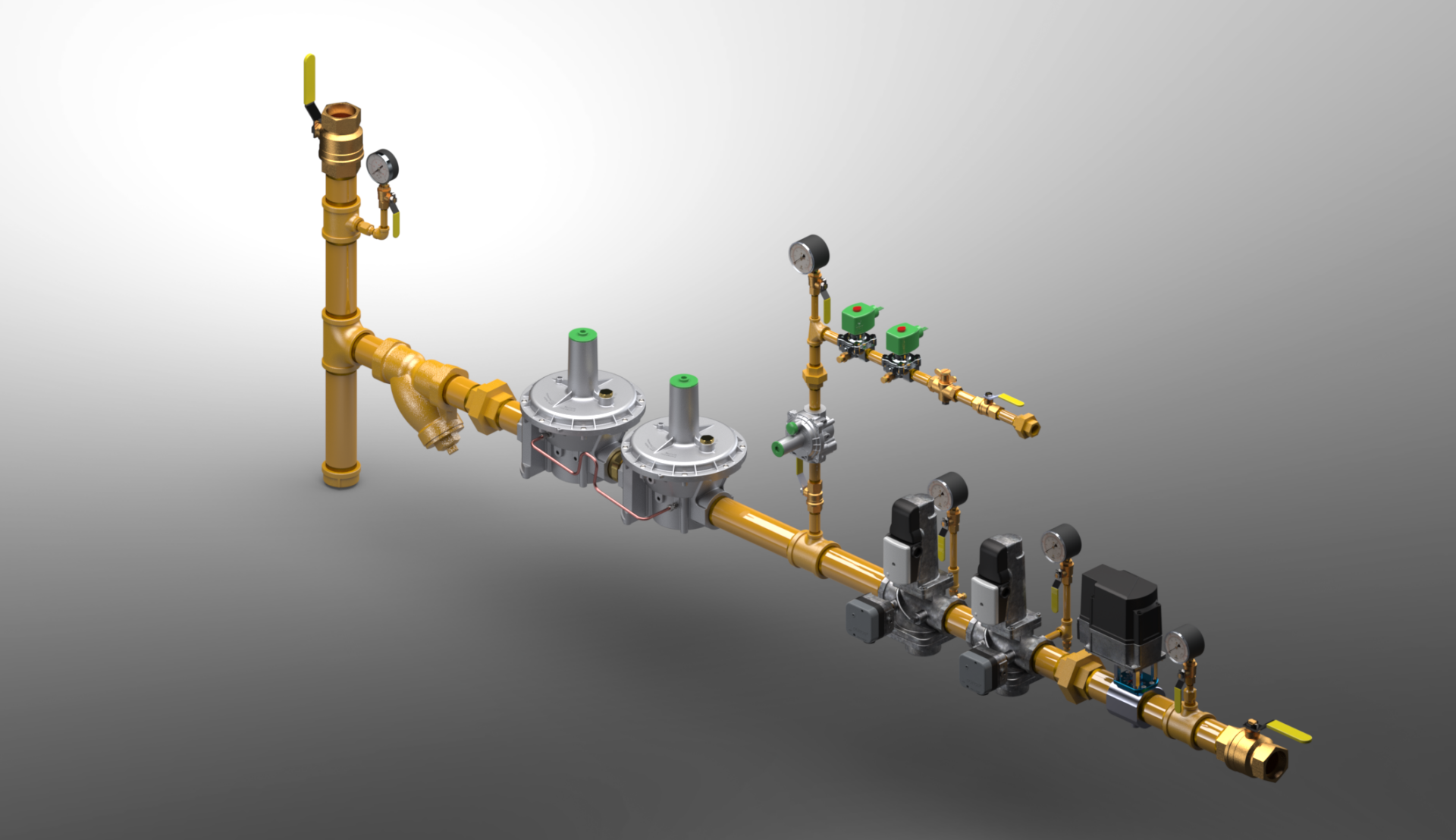
This article on the critical role of valve safety trains in the prevention of catastrophic fuel-delivery accidents at heat treating facilities is authored by Robert Sanderson, P.E., Director of Business Development in the Combustion Safety division of Rockford Systems, LLC, based in Rockford, Illinois. Valve safety trains require regular inspections, maintenance, and training.
Heat treating, a thermal process used to alter the physical, and sometimes chemical, properties of a material or coating, is a high-temperature operation that involves the use of heating or chilling, normally to extreme temperatures, to modify a material’s physical properties — making it harder or softer, for example. Applications for heat treating are virtually endless, but at the heart of all thermal processes is the valve safety train.
These fuel-delivery devices maintain consistent conditions of gasses into furnaces, ovens, dryers, and boilers, among others, making them crucial in assuring safe ignition, operation, and shutdown. Equally important, they keep gas out of the system whenever equipment is cycled or shut off.
A valve safety train isn’t a single piece of equipment. Instead, it has many components including regulators, in-line strainers (“sediment traps”), safety shut-off valves (SSOV), manual valves (MV), pressure switches, and test fittings logically linked to a burner management system.
Flame-sensing components make sure that flames are present when they are supposed to be, and not at the wrong time. Other components may consist of leak-test systems, gauges, and pilot gas controls. At a minimum, there are two crucial gas pressure switches in a valve safety train, one for low pressure and one for high pressure. The low gas pressure switch ensures the minimum gas pressure necessary to operate is present. As you would assume, it will shut off fuel to the burner if the gas pressure is below the setpoint. The high gas pressure switch ensures excessive pressure is not present. It too will shut off fuel if the gas pressure is too high. Both switches must be proven safe to permit operation. Additionally, there will be an air pressure switch to ensure sufficient airflow is present to support burner operation.
Some systems have supplementary pressure switches, such as a valve-proving pressure switch. Switches such as these are typically used to enhance safety or provide other safety aspects specific to that application’s needs. A multitude of sensors within the valve safety train — pressure switches, flame detectors, position indicators — and isolation and relief valves work together in concert to prevent accidents.
Valve safety trains must be compliant with all applicable local and national codes, standards, and insurance requirements. The most common of these for North America are NFPA, NEMA, CSA, UL, FM. Annual testing and preventive maintenance are not only an NPFA requirement, but also oftentimes required by insurance agencies, equipment manufacturers, and national standards, including ANSI, ASME, and NEC.
Set Your Trap
The primary function of a valve safety train is to reliably isolate the inlet fuel from the appliance. Safety shut-off valves are purposely selected to do this. To protect these valves, the initial section of a safety train is used to condition the fuel and remove debris that could potentially damage or hinder all downstream safety components.
The first conditioning step is a sediment trap (a.k.a. dirt leg, drip leg). This trap captures large debris and pipe scale and provides a collection well for pipe condensates. The proper orientation of a sediment trap is at the bottom of a vertical feed. This downwards flow arrangement promotes the capture of debris and condensate into the trap. A horizontal feed across a sediment trap is an improper application. The second conditioning step is a flow strainer or filter element. These devices are fine particulate sieves. The removal of fine particulates from the fuel stream further protect the downstream safety devices from particulate erosion and abrasion. Taken together these conditioning steps remove particulates and condensates that might block, hinder, erode, or otherwise compromise the safety features of the downstream devices.
The Explosive Force of a Bomb
Owing to the presence of hazardous vapors and gases, a poorly designed or inadequately maintained safety train can lead to catastrophic accidents, ranging from explosions and fires to employee injuries and death. When this explosive force is unleashed, the shock wave carries equipment, debris, materials, pipes, and burning temperatures in all directions with tremendous force.
The following incidences provide just a few examples of why it is important to purchase the highest quality valve safety train and to keep it professionally maintained, inspected, and tested.
In 2018, a furnace explosion at a Massachusetts vacuum systems plant killed two men and injured firefighters as a result of fuel malfunction.
In Japan, an automobile manufacturer lost tens of millions of dollars when it was forced to shut down production for nearly a month after a gas-fueled furnace exploded due to flammable fumes building up in the tank.
In a Wisconsin bakery, an employee was seriously injured when he ignited an oven’s gas and was struck by a door that was blown off. A malfunctioning valve had allowed natural gas to build up inside the oven.
In 2017, a van-sized boiler exploded at a St. Louis box company, killing three people and injuring four others. The powerful, gas-fueled explosion launched the equipment more than 500 feet into the air.
In 2016, a boiler explosion in a packaging factory in Bangladesh enveloped the five-story building in flames, killing 23 people.
Two Dangers: Valves and Vents
Valves are mechanical devices that rely upon seats and seals to create mechanical barriers to control flow. Over time, these barriers wear out for a variety of
Glassblowing Furnace with Pipes
reasons, whether it is age, abrasion, erosion, chemical attack, fatigue or temperature. Increased wear contributes to leaks, and leaks lead to failures and hazards. Defective valves can allow gas to leak into a furnace even when the furnace is not in operation. Then, when the furnace is later turned on, a destructive explosion could occur.
Testing a valve’s integrity is an evaluation of current barrier conditions and may be used to identify a valve that is wearing out prior to failure. As such, annual valve leakage tests are an important aspect of a safety valve train inspection program. Along with annual testing, valves should be examined during the initial startup of the burner system, or whenever the valve maintenance is performed. Only trained, experienced combustion technicians should conduct these tests.
Improper venting is another danger. Here is the problem: Numerous components in a valve safety train require an atmospheric reference for accurate operation. Many of these devices, however, can fail in modes that permit fuel to escape from these same atmospheric points. Unless these components are listed as “ventless,” vent lines are necessary. Vent lines must be correctly engineered, installed, and routed to appropriate and approved locations. In addition, building penetrations must be sealed, pipes must be supported, and the vent terminations must be protected from the elements and insects. In short, vent lines are another point of potential failure for the system.
Even when vent lines are properly installed, building pressures can vary sufficiently enough that they prevent optimal burner performance. Building pressures often vary with seasonal, daily weather, and manufacturing needs, further complicating matters. Condensate in vent lines can collect and drain to low points or into the devices themselves. Heating, cooling, and building exhausters are known to influence building pressures and device responses, but so can opening and closing of delivery doors for shipping and receiving. Hence a burner once tuned for optimal operation might not be appropriately tuned for the opposite season’s operation.
The smart alternative to traditional vented valve trains is a ventless system that will improve factory safety and enhance burner operation. Ventless systems reference and experience the same room conditions where the burners are located, resulting in more stable year-round operating conditions, regardless of what is happening outside. Additionally, ventless designs typically save on total installation costs, remove leaky building penetrations, eliminate terminations that could be blocked by insects, snow or ice, improve inspection access, and ensure a fail-safe emergency response.
Final Thoughts
Valve safety trains are critical to the operation of combustion systems. Despite being used daily in thousands of industrial facilities, awareness of their purpose and function may be dangerously absent because on-site training is minimal or informal. To many employees on the plant floor, this series of valves, piping, wires, and switches is simply too complex to take the time to understand. What is known can be dangerously misunderstood.
Understanding of fuel-fired equipment, especially the valve safety train, is necessary to prevent explosions, injuries, and property damage. The truth is, although valve safety trains are required to be check regularly, they are rarely inspected, especially when maintenance budgets are cut. And while codes require training, they offer very little in terms of specific directions.
As a safety professional, the onus is on you. You and your staff must have a core level of knowledge regarding safe practices of valve safety trains, even if a contractor will be doing the preventive maintenance work. Most accidents and explosions are due to human error and a lack of training when an unknowing employee, for example, attempts to bypass a safety control. Preventive maintenance is essential to counter equipment deterioration, as is the documentation of annual inspection, recording switch set points, maintaining panel drawings, and verifying purge times. Accidents happen when this type of documentation is not available. Don’t wait for a near-miss or accident to upgrade your valve safety train.
DC53 Steel, a general purpose cold work mold and die steel with exceptional strength and resistance qualities, is nonetheless “only as good as the heat treatment it receives,” according to our Best of the Web resource today. Not surprisingly, manufacturers find these excellent characteristics for machining applications.
The folks at International Mold Steel, Inc., a steel distributor in Florence, Kentucky, have compiled a primer on heat treating DC53, which is known not only for its strength and resistance, as mentioned, but also for have a higher hardness than D2 after heat treatment. This is critical for machining shops where die and mold life expectancy is dependent upon proper high-temperature tempering and high hardness.
A University of Texas at Arlington thesis student recently investigated thermal annealing to determine how to increase inter-bead bond strength overall in 3D printing processes.
Rhugdhrivya Rane tackled the dilemma of weak tensile strength in FDM parts and whether parameters chosen by the user — such as temperature ranges and pressure gradients — can affect an increase in inter-bead bond strength. The researcher used thermal annealing, and thermal annealing with unidirectional mechanical pressure in the Z direction, 3D printing a variety of specimens in ABS. The method of 3D printing was chosen due to its increased popularity in mainstream manufacturing.
“The parts were printed using two different sets of print parameters: high and low settings, to investigate the effect of heat treatment on both sets of print parameters. The values of temperature, time and applied pressure during heat treatment were varied to obtain a detailed comparative study and the correlation between the given variables and the increase in ultimate tensile strength.” ~ Rane
The discovery was that “higher temperatures and longer exposure to heat produced better tensile strength, along with increased ductility.”
“Though thermal annealing and uniaxial pressure cause an increase in the strength of the parts, the print parameters play a vital role in determining the initial mechanical properties of the parts. When the parts are fabricated with a higher value of flow rate and extrusion temperature, they exhibit significantly higher mechanical properties as compared to parts printed with substandard setting,” concluded the researchers. “Thus, by controlling the print parameters and using the right values of temperature and pressure we can see substantial increase in strength of FDM parts.”
Photo credit/caption: via UTA / “Tensile testing of dogbone specimens”


![Figure 3 shows a “state-of-the-art” continuous fed induction system for heat treating fasteners [2].](https://www.heattreattoday.com//wp-content/uploads/2019/05/FIG_3.jpg)