
Two Cost-Effective Applications for Intensive Quenching of Steel Parts
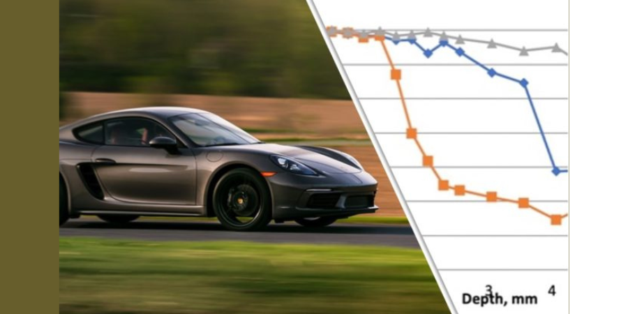
![]() The Intensive Quench (IQ) process is an alternative way of quenching steel. It involves a very rapid and uniform cooling of steel products in water with cooling rates several times greater than that of conventional quenching in agitated oil or polymer. Through this interesting article, explore the unique method and its use in the automotive industry.
The Intensive Quench (IQ) process is an alternative way of quenching steel. It involves a very rapid and uniform cooling of steel products in water with cooling rates several times greater than that of conventional quenching in agitated oil or polymer. Through this interesting article, explore the unique method and its use in the automotive industry.
This article first appeared in Heat Treat Today’s August 2021 Automotive print edition Edward Rylicki, vice president of Technology, and Chris Pedder, technical manager of Heat Treat Products and Services, at Ajax TOCCO Magnethermic Corp., as well as Michael Aronov, CEO of IQ Technologies, Inc.
Introduction
The Intensive Quench (IQ) process is an alternative way of quenching steel parts that originated with Dr. Nikolai Kobasko of Ukraine in 1964.1 It involves a very rapid and uniform cooling of steel products in water with cooling rates several times greater than that of conventional quenching in agitated oil or polymer. The IQ process is interrupted at an optimal time when the surface compressive stresses reach their maximum value, and the part-hardened layer reaches its optimal depth. A proprietary computer program is used for determining an optimal dwell time for steel parts of different shapes and dimensions.
Ajax TOCCO Magnethermic Corporation has recently acquired assets of IQ Technologies, Inc. of Cleveland, Ohio. Over the last 20 years, IQ Technologies has been commercializing an intensive quenching (IQ) process for steel parts in the U.S. and overseas.

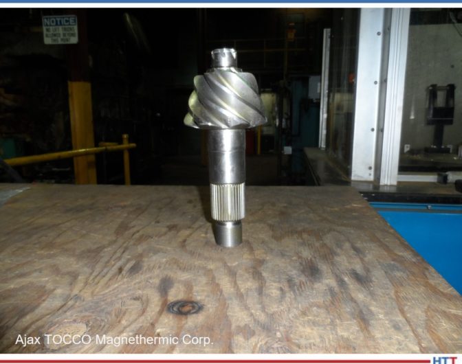
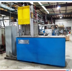
The IQ process is conducted in IQ water tanks (a batch IQ technique) and in single-part processing high-velocity water flow IQ units when parts are quenched one at a time. Steel parts are austenitized prior to intensive quenching in heat treating furnaces or using an induction through heating (ITH) method.2 As an example, Figures 1 and 2 present two production IQ systems. Each includes a single-part processing high-velocity water flow unit built by IQ Technologies. The IQ unit in Figure 1 is equipped with a single-shot low frequency ITH station built by Ajax TOCCO Magnethermic. It is designed for processing gun barrels and shafts of up to 36” long and up to 2” in diameter. The IQ unit in Figure 2 is equipped with a box atmosphere furnace and is designed for processing gear products of up to 8” in diameter and shafts of up to 15” long.

Coupling of the single-part processing IQ technique with the ITH method (ITH + IQ) is the most effective way of IQ process implementation. It allows conducting of heat treating operations within a manufacturing cell in line with a steel parts production process. This paper focuses on two applications of the ITH + IQ process:
- Elimination of a costly, energy and time-consuming carburization process
- Substitution of a one-step ITH + IQ process for a two-step heat treatment consisting of batch quenching parts in oil or polymer for part core hardening followed by induction hardening
Elimination of Carburizing Process
The carburizing process is the most expensive and time-consuming heat treatment process. Elimination of the carburizing process by implementing the IQ method requires the use of limited hardenability (LH) steels. LH steels are medium to high carbon steels having exceptionally low content of alloy elements. When quenched intensively, LH steels provide a hard, martensitic case, tough, ductile core, and high residual surface compressive stress mimicking a carburized condition without carburization.
Two IQ case studies were conducted with two major U.S. automotive parts suppliers for evaluating the IQ process when applied to side pinions and drive pinions made of LH steel. Results obtained were compared to the same parts made of alloy steel, carburized and quenched in oil.
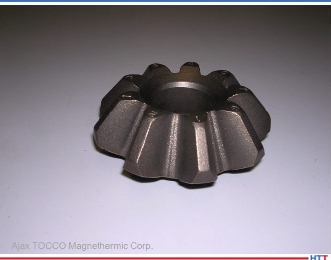
Side Pinions
Figure 3 presents a picture of the evaluated side pinion having the outside diameter (OD) of 80mm and inside diameter (ID) of 27mm. Standard pinions were made of alloy 8620 steel, carburized, quenched in oil, and shot peened. Pinions made of LH steel (acquired from Russia) were quenched intensively in the high-velocity water flow single-part processing IQ unit. The LH steel pinions were not shot peened after heat treatment. A chemical composition of the LH steel used is presented in Table 1.

To evaluate the side pinion structural and stress conditions during heat treatment, DANTE computer simulations were conducted by DANTE Solutions, Inc. of Cleveland, Ohio, for standard carburized side pinions and for intensively quenched pinions made of LH steel.3 It was shown that the microstructure of the carburized and quenched-in-oil side pinion consists of martensite formed within the part carburized case and bainite in the remaining part cross section (Figure 4).

A microstructure distribution in the intensively quenched side pinion made of LH steel consists of a martensitic structure in the part surface layer, a bainitic structure beneath the martensitic case, and a perlitic structure in the part core. The martensitic case is generally deeper in the intensively quenched LH steel pinion compared to that of the standard pinion.
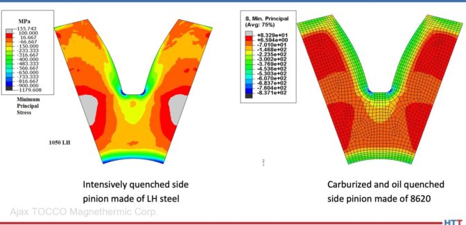
Figure 5 presents calculated values of the minimum principal stress that represent residual surface compressive stresses. As seen from the figure, the intensively quenched LH steel side pinion has residual surface compressive stresses greater than that of the carburized side pinion quenched in oil.

Figures 6–8 present experimental data obtained by the customer for the intensively quenched side pinions made of LH steel. Figure 6 shows hardness profiles at the pinion pitch line, tooth root, and tooth tip. Figure 7 presents an etched pinion tooth sample showing a martensitic case. As seen from the above figures, the IQ process provided the hard case and the ductile core that mimics a hardness distribution after carburizing.
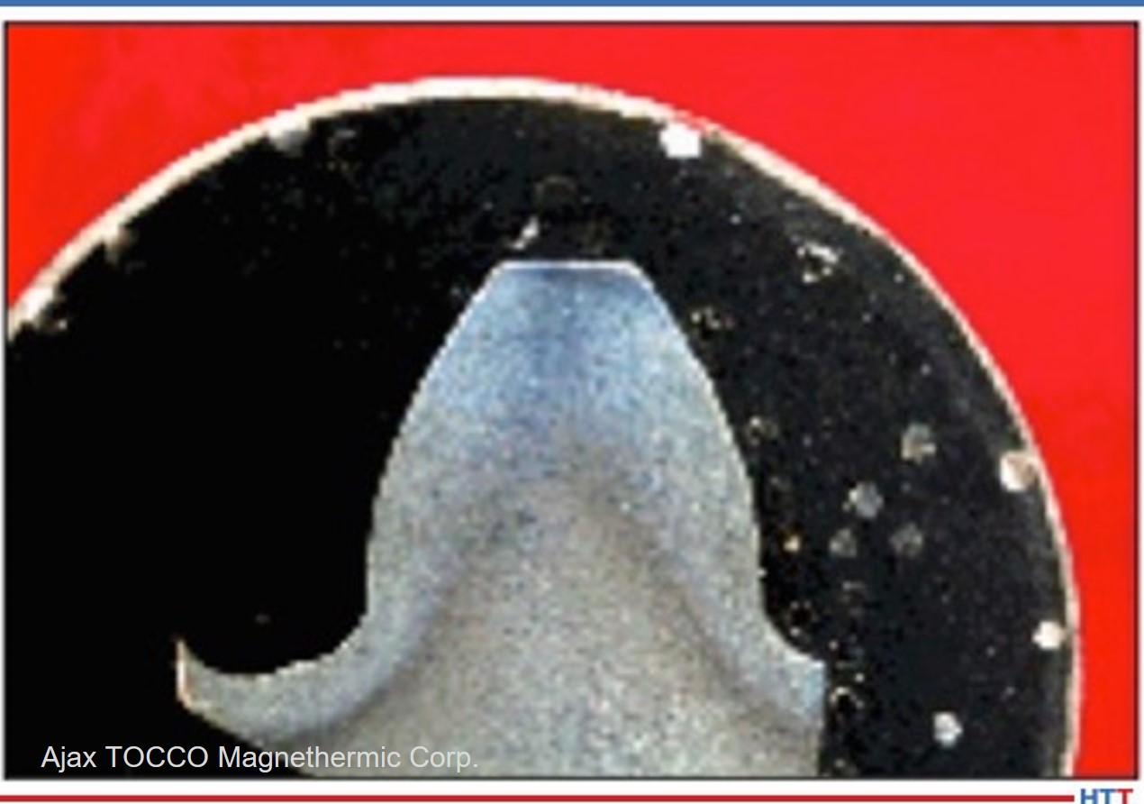
Figure 8 shows a residual surface compressive stress distribution for the LH steel side pinion root area. Residual surface compressive stresses for the intensively quenched side pinion made of LH steel were greater than that of the standard carburized and shot peened pinion. Fatigue testing has proven that intensively quenched side pinions made of LH steel have a longer service life compared to the standard pinions.

Drive Pinions
An IQ case study was conducted for drive pinions with one of the major U.S. automotive parts suppliers. Drive pinions were made of LH steel produced by a U.S. steel mill (the LH steel chemistry is proprietary information). Figure 9 presents a picture of the evaluated drive pinion. The drive pinions were quenched in the high-velocity water flow single-part processing IQ unit. Per customer evaluation, the hardness profile in the intensively quenched drive pinions made of LH steel mimics the hardness distribution in the standard carburized and oil quenched drive pinions, while the values of the residual surface compressive stresses are greater for the intensively quenched LH steel pinions compared to that of the standard drive pinions. (This information is also not presented in the paper due to its proprietary nature.)
The intensively quenched drive pinions met all the customer’s metallurgical specifications and passed both the ultimate strength test and the fatigue test. It was shown that the part fatigue resistance improved by about 150% compared to that of standard carburized and quenched in oil drive pinions. In addition, distortion of the intensively quenched drive pinions is so low that no part straightening operations are required.
Application of the ITH + IQ process and LH steels for side pinions and drive gears will result in the following major benefits:
- Less energy usage due to elimination of the long carburization process
- Lower overall part costs
- Cleaner parts and work environment due to use of water instead of quench oil or polymers
- Lower work-in-process inventories and shortened lead times, due to possibility of running heat treat operations in part manufacturing cell
Substitution of One-Step Heat Treating Process for Two-Step Heat Treatment
A two-step heat-treating process consisting of batch quenching of parts in oil or polymer for core hardening, followed by induction hardening, is used in the industry for many steel products. This heat-treating process provides parts with a hard case and tough, ductile core that is similar to the carburizing process. A substitution of the ITH + IQ method for the two-step heat-treating process is another attractive possibility for steel part makers in reducing the part cost.

One of the major U.S. automotive parts suppliers applied this approach to the manufacturing of input shafts (Figure 10). The input shafts are currently made of high-alloy medium-carbon steel that requires annealing after forging. The intensively quenched input shafts were made of plain medium carbon steel that did not require annealing after forging. The shafts were quenched at the Ajax TOCCO Magnethermic Detroit Development & Support Center.
Per customer evaluation, the hardness profile in the intensively quenched input shafts was similar to that of standard shafts. Residual surface compressive stresses in the intensively quenched shafts are greater compared to that of the standard input shafts resulting in longer part fatigue life of up to 300%. (Per the customer’s request, the actual data on the part hardness profile, microstructure distribution, and values of residual surface compressive stresses are not presented in the paper.)
Figures 11 and 12 present current and improved input shaft production flow charts accordingly. As seen, an introduction of the ITH + IQ process allows elimination of the following input shaft manufacturing steps: annealing after forging, batch oil quenching, and shaft straightening. In addition, part shipping and material handling operations will be significantly reduced. In summary, the application of the ITH + IQ process provides the following major benefits in this case:
- Less energy usage due to the elimination of two heat treating processes: annealing after forging and batch quenching in oil
- Less material cost due to substitution of plain carbon steel for high alloy steel
- Lower overall part costs due to the use of less expensive steel, reduction of heat treatment cost, elimination of all expenses associated with the use of quench oil, reduced cost of shipping and material handling, and elimination of part straightening operations
- Cleaner parts and work environment due to use of water instead of quench oil or polymer
- Lower work-in-process inventories and shortened lead times, due to possibility of running heat treat operations in part manufacturing cell


Conclusion
Implementation of the ITH + IQ process and the use of LH steels will make possible the conducting of heat treat operations in a steel part manufacturing cell, reducing work-in-process inventories and shortening lead time. At the same time, tremendous energy savings, significant reduction of a carbon footprint, and overall part cost can be achieved due to eliminating the carburizing process and the use of quench oil, and due to the substitution of plain carbon steel for high alloy material. Improved work environment is also a bonus.

IQ Facility at Ajax TOCCO Magnethermic Detroit Development & Support Center
Ajax TOCCO Magnethermic has set up an IQ facility at its Detroit Development & Support Center (Figure 13). The facility includes a single-part processing IQ unit and an induction heating station. The IQ unit is capable of processing gear products, shafts, etc. of up to 8” in diameter and 15” long. The IQ unit controls monitor the following parameters: water temperature, water flow velocity, pump pressure, and dwell time. The induction heating fixture consists of a pneumatic horizontal indexing heat station used for power supply load matching and inductor positioning. The load matching station can be fed by numerous power supplies capable of various operating frequencies and power levels up to 600 kW.
The Detroit Development & Support Center also houses a large area for the manufacture and repair of induction tooling, along with engineers needed for the design of prototype and production tooling. There is also a metallurgical lab with the equipment and staff necessary to support the ITH + IQ process development. The metallurgical lab contains macro and micro hardness testers, cut-off wheels, polishing equipment and a metallograph for analyzing microstructures.
References
[1] N.I. Kobasko and N.I. Prokhorenko, “Quenching Cooling Rate Effect on Crack Formation of 45 Steel,” Metalloved. Term. Obrab., Met., No. 2, 1964, p. 53-54 (in Russian).
[2] M.A. Aronov, N.I. Kobasko, J.A. Powell, “Intensive Quenching of Steel Parts,” ASM Handbook, Volume 4A. Steel Heat Treating Fundamentals and Processes, 2013, p. 198-211.
[3] B.L. Ferguson, Zhichao Li, N.I. Kobasko, M.A. Aronov and J.A. Powell, “Limited Hardenability Steels and Intensive Quenching,” Proceedings of ASM Heat Treating Conference, Indianapolis, 2009.
About the Authors: Edward Rylicki is the vice president of Technology and Chris Pedder is the technical manager of Heat Treat Products and Services, at Ajax TOCCO Magnethermic Corp. For more information, contact info@ajaxtocco.com or 800.547.1527
Michael Aronov is the CEO at IQ Technologies, Inc. For more information, contact Michael at m.a.aronov@sbcglobal.com.
Two Cost-Effective Applications for Intensive Quenching of Steel Parts Read More »