Fundamentals of furnace maintenance sometimes fall between that tricky area of realizing their importance and getting pushed to the end of the to-do list. This original content piece shares tips to bring the fundamentals back to where they belong: at the top of the to-do list.
Ben Gasbarre President, Industrial Furnace Systems Gasbarre Thermal Processing Systems
Safety First | Whether the furnace is in operation, or it is having down time, proper safety measures must be in place. Personal protective equipment, proper shut down of power sources, and even the buddy system are topics taken in to consideration.
Asset Management System | Have up-to-date maintenance records available to any and all employees. "Ensuring important information, such as alloy replacements, burner tuning, or control calibration information, can help operations and maintenance personnel as they plan and assess future equipment needs," comments Ben Gasbarre, president industrial furnace systems at Gasbarre Thermal Processing Systems.
Cleaning | Reminders include: change filters on combustion blowers, clean things like burners and flame curtains, clean out endothermic gas lines, burn off manual probes at least once a week, etc.
Daniel Hill, PE Sales Engineer AFC-Holcroft Source: AFC-Holcroft
Rules and Regulations | The military and energy industries are sectors that have strict standards to follow. Different heat treating shops are using a software module to maintain furnace data, looking at data reports to make sure the furnace systems are running properly.
Timely Maintenance | Making a maintenance plan and then following it means that no tasks are overlooked or forgotten.
After Repairs and Adjustment | Make sure that after trouble shooting and performing repairs, the software generated reports are examined and that furnaces continue to be maintained. Daniel Hill, PE, sales engineer at AFC-Holcroft says, "This saves valuable time and resources, improves availability, and likely increases profitability."
Greg Steiger Senior Key Account Manager Idemitsu Lubricants America
Proper Levels of Sludge and Water Quench | Failing to keep the quench oil clean results in problems on surface finish. Maintain the quench from the start by filtering, cleaning, and replenishing to keep end product surfaces more acceptable.
Frequency of Sampling | "[The] more often a quench oil is analyzed, the easier it is to use the quench oil analysis as a tool in the proper care of a quench oil," explains Greg Steiger, senior key account manager at Idemitsu Lubricants America.
Regular Addition of Fresh Oil | Proper maintenance of quench oil will result in some loss through filtration. Be sure to replenish.
Find heat treating products and services when you search on Heat Treat Buyers Guide.com
The privilege of unveiling the Heat Treat Today40 Under 40 Class of 2022 comes with the reality that not every one of the nominees could be included in the final count; even though each young, up-and-coming, talented heat treating professional whose name was submitted is making a significant difference in their field.
The individuals pictured are those we acknowledge in 2022 for their contribution to their company, their dedication of service to their customers, and their commitment to pursue skills and knowledge to further contribute to their field.
Caleb Johnson Field Service Manager SECO/VACUUM Technologies LLC
Sergio Luevano Product Manager Nitrex
Sean Rupprecht Mechanical Engineer Gasbarre Thermal Processing Systems
Heat Treat Today will be back next year looking for rising leaders in the 40 Under 40 Class of 2023. We encourage you to consider the talented young professionals in the heat treating sphere, especially in the captive heat treatment industry, who deserve this recognition for their leadership. You can begin the process right now: Click here to nominate a young professional for Summer 2023.
CQI-9 compliance demands adherence to the standards for the purpose of excellence in automotive heat treating. Poorly maintained quench oil can cost heat treaters in many areas.
In this Heat TreatToday Technical Tuesday feature, Greg Steiger, senior key account manager at Idemitsu Lubricants America, shares how costly quench oil issues can be addressed through proper adherence to the CQI-9 quench oil testing protocols. Let us know if you’d like to see more Original Content features by emailing editor@heattreattoday.com.
Greg Steiger Sr. Key Account Manager Idemitsu Lubricants America
Introduction
A poorly maintained quench oil can cost a heat treater in more ways than simply the cost of having to replace the oil. The costs can quickly expand to include those associated with poor quality. For example, costs associated with part rejects, or rework and downstream costs for shot blasting, or third-party inspection are often the cause of poor quench oil maintenance. Dirty or poorly maintained oils can affect part cleanliness, surface hardness, and surface finish. For instance, it is well known that a heavily oxidized oil may create surface stains that must be shot blasted to remove. High molecular weight sludge or excessive water can create surface hardness issues. Many of these issues can be addressed through proper adherence to the quench oil testing protocols established by CQI-9.
How can CQI-9 help?
CQI-9 is designed as a tool to help heat treaters produce consistent parts. Using a CQI-9 compliant quench oil analysis can also be a very powerful tool in a heat treaters tool kit. Just as the level of carburization is influenced by the carbon potential of a carburizing atmosphere, the cooling speed of the oil influences microstructure formation and microstructure composition along with mechanical properties such as hardness as well as tensile and yield strength. Furthermore, the cooling speed is dependent upon the viscosity of the oil, the amount of sludge, moisture level, and oxidation of the oil. All of these are tested on a regular basis under the requirements of CQI-9, ISO TS 16949, and most quality systems adopted by modern heat treaters. All of the tested parameters required under CQI-9 will be addressed individually later in this paper.
What is CQI-9?
The member companies of the Automotive Industry Action Group (AIAG) encompassing automotive manufacturers and their Tier I suppliers have enacted an industry heat treating standard called CQI-91. This standard was originally a standalone standard designed and adhered to primarily by North American OEMs and Tier I suppliers as a quality tool to create consistent documented processes within the heat treating industry with the goal of producing consistent reproducible results. Since that first implementation of CQI-9, the standard has now been incorporated into the ISO TS 16949 standard and is now adhered to by most automotive OEMs and their Tier I suppliers. The full range of management responsibilities, material handling, and equipment operations of the CQI-9 standard is beyond the scope of this paper. Instead we will be discussing the used quench oil analysis requirements of CQI-9, why the tests are required, and how heat treaters need a CQI-9 compliant quench oil analysis to properly care for their quench oils.
Utilizing a compliant CQI-9 analysis and the supplier provided operating parameters for the CQI-9 required tests is the first step in the proper care of a quench oil.
CQI-9 Compliant Analysis
Most quench oil suppliers provide a quench oil analysis. Although the quench oil supplier may provide a quench oil analysis, for the analysis to be CQI-9 compliant the analysis must contain the following tests or their equivalent:
Water content; ASTM D6304
Suspended solids; ASTM D4055
Viscosity; ILASD509
Total acid value; ASTM D664
Flash point; ASTM D92
Cooling curve; JIS K2242
The frequency of the above testing must be a minimum of semiannually. A more frequent sampling interval does not violate CQI-9. In fact, the more often a quench oil is analyzed, the easier it is to use the quench oil analysis as a tool in the proper care of a quench oil. It is important to note that the CQI-9 standard does not prescribe specific test methods be used in the above testing; however, they must be performed to a traceable standard. The CQI-9 standard only states that the above values, along with a cooling curve, must be reported. The following sections will describe each test in a CQI-9 compliant analysis.
Water Content
Everyone knows water in a quench oil can be have catastrophic safety and performance consequences. However how much water is too much? That is a question that is difficult to answer. The answer depends on a variety of factors such as the quench oil used and all of the variables associated with a furnace atmosphere. A general rule of thumb when it comes to water levels is to keep the water level below 200PPM. At levels above 200PPM of water, uneven cooling begins to occur.2 It is important to remember a quench oil is not a pure homogenous fluid. Samples taken at various places throughout the quench tank will be similar but will also have differences. These differences will include water and solids levels. Therefore, in areas where the water content exceeds the 200PPM level, uneven cooling will begin. Parts coming into contact with this “localized” quench oil with high water can potentially begin to crack, have a high surface hardness, or have staining problems. Yet parts in other areas of the load continue to behave normally. For this reason, and also because water is much heavier than oil, it is imperative the oil be under agitation. In addition to the potential uneven cooling issues high water may create, a high level of water can also influence the rate of oxidation in an oil.
Suspended Solids
Because solids are typically denser and more viscous than liquids they do not have the same heat transfer properties as a liquid. Due to the inequality of heat transfer capacities between liquids and solids, it is very important to keep the solids level, especially high molecular weight sludge, at a minimum. Sludge reacts in an opposite manner of water. Where water can increase quench speed, high molecular weight sludge will decrease quench speed through uneven cooling.2 The result of the uneven cooling from sludge is typically seen in soft surface microstructures or soft surface hardness. Also, like water, sludge is heavier than oil and the lack of homogeneity in the oil means having proper agitation is paramount when sampling.
Viscosity
Changes in viscosity can lead to both faster quench rates and slower quench rates. As the quench oil is used in the quench process, it undergoes thermal degradation.3 This degradation process can be seen when the oil becomes thinner or less viscous. During this process, a small portion of the base oil and a small amount of the quench oil additives undergo a process called thermal cracking. In this process, heavier molecules are broken into smaller molecules through the use of heat. This thermal cracking creates lighter less viscous oil from heavier oils. The newer lighter viscosity of the quench oil can potentially lead to changes in the quench speed of the oil. These changes can have an impact on the microstructure, case depth, core hardness, and surface hardness on the quenched parts.
As an oil is subjected to the high temperatures of a quenching operation, oxidation is a natural occurrence in the oil. As the oil oxidizes it will begin to increase in viscosity until it reaches the point of forming an insoluble sludge. Therefore, an increase in viscosity typically means the oil is oxidizing. Just as an oil that becomes thinner and less viscous may have a change in cooling properties, an oil that becomes thicker and more viscous may see a change in cooling performance. A thicker oxidized quench oil may affect surface hardness, microstructure, case depth, and core hardness. In severe cases of oxidation staining may result. Such stains typically require post quench and temper processing such as shot blasting.
Total Acid Value
The Total Acid Value, or TAV, is a measure of the level of oxidation in a quench oil. The amount of oxygen in a quench oil cannot be measured without a sophisticated laboratory analysis. However, the formation of organic acids within a quench oil can be easily determined via a titration method. It is well understood that these organic acids are the precursors in a chain of chemical reactions that will eventually form sludge. As the TAV increases so will the levels of oxidation, and in turn, the amount of sludge will also increase. Consequently, as the TAV increases, the amount of staining due to oxidation may increase. The cooling properties of the oil may decrease due to the increased sludge formation as well. Figure #1 shows an example of how the acid value increases the viscosity of a quench oil due to the formation of polymeric sludge in the quench oil.2
Figure #1. Acid number vs kinematic viscosity for Daphne Hi Temp A
Flash point
The flash point of a quench oil is another check to ensure the safety of the quench oil user. As oil thermally cracks, the heavier base oils become not only lighter in viscosity, but their flash points also decrease. If left unchecked, the decrease in flash point could result in a higher risk of fire. In addition to serving as a watchdog against the results of excessive thermal cracking, a flash point is also a safeguard against human error and adding the wrong quench oil to a quench tank. High temperature oils typically have a higher flash point than conventional oils. An increase in flash point, along with no change in TAV, and an increase in viscosity could indicate a contamination issue between oils has occurred.
Cooling curve
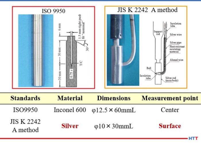
There are many different methods of running a cooling curve. Many Asian suppliers of quench oil will use the Japanese Industrial Standard (JIS) K 2242. European suppliers will use the ISO 9950 and North American suppliers rely on the ASTM D 6200 method. All of these standards measure the same basic property, the ability of an oil to reach martensite formation. However, they differ in one basic item. The JIS K-2242 and methods used in China and France use a 99.99% silver probe that is smaller than the size of the Inconel probe used in the ASTM and ISO methods of Europe and North America. Because of this difference, it is important to note that cooling curves and cooling rates between the methods should not be compared. Figure # 2 shows the comparison between the two probes and their dimensions.
Figure # 2. ASTM D-6200/ ISO- 9950 and JIS K 2242 quenchometer probes^2 ISO/ASTM Inconel probe 12.5mm x 60mm. JIS K 2242 Silver probe 10mm x 30 mm
In addition to comparing the cooling curve against the standard for the quench oil used, the Grossman H value should also be calculated and used as an indicator of cooling performance. Unlike the old GM nickel ball test that tracked the time to cool a 12mm nickel ball to 352°C, the Grossman H value measures the severity of the quench6.
In using the Grossman H value, the lower the value, the slower and less severe the quench. For use as a rough guide in comparing the quench speed in seconds to the Grossman H value measured in cm-1 the table below can be used.
Table #1
For example, air has an approximate H value of 0.01 cm-1 and water has an approximate H value of 0.4 cm-1 compared to oil with an approximate H value of ___ cm-1
The calculation used to determine the Grossman H factor has historically been:
H=h/2k
Where h is the heat transfer coefficient of the part when measured at the surface of the part and k is the thermal conductivity of the steel. Typically the heat transfer coefficient is measured at 705°C. A steel’s thermal conductivity does not typically change according to alloy composition or temperature. Therefore, the Grossman H value is proportional to the heat transfer coefficient of the part.
Interpreting a CQI-9 quench oil analysis
Table #2
Discussion
In examining the test parameters for CQI-9, it becomes apparent that many of the test results should be compared with other test results. For example an increase in the amount of sludge or solids should also increase the viscosity of the quench oil. As the sludge increases, the level of oxidation increases, and therefore, the level of organic acids formed in the quench oil should be increasing the TAV. Finally, as the sludge increases, the cooling property of the quench oil should decline as indicated in the lower H value.
Figure #3. Total Acid Value (TAV) and Grossman H value
Likewise, as the flash point decreases the amount of thermal cracking is increasing, which should reduce the viscosity and thereby increase the H value and the overall cooling speed of the quench oil. Conversely, if the test parameters are not working in concert with each other, there may be other issues going on within the quench oil. For instance, an increase in the water content can be detected before the increased water levels begin the oxidation process thereby increasing the TAV. Or a viscosity change without a change in other parameters could be an addition of the wrong quench oil to the quench tank. The graph below for Idemitsu Daphne Hi Temp A helps illustrate this point.
Figure #4. Graph for Idemitsu Daphne Hi Temp A demonstrating viscosity change
In the graph above, it can be seen when the water H value increases and the viscosity remains stable, the likely explanation is an increase in water. When both the H value and viscosity decrease, additive consumption is the most likely reason. Likewise, when the viscosity increases and the H value decreases, the formation of sludge from oxidation is the culprit.
Having test parameters that work in conjunction with each other is only beneficial if sample frequencies are often enough. While CQI-9 only stipulates a semi-annual sampling frequency, the conditions of a quench tank can change in very short order. There are the obvious changes when water is added to the tank. However, many of the changes are more subtle, and left unchecked over time can create potential costly solutions such as a partial dump and recharge of the quench tank, poor part quality, or an increase in downstream processing such as shot blasting. For this reason, many quench oil suppliers request a minimum of quarterly sampling. In addition, if a sample is missed on a quarterly sample frequency, there is still time to sample the quench tank and remain in compliance with CQI-9.
Conclusion
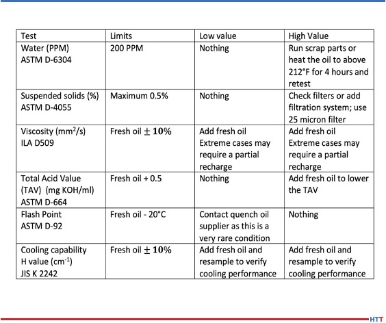
Over time the condition of a quench oil will change and corrective measures will be needed to bring the quench oil back into the suggested supplier’s operating parameters. The chart below helps understand what some of the methods need to be.
With proper care and maintenance, a quench oil can last a very long time. A conventional oil should last 10 to 15 years or longer while a marquench oil should last seven to 10 years. The proper care of a quench is simple and straight forward. A quality quench oil should not need the use of additives to improve oxidation resistance or quench speed. Simply adding enough fresh virgin oil to replace the oil that is being dragged out through normal operations should replenish the oxidation protection and quench speed to within the normal operating parameters. The table below offers recommendations for treating out of normal operating parameters for the required CQI-9 tests.
Recommendations for treating out of normal operating parameters for the required CQI-9 tests
Most heat treaters make weekly quench oil additions to their quench tanks. The most popular type of filtration system is a kidney loop style where the quench oil is constantly filtered. There are two basic types of these systems. They differ in the number of filters used. For a single filter system, a 25 micron filter is sufficient for quench oil filtration. In a two-stage filtration system, a 50 micron filter is typically used in the first stage and a 25 micron filter is used in the second stage. In a two-stage filter, the cheaper 50 micron filter will be replaced more often than the 25 micron filter in the second stage.
Utilizing a compliant CQI-9 analysis and the supplier provided operating parameters for the CQI-9 required tests is the first step in the proper care of a quench oil. The next basic steps are ensuring there is enough fresh quench oil available for regular additions to replace the oil that is lost through drag out and proper filtration of the quench oil in a constant kidney loop type of a system. With these steps in place, a quench oil will offer consistent performance for years and will be one less concern heat treaters face in the operation of their furnaces.
References:
Automotive Industry Action Group, “CQI9 “Special Process: Heat Treatment System Assessment;” AIAG version 3, 10/2011.
M.A. Grossman and M. Asimov. Hardenability and Quenching. 1940 Iron Age Vol. 107 No.17 Pp 25-29.
About the Author:
Greg Steiger is the senior key account manager of Idemitsu Lubricants America for quench products. Previous to this position, Steiger served in a variety of technical service, research and development, and sales marketing roles for Chemtool, Inc., Witco Chemical Company, Inc., D.A. Stuart Company, and Safety-Kleen, Inc. He obtained a BSc in Chemistry from the University of Illinois at Chicago and is currently pursuing a Master’s Degree in Materials Engineering at Auburn University. He is also a member of ASM International.
What have we learned these past six months? Well, for starters, everyone misses being face-to-face! Yet many heat treaters have taken this time to be flexible and innovative, building their intellectual fitness, so to speak.
This article, a Heat Treat Today Original Content piece, highlights some of the major themes which digital opportunities provide to heat treaters. You may note that some of these opportunities are still being offered; please reference company websites to confirm.
“COVID-19 came along… [but] it forced me to look into other projects which may be even more interesting. And I decided to build my intellectual property.”
-Harb Nayar, president of TAT Technologies, LLC on Heat Treat Radio
[spacer color=”3366FF” icon=”fa-lightbulb-o”]
Signs of life pre-April 2020 seem to be coming back, though many people are still reckoning with the work constraints. This past quarter, and even into Q3, heat treaters have seen a remarkable initiative to make learning online available. Heat Treat Today did a select study* of what a few of the most recent, heat treat specific events had to offer. The results of the examination demonstrates trends in the types of themes which heat treaters can improve their “intellectual fitness.”
Summary
A few themes stick out as key content: the fundamentals, quality control, additive manufacturing (AM) and 3D printing, and maintenance concerns.
source: Heat Treat Today
These themes were made available to heat treaters in the form of three main presentations: session or lecture format; panel discussion; round table. All platforms engaged in some form of online sessions which colored more lecture/seminar styled with scholarly professionals to addresses given by industry leaders or technical insiders. Larger, lengthier events, such as Furnaces North America and SECO/WARWICK’s e-Seminar incorporated panel discussions in addition to single-speaker sessions. Truly unique was the announced “round table” access at the Ceramics Expo Connect’s session on September 24th, “How to Improve Your Ceramic Products Material Properties Through Raw Material Optimization?”
Within these structures, a few presenters took advantage of the digital opportunity to offer case studies and live demonstrations of certain methods and processes. At the e-Seminar, multiple opportunities for this included “Symptoms of a Burner Issue – How to Solve It” and “Revealing the Secret of Carburizing,” while Buehler’sWilson Hardness Days (WHD) event promises “live demonstrations of DiaMet software.” Only a few of the events examined offered the opportunity to submit questions before the presentation occurred. Many sessions in this online forum were pre-recorded well in advance, so this might contribute as to why soliciting questions before the presentations wasn’t as widespread.
Four Themes of 2020
The Fundamentals
This one is not surprising. “The Fundamentals” refers to any overview, back-to-the-basics type of session that hits major ideas in the industry which might refine practices, but does not challenge or recreate heat treating theory/practice. An example of this is the technical session on day one of the FNA: “The Importance and the Proper Way to Monitor Polymer Quenches” to be given by Keisuke Kuroda of Idemitsu Lubricants America.
Hubbard-Hall’s webinar on cleaning titled “Optimizing Cleaning in Heat Treat Processes” promised to cover “the influence of contaminations in different heat treatment applications,” something that may not be as exciting as nitrogen gas quenching, but is still essential to know. At WHD, the event notes that “Machine Calibration and Servicing” will be a guaranteed part of the webinar on hardness testing.
Quality Control
Not to be confused with “The Fundamentals,” this theme encapsulates topics about implementing new theory and improving or refining current practice.
At the Ceramics Expo Connect, a session on “Powering a Mobile Future: The Role of Ceramics in Taking Solid State Batteries from Theory to Practice and Improving Lithium Ion Models” demonstrated this theme. If you attend the e-Seminar, you may have heard the panel “Maintenance in the Age of Industrial 4.0 Description,” which also falls into this theme. At a more particular level, Buehler will introduce the new Rockwell Tester at their event.
Additive Manufacturing and 3D Printing
At the cutting edge of industry development, these young applications in the heat treat world have been getting a lot of attention, with other forward-thinking topics on the horizon as well (like IoT and Industry 4.0). Buzz a constant buzz of these processes were apparent, particularly in the FNA 2020 schedule.
One of the technical session at FNA 2020 will be given by Dan Herring, the Heat Treat Dr., titled “Will Additive Manufacturing Add or Take Away Heat Treating?” At the e-Seminar, “3D Printing—Revolution or Evolution” was the title of one provocative panel discussion.
Maintenance
This is another big theme, and rightly so: maintenance concerns can cause problems with the heat treating process which could result in poor results, or dangerous outcomes.
FNA 2020 will be dealing with maintenance questions a lot over the next few days. On a micro-scale, Hubbard Hall’s webinar will be addressing these questions: “How closed cleaning machines contribute to cost efficiency and sustainability” and “How companies overcome specific cleaning challenges.”
Other Themes
“Troubleshooting” and “adapting to COVID-19” also stood out as recurring themes, though many sessions were concerned with these in relation to quality and future planning. Additionally, “COVID-19” in particular was considered during multi-day events as it related to pivoting one’s business strategy whereas single-day events focused on topics which are periphery to COVID-19 like “supply-chain” and “future of heat treat.”
Ok, But Does This Mean Anything?
Heat treaters are adaptive, responding to changes. But beyond picking up the latest item on the block, heat treaters want to make sure that their operations are reliable and excellent, hence the heavy focus on “The Fundamentals” and “Quality Control.” Testing new ideas and refining maintenance strategies are implemented, but it seems that this is typically after heat treaters know that they are performing with excellence in their day-to-day.
Further information on these events can be found on the company websites.
*The study focused on five of the most well-publicized and widely circulated events in the heat treat industry in August and September of 2020. The study is not meant to be exhaustive, but rather a case study of trends which may serve to be indicative of larger trends in the heat treat industry.
Heat treaters have their processes down to a science, literally. But what factor can compromise your heat treated part, let alone possibly cause detrimental damage to your facility?
Greg Steiger Sr. Key Account Manager Idemitsu Lubricants America
Michelle Bennett Quality Assurance Sr. Coordinator Idemitsu Lubricants America
Heat TreatToday is pleased to present this original content article for today's Technical Tuesday. Greg Steiger, senior key account manager at Idemitsu Lubricants America, and Michelle Bennett, quality assurance senior coordinator at Idemitsu Lubricants America, describe water contamination in quench oil, the effects of this contamination, and how to test and safely remove the water from the quench oil.
Introduction
Water is an amazing substance. Water helped create the Grand Canyon and Niagara Falls. When water freezes, it doesn’t contract like most materials. Instead, it expands and creates potholes that swallow up our cars every winter. As the temperature rises, water also expands. This property allows water to heat our homes and is why steam engines work. The thermal expansion of water as it turns into steam is what can create catastrophic events in a quench oil. This paper will look at potential water contamination sources in a quench oil, what the effects of the water can be, how to test for the presence of water in a quench oil, and how to safely remove the water from a quench oil.
Sources of water contamination
There are two major classifications of potential water contamination. The first source can be classified as potential internal sources of water. These potential sources are typically a part of heat treating furnace or oil cooling system. They include water-cooled bearings, fans, doors or heat exchangers. These water-cooled components are under a contestant pressure and will eventually leak. Because the quench tank is usually below these sources of water, the water will eventually find its way into the quench tank. Water-cooled bearings and fans are located within the furnace and are often directly above the quench tank. While a water-cooled door is typically not directly above a quench tank, it is in close proximity to the quench tank. This proximity will allow leaking water to enter the quench tank. Heat exchangers are typically situated away from the furnace. However, in a water-cooled heat exchanger, the water is never more than the wall thickness of the cooling tubes away from the oil. Should a cooling tube form a leak, the water and quench oil would simply mix within the cooling stream and the quench oil water mixture would return to the quench tank.
"The greatest risk of external water contamination lies in preventable operator or maintenance mistakes, especially when the equipment is down and open for maintenance."
The second classification is external sources. These sources of water contamination are not part of the heat treating furnace. Examples of external sources can be further broken down into leaks and operator or maintenance personnel mistakes. Leaks typically include fire extinguishers and fire suppression systems leaks, leaking fire resistant hydraulic systems, atmosphere leaks, pneumatic cylinders and building leaks. To prevent the leak type of contamination, routine maintenance, like a daily “Gemba” walk to spot any leaks, is the best defense against water entering a quench oil through a leak. The greatest risk of external water contamination lies in preventable operator or maintenance mistakes, especially when the equipment is down and open for maintenance.
Quite often when a furnace undergoes repairs, the quench oil is pumped out into empty totes to be reused after the furnace repair is finished. There is nothing wrong with doing this if the totes are clean. However, there have been reports of heat treaters doing this without first inspecting the totes to ensure that they are clean and free of any type of contamination. There have also been instances when the totes were not properly sealed and then stored outside, thus allowing rain water to get into the quench oil. But, the potential to add an incorrect product to the quench tank is a preventable operator error.
How water affects a quench oil
As previously mentioned, water expands as it turns into steam. At 212°F, water has a density of 0.96g/cm3.1 One gallon of water occupies 0.14 ft3. At one degree above boiling the steam from the boiling water has increased to occupy 224 ft3 and a density of 0.0006 g/cm3. The thermal expansion rate of water is approximately 1600%. What this means is the single gallon of water that was in the quench oil before it turned into steam now has a volume approaching 1600 gallons. In order for the 1600 gallons of steam to escape from the quench tank, it must displace an equal amount of quench oil. With nowhere to go, this displaced oil will find hot spots and open flames to create a catastrophic event.
Quench severity
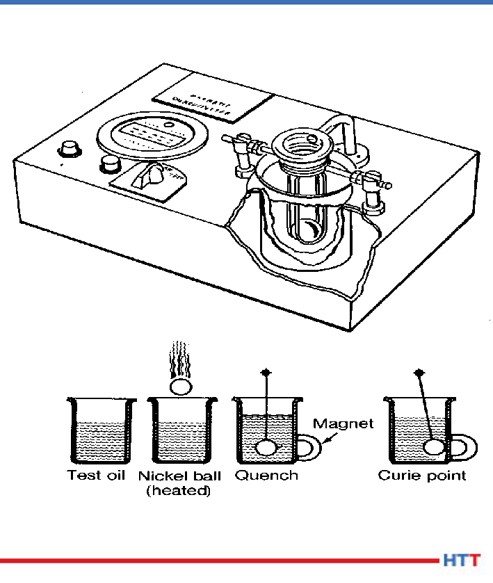
Fig.1 Schematic of ASTM D-3520 (ref. 7)
Historically, the severity of the quench has been measured by ASTM D-35202. In this method, a chromized nickel ball is heated to 885°C and is dropped through an electronic sensor, which starts a timer, and into a steel cylinder of quench oil in a magnetic field. Once the chromized nickel ball reaches the Currie temperature of nickel at 354°C, the ball becomes magnetic and closes the timing circuit when the ball comes into contact with the cylinder. The popularity of this test has always been that it provides a number that is easily interpreted by heat treaters to “rate” the oil as fast (9 – 11 seconds), “medium” (12 – 14 seconds), “slow” (15 – 20 seconds) or marquench (20 - 25 seconds). A schematic of the test method is shown in Figure #1.
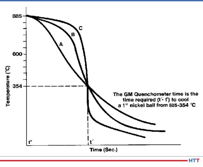
This test worked well to differentiate between different how well the quench oils cooled the nickel ball. The test really didn’t distinguish between the cooling characteristics of a quench oil. The test result in Figure #2show a time in seconds for the nickel ball to reach 354°C for three separate oils. However, when the actual cooling curves of the oils are examined there are three distinct cooling curves shown.
Fig. 2 Three separate cooling curves with the same quench speed as measured by ASTM D-3520 (ref. 7)
Because mechanical properties such as yield strength and hardness are dependent on the severity of the quench, the Grossman H value3 has become more popular over the years. In using the Grossman H value the lower the value the slower and less severe the quench. For instance air has an approximate H value of 0.01 cm-1 and water has an approximate H value of 0.4 cm-1. The calculation used to determine the Grossman H factor has historically been:
Where h is the heat transfer coefficient of the part when measured at the surface of the part and k is the thermal conductivity of the steel. Typically the heat transfer coefficient is measured at 705°C. A steel’s thermal conductivity does not typically change according to alloy composition or temperature. Therefore the Grossman H value is proportional to the heat transfer coefficient of the part.
Cooling curve
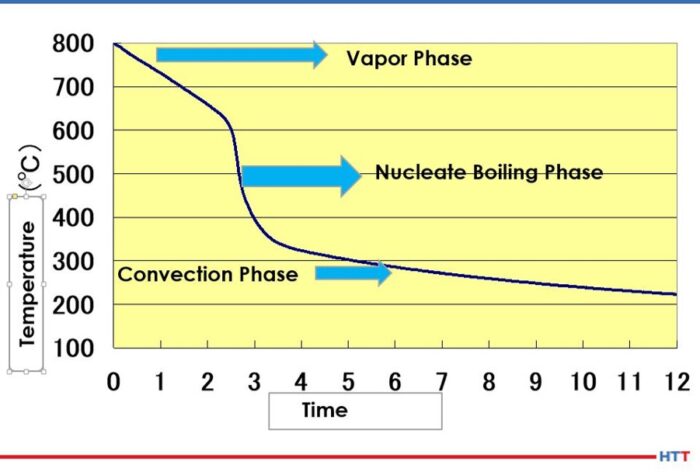
The basic cooling curve consists of three stages: the vapor blanket, nucleate boiling and convection. A basic cooling curve with the three different cooling phases is shown in Figure #3.
Fig.3 Three stage cooling curve (ref. 4)
In the vapor blanket stage, the load and the quench oil coming into contact with the load are above the evaporation temperature of the oil. An insulating vapor blanket forms around the load and no cooling occurs. Because the vapor blanket is insulating and does not allow for cooling, the vapor stage carries the highest risk of distortion.4 Once the vapor pressure decreases to a point where the oil can once again condense on the load and the temperature of the oil falls below the evaporation temperature, the nucleate boiling stage begins. In this stage, the load undergoes the most aggressive cooling. After sufficient cooling has occurred and the quench oil temperature is below the boiling temperature of the oil, a smooth transition into the convection stage begins.
Stabilization of the vapor stage
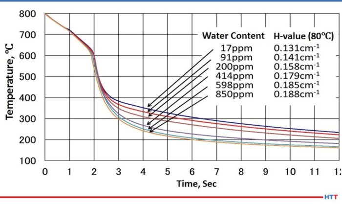
As water is dispersed throughout the oil, the viscosity of the oil changes. As the amount of water increases, the viscosity of the oil also increases.5 A careful examination of Figure #4 will also show a slight movement of the cooling curve to the left and a lengthening of the vapor stage as the amount of water increases. Furthermore the water in the oil is not uniformly dispersed, and this non-uniform dispersion creates uneven cooling rates throughout the oil. To restore even cooling, it is recommended the water in the quench oil be reduced to below 200 PPM.
Fig. 4 Cooling curve change due to water contamination (ref. 4)
Types of water found in a quench oil
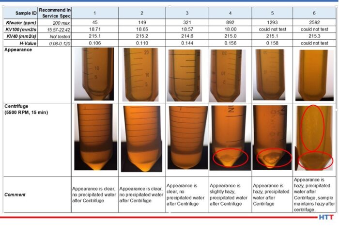
In simplistic terms, water in a quench oil can be thought of as being dispersed in the quench oil due to agitation or as free water having exceeded the saturation point of the oil. As a general rule of thumb in the industry, the saturation point is considered to be 0.1% or 1,000 PPM. However, the saturation point will vary according to the temperature of the oil and the additives within the quench oil. Daphne Hi Temp A-U is a good example of a clear amber quench oil. Figure #5 shows a picture array of the appearance of the oil as the amount of water approaches and then exceeds the 1000 PPM industry standard.
Fig. 5 Daphne Hi Temp A-U appearance as the amount of water dispersed within the oil nears and exceeds the saturation point of the oil. (Used with permission Idemitsu Lubricants America)
Notice in the data above that as the amount of water increases in the Daphne Hi Temp A-U, so does the viscosity as measured at 100°C. In addition to the viscosity rising as the amount of dispersed water increases, so also does the quench severity as measured by the Grossman H value. Furthermore, the appearance of the quench oil changes as the amount of water increases as well. (See Fig. 5 for the Daphne Hi Temp A-U.) With small amounts of dispersed water—45 PPM—the quench oil is clear and there is no water that is precipitated out after centrifuging for 15 minutes at 5500 RPM. However, as the amount of water begins to approach the 1000 PPM level, the appearance of the quench oil begins to become hazy. As the saturation point is exceeded, the appearance remains hazy and water precipitates out after centrifuging for 15 minutes at 5500 RPM.
Testing for oil in a quench oil
There are two basic types of testing methods for determining if there is water dispersed in a quench oil. One of the methods is subjective and the other is quantitative. The crackle test involves heating a metal coupon to approximately 400°F and placing a few drops of the quench oil on the surface. If there is a sufficient amount of water in the oil visible bubbling within the oil and audible crackling will occur. Unfortunately, this is typically above the saturation point of the quench oil. At which point it is often too late. Figure #6 shows examples of crackle testing.
Fig. 6 Crackle test results for Daphne Hi Temp A-U
The second and preferred testing method is through ASTM D-6304 Standard Test Method for Determination of Water in Petroleum Products, Lubricating Oils and Additives by Coulometric Karl Fisher Titration6. The Karl Fisher test uses the Bunsen electrochemical reaction to calculate the amount of water in a used oil and is accurate in used oil from 1 PPM to 50,000 PPM.
Removing water from a quench oil
Removing excessive water from a quench oil can be achieved economically through several methods. Table #1 is a brief trouble shooting guide to the safe removal of water from a quench oil.
Table 1 Trouble shooting guide for removal of water from a quench oil
Conclusion
Finding small amounts of water, less than 50 PPM is very common in a used quench oil sample. This small amount could simply be condensation within the bottle and quench tank. However,when the amount of water begins to reach levels above 200 PPM, troubles can begin. At levels above 200 PPM of water, the following may occur:
Uneven cooling due to non-uniform dispersing of the water within the quench oil
Increase in viscosity
Increase in Grossman H Value
Lengthening of the vapor blanket stage
Increase in the severity of the quench
Like most materials, water expands as it changes from a liquid into a vapor. With a thermal expansion rate of 1600%, a gallon of water turns into considerable more steam. Therefore excessive water transitioning into steam in a quench oil creates safety concerns when the steam forces the quench oil from the tank. Examples of these safety concerns are:
Risk of harm and injury to plant personnel
Damage to furnaces and related equipment
Damage to the heat treat facility the surrounding plant and nearby buildings
Severe cases can result in a quench oil fire or a building fire
The importance of a “Gemba" walk should not be overlooked. Water can enter into quench oil systems through normal heat treating operations such as a leak in a water-cooled piece of equipment, others can be from preventable sources such as a building leak or other human error. No matter what the source is, if water is suspected in a quench oil, the quench tank should be sampled and tested before it is used.
References:
Handbook of Chemistry and Physics. 60th edition CRC Press, p. E-18.
ASTM International, “Standard Test Method for Standard Time of Heat Treating Fluids (Magnetic Quenchometer Method),” American Society for Standards and Materials.
M. A. Grossman and M. Asimov, “Hardenability and Quenching,” 1940, Iron Age Vol. 107 no.17, p. 25-29.
ASTM International, "ASTM D-6304 Standard Test Method for Determination of Water in Petroleum Products, Lubricating Oils and Additives Coulometric Karl Fischer Titration," West Conshohocken, ASTM International, 2016.
B. Lisic and G.E. Totten, "From GM Quenchometer Via Cooling Curve Analysis to Temperature Gradient Method," ASM Proceedings: Heat Treating, 18th Conference, 1998.
About the Authors:
Greg Steiger is the senior key account manager of Idemitsu Lubricants America for quench products. Previous to this position, Steiger served in a variety of technical service, research and development, and sales marketing roles for Chemtool, Inc., Witco Chemical Company, Inc., D.A. Stuart Company, and Safety-Kleen, Inc. He obtained a BSc in Chemistry from the University of Illinois at Chicago and is currently pursuing a Master’s Degree in Materials Engineering at Auburn University. He is also a member of ASM International.
Michelle Bennett is the quality assurance senior coordinator at Idemitsu Lubricants America, supervising the company's I-LAS used oil analysis program. Over the past 9 years, she has worked in the quality control lab and the research and development department. Her bachelor’s degree is in Chemistry from Indiana University.


 Find heat treating products and services when you search on Heat Treat Buyers Guide.com