Hardness Testing

How To Tell If You Really Have an Abrasion Problem

Understanding abrasion can be the key to extending the life of your refractory lining. The following article provided by Plibrico Company examines abrasion resistance, its role in choosing a refractory solution, and what factors to take into consideration when assessing counter-measures.


Refractory material is designed to be very durable, withstand extreme service conditions and defy mechanical abuse in many different types of thermal-processing operations. However, severe conditions that cause abrasion in the form of high levels of mechanical scraping and airborne particulate matter can challenge refractories, shortening their service lives. 

Abrasion resistance is one of the most critical and possibly the most misunderstood considerations when choosing a refractory solution. A clear understanding of what abrasion is and, perhaps more importantly, what it is not can prevent needless repair costs and lead to significant savings. This is especially important when evaluating refractory designs for a new application or when considering upgrades for an existing one. 

What Abrasion Is 

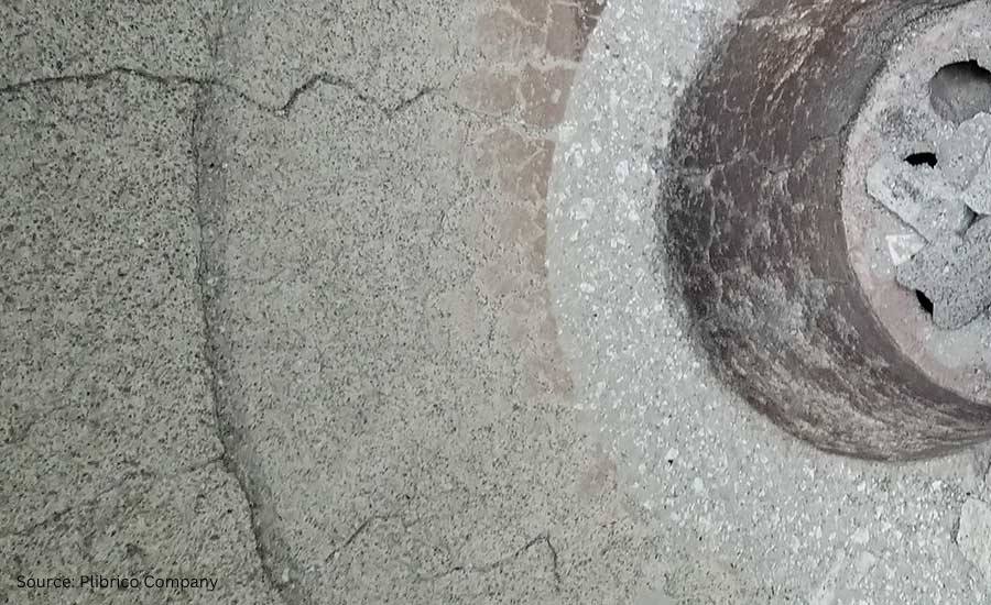
Abrasion is the destructive process that causes a material to wear away through mechanical scraping or scratching. Anyone who has ever grated cheese or sanded wood has experienced the abrasion encountered in everyday life. As abrasion continues, thin layers of the abraded material are removed, leaving the object thinner and usually making its surface smoother. 

The same process can be observed in the refractory world. Refractory linings are abraded by high-velocity airborne particulate, cleaning tools and fuel/process materials that pass through the unit and come into contact with the lining. The telltale sign of abrasion is a refractory lining that has steadily become thinner while its surface has become smoother. The surface may even shine as if it had just been polished, which is not surprising when we consider that polishing is another common form of abrasion. 

Fig. 1. Abrasion damage to the refractory bottom of a choke ring of a thermal-oxidizer unit

What Abrasion is Not 

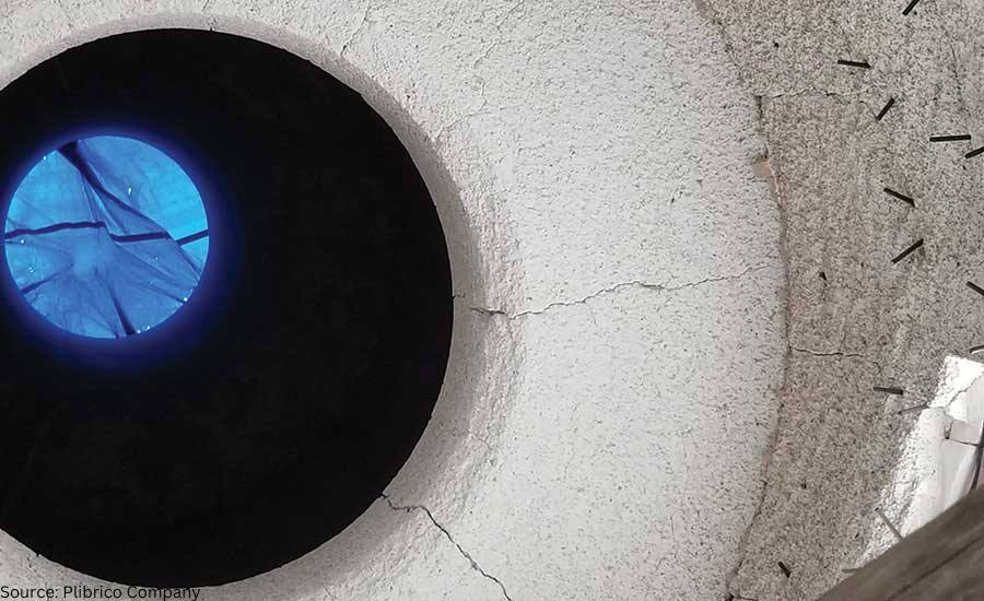
Abrasion is considered a type of mechanical abuse, but it is not the only type of mechanical abuse to which refractory linings are subjected. Equally common is impact: the sudden, forceful collision between the refractory lining and a moving object. Impact can come from a variety of sources. The moving object may be a cleaning tool, a piece of process material, a chunk of fuel or a dislodged mass of refractory or slag, depending on the application. Impact with such objects typically results in chips and cracks in the refractory lining. 

Refractory materials designed for abrasion resistance tend to have increased strength and hardness compared to those found in traditional refractories, and these abrasion-resistant materials may provide some resistance to impact. Abrasion-resistant properties can also lead to increased brittleness. This is because if the impact exceeds the strength of the material, chipping and cracking could potentially be worse than in traditional refractories. 

Compression and tension are also forms of mechanical abuse and can be caused by changes in the shape of the refractory lining as it is heated or cooled or by movements of the furnace shell itself – by intentional design or otherwise. Here again the increased strength and corresponding brittleness of the material could potentially result in a negative effect on the refractory lining. 

All types of mechanical abuse can cause thinning of the refractory lining, so it is important to conduct a detailed investigation into the destructive mechanism before drawing any conclusions. Refractory solutions designed to resist abrasion may not be helpful against damage caused by impact, compression or tension. 

Similarly, solutions designed to address other types of mechanical abuse may be ineffective against abrasion. For example, stainless steel needles are commonly incorporated into refractory linings to extend service life when impact resistance is required. The needles bridge cracks formed as a result of the impact, making it more difficult for these cracks to grow and connect. This helps the refractory lining hold together longer. The bridging provided by needles has no effect in an abrasion situation, however, since crack growth is not caused by the abrasion process. 

Meeting Abrasion-Resistance Demands 

Once abrasion is identified as the main mode of failure, there are several options to counter it. Selecting a refractory material based on a raw material hard enough to resist the abrasion is a common technique. For one material to abrade another it must be harder than the material being abraded. For instance, a diamond can be used to scratch glass, but glass cannot be used to scratch a diamond. 

It follows that refractory materials based on very hard raw materials, like silicon carbide, can be used to resist abrasion and extend the life of the lining. It should be remembered, however, that a refractory lining is made up of many different materials, not just the main constituent raw materials. Clay, cement, silica and other softer components will still be exposed and abraded even if abrasion of the main aggregate is stopped completely. 

Another option is to investigate the source of the abrasion and make adjustments to the process. Can a less-abrasive cleaning tool be used? Is there a way to limit the contact of the abrading process materials with the refractory lining? Is it possible to adjust the angle between the refractory lining and the incoming airborne particulate? 

A seemingly minor change in the process, with minimal cost and no downsides to the operation, can save in refractory replacement costs. When changes to the process are not an option, it is best to consider the abrasion resistance of the lining as a whole and select a specifically designed abrasion-resistant solution. A qualified, knowledgeable refractory solution expert with genuine experience will help you make the best decision for your specific application, taking into consideration the following: 

  • Speed of installation 
  • Service life 
  • All-in price 
Fig. 2. Airborne particle matter has contributed to the abrasion damage seen in the refractory of a thermal-oxidizer choke ring. Notice on the left side of the photo how the abrading of the refractory lining becomes worse.

Abrasion-Resistance Testing 

The most common measure of holistic abrasion resistance used to compare refractory solutions is the ASTM 704 test. This test exposes refractory lining materials to a stream of abrasive particulate that cause a portion of the sample to be abraded over time. By keeping sample size and shape constant – along with particle velocity, particle material and test duration – various refractory materials can be compared on an apples-to-apples basis. 

This testing can be performed by any qualified refractory testing lab and most reputable refractory manufacturers. Test results are recorded based on the volume of material lost from the sample during the test and are reported in cubic centimeters. Products with excellent abrasion resistance consistently test at 5 cc of loss or less, while elite materials can score less than 3 cc of loss. 

Products designed specifically for abrasion resistance will report ASTM 704 results on their material technical data sheets. It is important to remember that the abrasion-loss numbers reported on material technical data sheets are based on samples prepared in a lab under controlled conditions. Achieving these same properties in the field under real-world, job-site conditions would require a high-quality refractory installer partnered with a world-class refractory manufacturer. 

Fig. 3. Severe conditions lead to abrasion damage in the refractory lining of this dry-ash hopper. Notice the abrasion damage goes past the anchor line, leaving the bottom-left anchors exposed. 

Conclusion 

The thinning of a refractory lining due to abrasion is a source of frustration for many thermal-processing operations and is one of the most common modes of failure encountered in the refractory world. But, by taking the time to understand the failure mechanism and learn about the options available, you can realize significant savings by avoiding needless costs in the future. 

Learn more at www.plibrico.com

This article was initially published in Industrial Heating. All content here presented is original from the author.


How To Tell If You Really Have an Abrasion Problem Read More »

Manual Versus Automated Hardness Testing

When it comes to hardness testing nowadays, the process does not have to be done manually; automation has taken much of the burden away from operators. But which way produces the better result?

In this Heat Treat Today Original Content feature, Buehler recently published the results of a time study that compared case hardness testing of automotive crank pins and journals using both automation and manual testing. Find out which method showed a definite edge over the other in terms of time saved, less part manipulation, fewer errors in data transcription, and lower variability between performing tests.


EXECUTIVE SUMMARY

A study shows an operator time savings of 86% for making and measuring indents in three locations of crank pins and journals when using automation compared to manual testing. There was less part manipulation, fewer errors in data transcription and lower variability between operators performing tests.

INTRODUCTION

A large automotive manufacturer wanted to investigate the potential time savings of using automation for hardness testing crank pins and journals. Their existing process required two skilled operators per shift, two shifts per day, seven days per week. Tests were performed in three specified locations, two at forty-five degrees off axis and one perpendicular to the axis. Specified locations are critical, as missed locations could lead to manufactured parts being held in quarantine until further confirmation can be performed. Also of concern are failed parts that were inadvertently passed being installed and ultimately being prone to catastrophic failures. Data transcribing error was also a concern; if part information was entered incorrectly in a separate database it would cause mismatched data to lot number. When this occurs, it causes parts to become quarantined until the part information can be verified. With the total scrap cost being a considerable factor, skilled trained operators are needed for testing. Round robin testing is also used to determine the variability between operators. Qualifying new lines put into production increased testing by a factor of three to five times the normal operation analysis rate.

OBSERVATION

Current Process Observation

An evaluation of time to make and measure Vickers indentations on automotive crank pins and journals was established to determine a baseline of time for the existing process. Testing was done on a standalone manual system and required operator time for alignment, making and measuring of indents. The operators would fixture parts in similar orientation to ensure that measurements of the forty-five degree axis were in close proximity to expedite testing and reduce errors in testing. A high degree of manipulation for part alignment is necessary prior to physical testing to ensure accuracy.

It was observed that the operators’ set up time for location took the largest amount of testing time at 60%, measuring indents taking the second largest amount of time at 30% and making indents the third largest amount at 10%. The total amount of indents per pin and journal varied but averaged eighteen indents per section; six in each location. Total amount of indents for a crankshaft, pins being measured top dead center and bottom dead center and journals being measured along split, was 216 indents on average. The total analysis time for making and measuring indents at the specified locations on a crank was nine hours with 8 hours of operator interaction.

Implemented Process

For the implemented process a Wilson VH3100 series Vickers Microhardness Tester with DiaMet software was used. Parts were clamped in a machinist vice and placed on the stage without manipulation of orientation.

Figure 1.1 – Crank pin held in machinist vice (source: Buehler)

Trace function was used with the overview camera to create a template of the part to be tested; minimizing the set up time for the indent locations. The use of the template reduced the location set up time to 45 seconds in the three areas; two at forty-five degrees and one perpendicular to case.

Figure 1.2 – Trace function template for ease of indent locations (source: Buehler)

The DiaMet software snapped the template to the part at the specified location and the operators confirmed location. Observation of the set up time, making and measuring indents was 10, 50 and 40 percent respectively. Total amount of indents for a crankshaft was 216 indents on average with of time 1.25 hours with 15 minutes of operator interaction.

Figure 1.3 – Indent make and measure being performed automatically (source: Buehler)

Visual high and low threshold warnings were added to each program giving the operator the ability for quick assessment of parts versus the confirmation after all crank pins and journals were analyzed as it was in previous methodology.

Figure 1.4 – Visual high low threshold warnings to alert operators of
hardness thresholds (source: Buehler)

For reporting, metadata was set up to prevent operator errors in transcribing data.

Figure 1.5 – Metadata setup to reduce operator input transcription
errors (source: Buehler)

SUMMARY

The time study evaluation shows automation saves a significant amount of time with setup as well as the time required to make and measure the Vickers indents. The total amount of time that the operators spend setting the indent profile, measuring and compiling data is reduced by 86% as well as avoiding any errors in transcribing data. Repeatability of testing is increased operator to operator, as variability between operator judgement is eliminated. The combination of using trace function and templates eliminated the need for operators to spend time aligning parts on the stage as well as mitigated the risk of a misplaced indent profile. The increase of visibility of part failure is evident at time of measurement and gives the operator the ability to recheck either an area or total part without the need for extended quarantine of parts for re-examination. Using metadata fields within the Vickers testing program removed transcribing issues which would hold up batches of cranks until records could be reviewed.

(source: Buehler)

Manual Versus Automated Hardness Testing Read More »

Heat Treater Performs Brinell Hardness Testing with Precision for Primes

The largest subcontract heat treater of aluminum alloys in the UK, accredited to process components to Prime specifications, turned to a manufacturer of Brinell hardness testing machines to develop a more efficient testing process.

Foundrax BRINtronic automatic Brinell microscope

Alloy Heat Treatment (AHT), which serves the aerospace, automotive, energy, and other sectors, has a large number of prime customer approvals including Leonardo Helicopters, Airbus, Safran, Boeing, and BAE Systems. They are accredited to heat treat to these Prime’s specifications and often work as a trusted supplier to other companies that deal directly with them. Part of the Prime specifications dictates that Brinell hardness testing is carried out prior to releasing the components. AHT settled on the Foundrax BRINtronic automatic Brinell microscope, designed by Foundrax Engineering Products, based in Wessex, England.

“Part of the release process for aluminum alloys is that we must do conductivity and hardness testing on every job that leaves us,” said Steve Roberts, Quality Director with Alloy Heat Treatment. “As such we were looking at ways that we could gain efficiencies in this process. Using the BRINtronic from Foundrax has allowed us to gain these efficiencies.”

Brinell hardness measurements were required to be taken in areas of components where access is limited by intricate machine webbing or where the nose diameter of the microscope is restricted to approximately 30mm.

Alex Austin, Managing Director, Foundrax

“One of the problems we needed to solve with equipment selection is that the microscope must get into quite intricate places,” continued Roberts. “All the other microscopes we looked at have wide noses on them so, the design of the Foundrax scope was right up our street. We’ve used the manual Foundrax microscopes for as long as I’ve been here.”

“As the microscope automatically measures the indentation at multiple points, results are instant,” said Alex Austin, Managing Director of Foundrax. “They are recorded, and of course, the operator doesn’t have to turn the microscope 90 degrees and remeasure as he would with manual measurement. There is well over a 50% saving on measuring time.”

Foundrax BRINtronic display

“Obviously, the usability of the BRINtronic suited us,” said Roberts, “because we could get it into the places that we would struggle with using the competitor’s equipment. The process of measuring was far easier with the Foundrax BRINtronic as with the others we had to try and hold it with both hands and press buttons. They weren’t particularly well balanced either so in practice we were losing efficiencies rather than gaining them.”


Main photo caption: Steve Roberts of AHT uses the BRINtronic testing machine from Foundrax.

Heat Treater Performs Brinell Hardness Testing with Precision for Primes Read More »

Sacrificial Lambs: Hardness Testing and Heat Treating


Source: Gear Technology


Charles D. Schultz, president of Beyta Gear Service

In a recent blog post at Gear Technology, Charles D. Schultz, president of Beyta Gear Service, addressed the importance of accuracy when describing hardness test location and the reason why “sacrificial lambs” are needed during production.

“I cannot emphasize enough that if you are not cutting up parts or coupons you do not know what is really happening during your thermal processing.” ~ Charles D. Schulz


Read more: “Gear Materials: More Inside Heat Treating Trivia”

Photo Credit: Gear Technology

Sacrificial Lambs: Hardness Testing and Heat Treating Read More »

Tackling the Hard-ness of Hardness Testing


Source: Struers.com


Hardness testing in heat treating has evolved to a precision science necessary to provide reliability in resolving yield strength of metal materials and to assist in comparing property differences of two materials, ultimately determining “the success or failure of a particular heat-treatment operation” (Daniel Herring, “Common Pitfalls in Hardness Testing,” Gear Solutions Magazine).

According to Herring, “The Heat Treat Doctor®” (see his Heat Treat Today consultant’s page here), “Hardness testing is thought to be one of the easiest tests to perform on the shop floor or in the metallurgical laboratory, but it can be one of the hardest tests to do properly.”

Today’s Best of the Web feature offers an easy-to-follow primer on this hard testing process, providing the following:

  • Definition of Hardness Testing
  • How Hardness Tests Work
  • Selecting the Best Hardness Test Method
  • The Four Most Common Indentation Hardness Tests: their uses, suitability, and distinctives
  • How to Ensure Accuracy and Repeatability in Hardness Testing
  • Surface Preparation Requirements for Hardness Testing
  • Definition of Hardness Testing Loads
  • Indent Spacing
  • Troubleshooting for Hardness Tests

For a teaser, consider this excerpt from the article from Struers:

Factors that influence hardness testing

A number of factors influence hardness tests results. As a general rule, the lower the load you use in the hardness test, the more factors that need to be controlled to ensure an accurate conclusion of the hardness test. 

Here are a few of the most important factors to consider to ensure an accurate conclusion from a hardness test.

  • External factors such as light, dirt, vibrations, temperature, and humidity should be controlled
  • The tester and stage should be secured on a solid horizontal table, and the sample should be clamped or held in a holder or anvil
  • The indenter should be perpendicular to the tested surface
  • Illumination settings should be constant during the test when using Vickers, Knoop, or Brinell
  • The tester should be recalibrated/verified every time you change the indenter or objective lens


Read more: “Hardness Testing Is a Key Element in Many Quality Control Procedures and R&D Work”

Photo credit: Struers

Tackling the Hard-ness of Hardness Testing Read More »