A Welcome Diversion: Smart Pump System Revolution for Self-Cleaning Furnaces
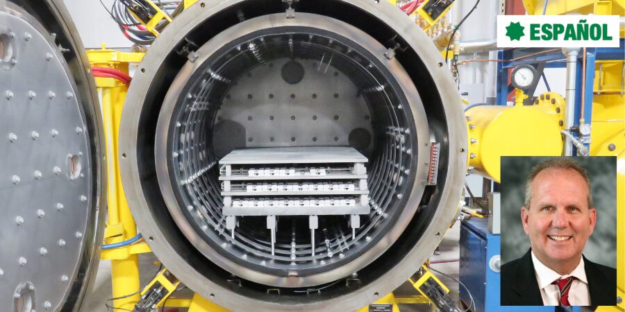
What if your vacuum furnace could clean itself? In this Technical Tuesday installment, Bob Hill, FASM, president of Solar Atmospheres of Western PA and Michigan, explores a revolutionary dual roughing pump configuration that eliminates the need for solvents, foil wrapping, and manual pre-cleaning.

This informative piece was first released in Heat Treat Today’s December 2025 Annual Medical & Energy Heat Treat print edition.
Para leer el artículo en español, haga clic aquí.
Introduction
Vacuum furnaces require an exceptionally clean environment to process critical components, from medical devices to aerospace. But laborious, time-consuming component cleaning to ensure purity of the furnace and parts does not necessarily need to be done by people. With the right pumps, your vacuum furnace can clean itself. Explore what a fully integrated, vacuum-based cleaning cycle could look like by leveraging an innovative dual roughing pump configuration.
In the vacuum heat treating world, where critical components are often near-net-shape with minimal to zero stock removal, the surface aesthetics of the final product are critical to the end user. Across industries like aerospace, medical devices, and power generation, vacuum processing has become increasingly valued — not only for its precision, but also for its ability to eliminate downstream operations, ultimately saving cost and time.
Given these benefits, clients are frequently willing to pay a premium for bright, clean work. To achieve these pristine results, vacuum heat treaters insist that incoming parts must be clean and oil-free. However, what qualifies as “clean” in a manufacturing environment rarely meets the exacting standards required for vacuum thermal processing. As a result, many commercial heat treaters adopt secondary cleaning measures to ensure part cleanliness and to protect their vacuum furnaces from contamination by machining oils, lubricants, Dykem, oxidation, or polishing compounds.

Pre-Heat Treatment Cleaning: Traditional Challenges
Before any vacuum heat treatment, components must be thoroughly cleaned to remove organic and inorganic contaminants. Common practices include solvent immersion, drying, and vapor degreasing. This cleaning step is designed to eliminate residues that can volatilize and redeposit within the vacuum furnace, potentially compromising part quality and damaging the vacuum furnace hot zone and cold wall.
However, commonly used cleaning agents are often flammable, toxic, environmentally regulated, and costly to dispose of when spent.
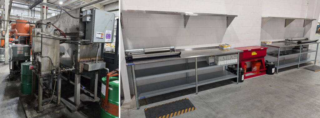
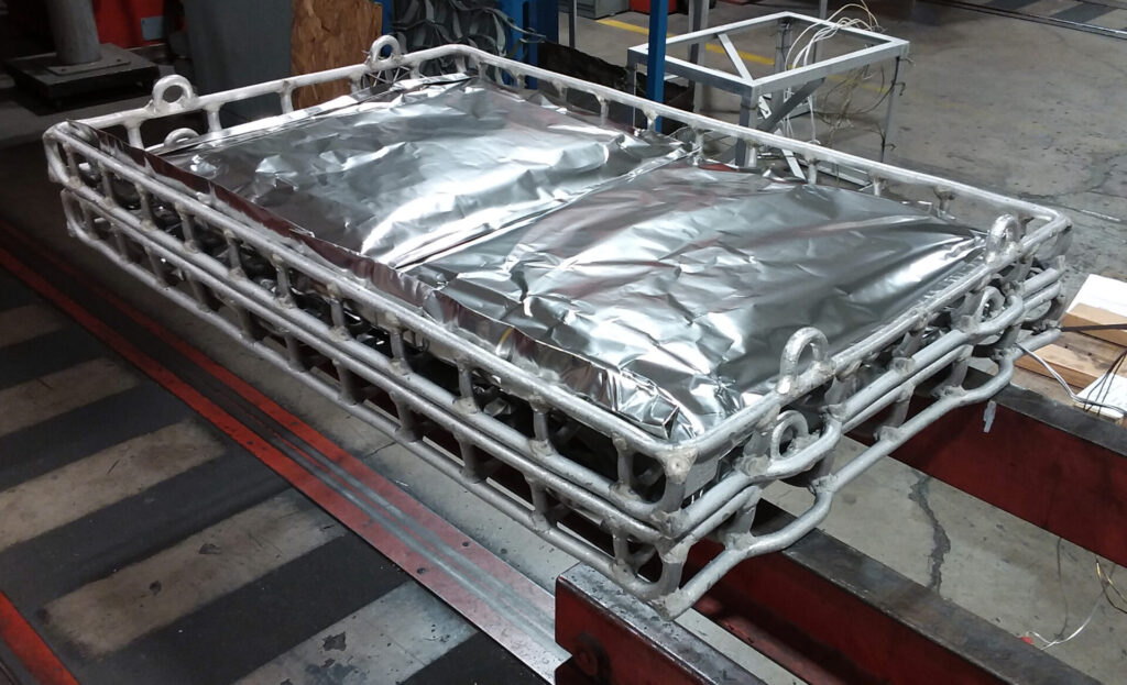
Given that commercial heat treaters process parts from thousands of upstream operations, each introducing its own set of contaminants, cross-contamination becomes a significant risk. Stainless steel foil wrapping is often used as a defensive measure, isolating parts from the furnace environment. While wrapping is often effective, it can be labor-intensive, expensive, and even potentially hazardous. Even with the proper PPE, the foil edges are razor-sharp. Foil wrapping continues to be a top health and safety concern for employees.
The MIM Furnace: A Catalyst for Innovation
Five years ago, Solar Atmospheres of Western Pennsylvania was tasked with sintering pre-sintered metal injection molding (MIM) parts at 2200°F. The binders present in these firearm parts volatilized during processing and heavily contaminated the vacuum furnace, resulting in extensive downtime and maintenance.
Instead of constructing a traditional “cold trap” to capture volatiles, CEO William Jones developed a more innovative solution: a “hot trap” designed to divert and capture contaminants before they could deposit inside the furnace. This proactive adaptation has proven to drastically improve part quality while eliminating the laborious and frequent cleaning of hot zones and cold walls.
After that MIM job ended, the underutilized furnace prompted experimentation. This adapted furnace proved to perform well on unwanted binders. So, we set out to test how this same system could be adapted to remove impurities from everyday production parts. After extensive trials using noncritical PH-grade stainless steel components, a fully integrated, vacuum-based cleaning and aging cycle was perfected. This development has since replaced traditional expensive pre-cleaning methods and dangerous foil wrapping, producing consistently clean and bright 17-4 PH aerospace components.
The Self-Cleaning Vacuum Furnace: How It Works
The key innovation lies in a dual roughing pump configuration.
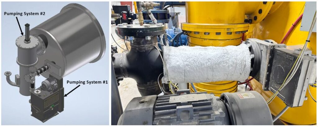
Source: Solar Atmospheres
Pumping System #1 — Initial Pump-Down and Contaminant Removal:
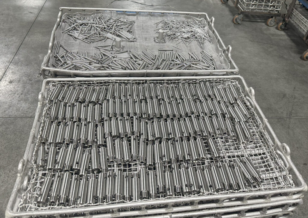
- Components are loaded into the furnace unwrapped and uncleaned.
- Only Roughing Pump #1 is activated during the initial pump-down.
- A slow temperature ramp allows contaminants to vaporize and exit the hot zone through a heated port into Pump #1.
- Contaminants are safely trapped in the pump’s oil — the “hot trap.”
Pumping System #2 — Transition to Heat Treatment:
- After off gassing is complete, Pump #1 is isolated.
- Pump #2 system, which includes a roughing pump, booster, diffusion, and holding pump, takes over.
- The chamber is then brought to 1 x 10⁻⁵ Torr and the standard vacuum thermal cycle proceeds.
This two-stage pumping sequence cleans both the parts and the chamber prior to heat treatment without ever opening the furnace door.
Results and Benefits
This newly developed vacuum furnace and process produces the following:
- Cleaner parts: Vacuum cleaning penetrates blind holes, threads, and keyways more effectively than traditional solvent or vapor degreasing methods.
- Injury reduction: The process eliminates the need for hazardous foil wrapping, significantly improving employee safety.
- Environmental and cost advantages: The process reduces or eliminates chemical solvent use, cuts labor associated with pre-cleaning and wrapping, and reduces hazardous waste and disposal costs.
- Furnace maintenance improvements: Hot zones and cold walls remain pristine — no weekly teardowns. Pump #1 oil is changed biweekly, eliminating roughing pump seizure concerns due to contaminated oil.
Conclusion: A Breakthrough in Vacuum Processing
Historically, part cleanliness in vacuum heat treating has been a persistent challenge — one often addressed through costly labor, chemicals, and dangerous stainless steel or titanium foil wrapping. Solar Atmospheres’ innovative dual-pump vacuum cleaning system, integrated seamlessly with a standard vacuum heat treatment cycle, redefines industry best practices.
This “self-cleaning furnace” concept not only delivers superior part finishes but also enhances safety, reduces environmental impact, and cuts operating costs. In a world where precision, cleanliness, and sustainability matter more than ever, this advancement may very well create a revolution in clean vacuum processing.
About The Author:

President
Solar Atmospheres of Western PA and Michigan
Source: Solar Atmospheres
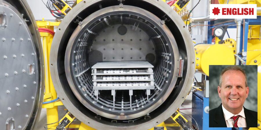
Bob Hill, FASM, president of Solar Atmospheres of Western PA and Michigan, began his career with Solar Atmospheres in 1995 at the headquarters plant located in Souderton, Pennsylvania. In 2000, Mr. Hill was assigned the responsibility of starting Solar Atmospheres’ second plant, Solar Atmospheres of Western PA, in Hermitage, Pennsylvania, where he has specialized in the development of large furnace technology and titanium processing capabilities. Additionally, he was awarded the prestigious Titanium Achievement Award in 2009 by the International Titanium Association. In 2022, Bob became president of his second plant, Solar Atmospheres of Michigan.
For more information: Contact Solar Atmospheres or visit www.solaratm.com.

A Welcome Diversion: Smart Pump System Revolution for Self-Cleaning Furnaces Read More »