Overcoming Quality Challenges for Automotive T6 Heat Treating
Three elements in the T6 aluminum heat treatment process — high temperature solution heat treatment, drastic temperature change in the water quench, and a long age hardening process — challenge accurate temperature monitoring. Thru-process technology gives in-house heat treaters the power to control these variables to overcome the unknowns. In the following Technical Tuesday article, Dr. Steve Offley, “Dr. O”, product marketing manager at PhoenixTM, examines the path forward through the challenges of aluminum heat treating.
This informative piece was first released in Heat Treat Today’s August 2024 Automotive print edition.
Aluminum Processing Growth
In today’s automotive and general manufacturing markets, aluminum is increasingly becoming the material of choice, being lighter, safer, and more sustainable. Manufacturers looking to replace existing materials with aluminum are needing new methodology to prove that thermal processing of aluminum parts and products is done to specification, efficiently and economically.
To add strength to pure aluminum, alloys are developed by the addition of elements dissolved into solid solutions employing the T6 heat treatment process (Figure 1). The alloy atoms create obstacles to dislocate movement of aluminum atoms through the aluminum matrix. This gives more structural integrity and strength.

Source: PhoenixTM
Process temperature control and uniformity is critical to the success of T6 heat treat to maximize the solubility of hardening solutes such as copper, magnesium, silicon, and zinc without exceeding the eutectic melting temperature. With a temperature difference of typically 9–15°F, knowing the accurate temperature of the product is essential. Control of the later quench process (Figure 1, Phase 3) is also critical not only to facilitate the alloy element precipitation phase but also to prevent unwanted part distortion/warping and risk of quench cracking.
T6 Process Monitoring Challenges
The T6 solution reheat process comes with many technical challenges where temperature profiling is concerned. The need to monitor all three of the equally important phases — solution treatment, quench, and the age hardening process — makes the trailing thermocouple methodology impossible.

Source: PhoenixTM
Even when considering applying thru-process temperature profiling technology, sending the data logger through the process, protected in a thermal barrier (Figure 2), the T6 heat treat process comes with significant challenges. A system will not only need to protect against heat (up to 1020°F) over a long process duration but also withstand the rigors of being plunged into a water quench. Rapid temperature transitions create elevated risk of distortion and warping which need to be addressed to give a reliable and robust monitoring solution.
Certain monitoring systems can provide protection to the data logger at 1022°F for up to 20 hours (Figure 3).

Thermal Protection Technology
To meet the challenges of the T6 heat treat process, the conventional thermal barrier design employing microporous insulation is replaced with a water tank design, with thermal protection using an evaporative phase change temperature control principle. Evaporative technology uses boiling water to keep the high temperature data logger (maximum operating temperature of 230°F) at a stable operating temperature of 212°F as the water changes phase from liquid to steam. The advantage of evaporative technology is that a physically smaller barrier is often possible. It is estimated that with a like for like size (volume) and weight, an evaporative barrier will provide in the region of twice the thermal protection of a standard thermal barrier with microporous insulation and heat sink. The level of thermal protection can be adjusted by changing the capacity of the water tank and the volume of water. Increasing the volume of water increases the duration at which the T6 temperature barrier will maintain the data logger temperature of 212°F before it is depleted by evaporation losses.
The TS06 thermal barrier design (Figure 4) incorporates a further level of protection with an outer layer of insulation blanket contained within a structural outer metal cage. The key role of this material is to act as an insulative layer around the water tank to reduce the risk of structural distortion from rapid temperature changes both positive and negative in the T6 process.

Source: PhoenixTM
Obviously, the evaporative loss rate of water is governed by the water tank geometry. A cube shaped tank will provide the best performance, but this may need to be adapted to meet process height restrictions. A TS06 thermal barrier with dimensions 8.5 x 18.6 x 25.2 inches (H x W x L) offering a water capacity of 3.5 US gallons provides 11 hours of protection at 1022°F. A larger TS06 with approximately twice the capacity 12.2 x 18.6 x 25.2 inches (H x W x L) and 7.7 US gallons gives approximately twice the protection (20 hours at 1022°F).
Innovative IP67 Sealing Design
Passing through the water quench, the data logger needs to be protected from water damage. This is achieved in the system design by combining a fully IP67 sealed data logger case and water tank front face plate through which the thermocouples exit. Traditionally in heat treatment applications, mineral insulated thermocouples are sealed using robust metal compression fittings. Although reliable, the compression seals are difficult to use, requiring long set-up times. The whole uncoiled straight cable length must be passed through the tight fitting which, for the 10 x 13 ft thermocouples, takes some patience. Thermocouples can be used and installed for multiple runs, if undamaged. Unfortunately, as the ferrule in the compression fitting bites into the MI cable, removal of the cable requires the thermocouple to be cut, preventing reuse.
To overcome the frustrations of compression fitting, an alternative innovative thermocouple sealing mechanism has been designed for use on the T6 thermal barrier (Figure 5).

Thermocouples can be slotted easily and quickly, tool free, into a precision cut rubber gasket without any need to uncoil the thermocouple completely. The rubber gasket has a unique bi-directional seal, allowing both sealing of each thermocouple but also sealing of the clamp face plate to the data logger tray, which is then secured to the water tank with a further silicone gasket seal. The new seal design allows thermocouples to be uninstalled and reused, reducing operating costs significantly.
Accurate Process Data considerations
The T6 applications come with a series of monitoring challenges which need to be considered carefully to guarantee the quality of the data obtained. Although the complete process time of the three phases can reach up to 10 hours, it is necessary to use a rapid sample interval (seconds) to provide a sufficient resolution. The data logger is designed to facilitate this with a minimum sample interval of 0.2 seconds over 20 channels and memory size of 3.8 million data points, allowing complete monitoring of the entire process. A sample interval of 0.2 seconds provides sufficient data points on the rapid quench cooling curve. The high resolution allows full analysis and optimization of the quench rate to achieve required metallurgical transitions yet avoid distortion or quench cracking risks.
Employing the phased evaporation thermal barrier design, the high temperature data logger with maximum operating temperature of 230°F will operate safely at 212°F. During the profile run, the data logger internal temperature will increase from ambient temperature to 212°F. To allow the thermocouple to accurately record temperature, the data logger offers a sophisticated cold junction compensation method, correcting the thermocouple read out (hot junction) for anticipated internal data logger temperature changes.
Data logger and thermocouple calibration data covering the complete measurement range (not just a single designated temperature) can be used to create detailed correction factor files. Correction factors are calculated by interpolation between two known calibration points using the linear method as approved by CQI-9 and AMS2750G. This method ensures that all profile data is corrected to the highest possible accuracy.
Addressing Real-Time, Thru-Process Temperature Monitoring Challenges
For a process time as long as the T6, real-time monitoring capability is a significant benefit. The unique two-way RF telemetry system used on the PhoenixTM system helps address the technical challenges of the three separate stages of the process. The RF signal can be transmitted from the data logger through a series of routers linked back to the main coordinator connected to the monitoring PC. The wirelessly connected routers are located at convenient points in the process (solution treatment furnace, quench tank, aging furnace) to capture all live data without any inconvenience of routing communication cables.
A major challenge in the T6 process is the quench step from an RF telemetry perspective. An RF signal cannot escape from water in the quench tank. To overcome this limitation, a “catch up” feature is implemented. Once the system exits the quench and the RF signal is re-established, any previously missing data is retransmitted guaranteeing full process coverage.
Process Quality Assurance and Validation
In the automotive industry, many operations will be working to the CQI-9 special process heat treat system assessment accreditation. As defined by the pyrometry standard, operators need to validate the accuracy and uniformity of the furnace work zone by employing a temperature uniformity survey (TUS).
The thru-process monitoring principle allows for an efficient method by which the TUS can be performed employing a TUS frame to position a defined number of thermocouples over the specific working zone of the furnace (product basket). As defined in the standard with particular reference to application assessment process Table C (aluminum heat treating), the uniformity for both the solution heat treatment and aging furnace needs to be proven to satisfy ±10°F of the threshold temperature during the soak time.
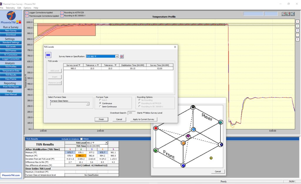
Complementing the TUS system, the Thermal View Survey software provides a means by which the full survey can be set up automatically allowing routine full analysis and reporting to the CQI-9 specification as shown in Figure 6.

Source: PhoenixTM
Interestingly, a significant further benefit of the thru-process principle is that by collecting process data for the whole process, many of the additional requirements of the process Table C can be achieved with reference to the quench. From the profile trace, key criteria such as quench media temperature, quench delay time, and quench cooling curve can be measured and reported with full traceability during the production run.
Summary
To fully understand, control, and optimize the T6 heat treat process, it is essential the entire process is monitored. Thru-process monitoring solutions, designed specifically, allow not only product temperature profiling of all the solution heat treatment, water quench, and age hardening phases, but also comprehensive temperature uniformity surveying to comply with CQI-9.
About the Author:

Dr. Steve Offley, “Dr. O,” has been the product marketing manager at PhoenixTM for the last five years after a career of over 25 years in temperature monitoring focusing on the heat treatment, paint, and general manufacturing industries. A key aspect of his role is the product management of the innovative PhoenixTM range of thru-process temperature and optical profiling and TUS monitoring system solutions.
For more information: Contact Steve at Steve.Offley@phoenixtm.com.
Find Heat Treating Products And Services When You Search On Heat Treat Buyers Guide.Com
Overcoming Quality Challenges for Automotive T6 Heat Treating Read More »


 Knowing the precise temperature from within your continuous heat treat process is now possible. In this


