MANUFACTURING HEAT TREAT

Dr. Valery Rudnev on Equipment Selection for Scan Hardening, Part 2

Dr. Valery Rudnev on . . . 

Induction Hardening Tips: Equipment Selection for Scan Hardening, Part 2

This is the second installment of a multi-part column on equipment selection for induction heat treatment. Part 1, Dr. Valery Rudnev On . . . Induction Hardening Tips: Equipment Selection for Scan Hardening, covered types of scanners, scan hardening system setup, quenching challenges, maximizing process flexibility, and computer modeling. In this installment, Dr. Valery Rudnev discusses another critical aspect of induction scan hardening: inductor design subtleties and a comparison of different fabrication techniques (brazing vs. CNC
machining vs. 3D printing).

Introduction

Hardening inductors are often considered the weakest link in an induc­tion hardening system because they may carry significant elec­trical power and operate in harsh environments exposed to high temperatures, water, and other coolants while being subjected to mechanical movement and potential sudden part con­tact.

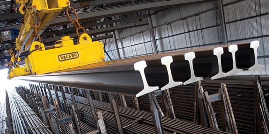
Single-turn or multiturn inductors may be used in scan hardening (Figure 1). Copper profiling and the number of turns is determined by the workpiece geometry, required hardness pattern, and the ability to properly load match the coil to the power supply without reaching the operational limits or by other specific process requirements, such as the production rate or the hardness pattern runout/pattern cutoff. [1]

Figure 1: Single-turn or multiturn inductors may be used in scan hardening.

The longer (in case of horizontal arrangement) or the higher (vertical arrangement) the scan coil is, the faster the scan rate can be. This is due to the simple fact that the longer inductor leads to a longer period when the part will be inside the coil; therefore, the scan rate can be greater. However, limitations on the maximum length of the inductor’s heating face may be associated with the maximum permissible runout.

Hardness Pattern Runout Control

Single-turn inductors with narrow heating faces (3mm-6mm wide) are used where a sharp pattern runout is needed. An example of this would be the case where a pattern must end near a snap ring groove. Inductors with wider heating faces or two-turn coils can be used when a faster scan rate is desired and an extended runout is permitted. The main disadvantage to the excessively wide heating face is that it may result in an unspecified shift of coil current density when hardening complex geometric parts due to an electromagnetic proximity effect. [1]

Inductor Fabrication Techniques

In applications where high process repeatability is critical (including automotive, aerospace, defense and other industries), the great majority of scan hardening inductors are CNC machined from a solid copper block, thus making them rigid, durable, and repeatable. CAD/CAM/CNC software pro­grams are created that provide appropriate cutter-to-copper spatial relationships, which produce inductors of the re­quired shape and precision regard­less of complexity. Figure 2 shows a variety of fin­ished and semi-finished CNC-machined hardening inductors. [2]

Figure 2: fin­ished and semi-finished CNC-machined hardening inductors

In other cases, copper tubing (square, rectangular, round, or die-formed shaped tubes) may be used for coil fabrication (Figure 3). Copper tubing is typically annealed to improve its ductility, bending properties, and workability. When sharp bends or complex coil shapes are required, inductor segments made from tubing are assembled by brazing. Joints are often overlapped, creating tongue-and-groove joints. Butt-joints should not be used.

Figure 3: Copper tubing (square, rectangular, round, or die-formed shaped tubes) may be used for coil fabrication.

A complex geometry inductor that contains numerous brazed joints, and elbow-type 90° joints in particular, could experience impeded water flow in the cooling coil turns, shortening coil life. Poor quality brazed joints are prime candidates for water leaks affecting not only the coil life expectancy but also a quality of hardened components due to a potential soft spotting in the areas of water leaks. Eliminating braze joints or dramatically reducing their number, particularly in current-carrying areas, is the key to fabricating durable, reliable, and long-last inductors.

Additive manufacturing (AM), or 3D printing, delivers successful fabrication of fixtures, tooling, holders, etc. Recently, some inductors have been fabricated using 3D printing as well. It is important to keep in mind that AM is not a single technology but it comprises a number of processes including direct metal laser sintering, electron beam melting, directed energy deposition, direct and indirect binder jetting, and others.

Depending upon a particular AM technique used in fabricating hardening inductors, it may face major challenges to match properties of pure copper. This includes (1) obtaining sufficiently high thermal conductivity (2) or low electrical resistivity, (3) ensuring high volumetric density, and (4) having minimum amount of residuals, just to name a few. All these factors affect coil life. Therefore, if you compare 3D printed inductors with brazed coils comprising numerous brazed joints, in the majority of cases, the life of 3D printed coils will surpass life of brazed inductors because of elimination of brazed joints in current-carrying regions. In addition, fabrication accuracy and repeatability of AM inductors typically surpasses the accuracy of brazed or bended coils.

The situation is different when comparing life of 3D printed coils vs. CNC machined inductors. Fabrication accuracy of both processes is very similar, however, in high-power density applications even small degradation of above discussed four factors associated with AM might become essential causing greater probability of stress-fatigue and stress-corrosion copper failure of 3D printed coils compared to CNC machined inductors fabricated from pure copper. Another factor to consider is repairability of 3D printed inductors. If you need to do a revision then it would be most likely required you to re-manufacture 3D printed coils. Regardless of a fabrication method and for quality assurance purposes, it is beneficial to apply computerized 3D metrology laser scanner technology (Figure 4) to verify coil dimensional accuracy and alignment precision after inductor fabrication and assembly.

Figure 4: It may be beneficial to apply computerized 3D metrology laser scanner technology to verify accuracy and alignment after inductor fabrication and assembly.

Material Selection

Copper and copper alloys are almost exclusively used to fabricate induction coils due to their reasonable cost, avail­ability, and a unique combination of electrical, thermal, and mechanical properties. Proper selection of copper grade and its purity is crucial to minimize the deleterious effects of factors that contribute to premature coil failure including stress-corrosion and stress-fatigue cracking, galvanic corro­sion, copper erosion, pitting, overheating, and work hardening. Cooling water pH also affects copper sus­ceptibility to cracking.

Oxygen-free high-conductivity (OFHC) copper should be specified for most hardening inductors. In addition to superior electrical and thermal properties, OFHC copper dramatically reduces the risk of hydrogen em­brittlement and developing localized “hot” and “cold” spots. The higher ductility of OFHC copper is also im­portant because coil turns are subjected to flexing due to electromagnetic forces. The higher cost of OFHC copper is offset by improved life expectancy of hardening inductor.

For scan inductors that are intended to heat fillets, an appropriate copper heating face region must be focused into the fillet area. Coil copper profiling and the use of flux concentrators (flux intensifiers) are beneficial to focus the magnetic field into the fillet. These applications require careful design because the induced current has a tendency to take the shortest path and stay in the shaft area rather than flowing into the fillet [1]. Therefore, all efforts must be made to focus the heat generation into the fillet. Typically, higher frequencies work better for this purpose.

Copper Wall Thickness

It is important to maintain sufficient wall thickness to carry the electrical currents. The wall thickness of an inductor’s heating face should increase as frequency decreases. This fact is directly related to both the current penetration depth in the copper δCu. [1] It is highly desirable for the current-carrying copper wall thickness to be 1.6 times greater than the δCu calculated at maximum working temperature. Increased kilowatt losses in the copper, which are associated with reduced coil electrical efficiency and greater water-cooling requirements, will occur if the wall is thinner than 1.6∙δCu.

The table below shows the variation of δCu vs. frequency at room temperature (20°C/68°F).

In some cases, the copper wall thickness can be noticeably thicker than the recommended value of 1.6∙δCu. This is because it may be mechanically impractical to use a tubing wall thickness of, for example, 0.25 mm (0.01 in.).

I recommend Reference #1 to readers interested in further discussion on design of hardening inductors.

References

  1. V.Rudnev, D.Loveless, R.Cook, Handbook of Induction Heating, 2nd Edition, CRC Press, 2017.
  2. V.Rudnev, A.Goodwin, S.Phillip, W.West, S.St.Pierre, Keys to Long-lasting Hardening Inductors: Experience, Materials and Precision, Advanced Materials & Processes, October, 2015, p.48-52.

______________________________________________

Dr. Valery Rudnev, FASM, is the Director of Science & Technology, Inductoheat Inc., and a co-author of Handbook of Induction Heating (2nd ed.), along with Don Loveless and Raymond L. Cook. The Handbook of Induction Heating, 2nd ed., is published by CRC Press. For more information click here.

Dr. Valery Rudnev on Equipment Selection for Scan Hardening, Part 2 Read More »

Gas Supplier, Process Controls Group Launch Heat Treatment Collaboration

A global provider of industrial furnace controls and process automation solutions announced a new collaboration with a leading industrial gas company that combines the core competencies of each company into a comprehensive offering for heat treatment customers. Praxair Inc is based in Danbury, Connecticut, and produces and distributes atmospheric, process, and specialty gases and high-performance surface coatings. Customers will have access to Praxair’s gases, application technologies, and supply systems, along with United Process Control Inc’s portfolio of specialized industrial flow measurement and atmosphere control products. This continues the long-standing relationship between Praxair and Atmosphere Engineering Company, now a member of UPC, based in West Chester, Ohio.

The combined capabilities of the two companies will bring more end-to-end technologies for a broad spectrum of batch and continuous heat-treating processes such as carburizing, carbonitriding, neutral hardening, annealing, gas quenching, and heat-treatment applications under vacuum processing.

“The automotive and aerospace industries continue to expand requirements for heat treating,” said Steve Mueller, Praxair’s Associate Director of Business Development for Metals and Materials Processing. “We have a team approach in place, combining Praxair’s process know-how and expertise in industrial gases with United Process Controls’ specialized products. Together we meet customers’ requirements for high-quality heat treating with reproducible standards in their furnace operations.”

“This strategic agreement with Praxair reflects our commitment to offer the heat-treating industry a complementary and evolving portfolio of innovative technologies that help drive process efficiency and reliability. We look forward to working closely with Praxair in the coming years, as we strive to further increase our presence in North America,” said Paul Oleszkiewicz, President, UPC.

Gas Supplier, Process Controls Group Launch Heat Treatment Collaboration Read More »

Rebar Micro Mill Planned in Florida

John Ferriola, Nucor chairman, CEO & president

The largest U.S. steel producer and “mini-mill” steelmaker recently announced plans to build a rebar micro mill near Frostproof, Florida, in a bid to capitalize on the growing demand for construction steel. The facility will produce steel rebar from scrap metal.

Charlotte-based Nucor Corporation will invest $240 million in the steel plant in Florida. The company began construction on its second rebar micro mill project in Sedalia, Missouri, in November 2017.

“Nucor has always focused on growing our business to better serve our customers. We are building this rebar micro mill in a great and growing market where demand is strong and there is currently an abundant supply of scrap, a good portion of which is handled by our scrap business,” said John Ferriola, chairman, CEO & president of Nucor Corporation. “Consistent with our planned strategy of being a low-cost producer, this micro mill will give us a cost advantage over our competitors who are shipping rebar into the region from long distances.”

The rebar micro mill, which will produce steel rebar from scrap metal, is expected to have an estimated annual capacity of 350,000 tons.

Dave Sumoski, executive vice president of Merchant and Rebar Products

“We would like to thank the many state and local officials, leaders, and partners who have assisted us with the project,” said Dave Sumoski, executive vice president of Merchant and Rebar Products. “Identifying the right location is an essential part of our rebar micro mill strategy, and this part of central Florida met all the criteria we evaluate. We look forward to becoming a member of the community.”


Rebar Micro Mill Planned in Florida Read More »

Endothermic Gas Generator Added to Brazilian Fastener Heat Treatment System

A major fastener manufacturer in South America recently received delivery of an endothermic gas generator intended for heat treatment operations at the company’s Brazilian plant.

Jomarca, a Brazilian producer of fasteners for the furniture, tooling, construction, and do-it-yourself markets, purchased the Atmosphere Engineering™ EndoFlex™ generator from United Process Controls (UPC) in reaction to doubled carburizing operations and increased production capacity. Carburizing operations now include ten large continuous rotary retort furnaces that process over 2200 US tons (2,000,000 kg) of fasteners a month.

The high-capacity generator was integrated into the plant’s existing gas distribution system in the first quarter of 2018 and is supplying endothermic gas to all carburizing furnaces. The EndoFlex operates at a lower cost and mixes to more accurate ratios, aimed at maintaining a constant furnace atmosphere and a consistent gas quality at all times. The enhanced control capabilities of the EndoFlex allow for continuous control and monitoring of CH4, dew point, differential pressure, gas temperature, and retort burnout, as well as data logging, which is critical for troubleshooting and meeting regulatory requirements.

Mr. Eric Jossart (Sales Director, UPC USA), Mr. João Marques Castelhano (President, Jomarca), and Marcio Torres Boragini (General Manager, UPC Brazil). In the background is an Atmosphere Engineering™ EndoFlex™ endothermic gas generator installed at Brazilian fastener manufacturer Jomarca

Endothermic Gas Generator Added to Brazilian Fastener Heat Treatment System Read More »

The Vacuum Sintering Furnace Examined

Andrea Alborghetti, Technical Manager of TAV Vacuum Furnaces


Source: TAV: The Vacuum Furnaces Blog

Following up on the first installment of his series on “perfect vacuum sintering” (linked here), Andrea Alborghetti, technical manager of TAV Vacuum Furnaces and contributor to the company’s blog, provides an overview of the right insulation for a vacuum sintering furnace, an examination of hot zone design, the distribution of gas-flow, and the box for loading and unloading.

Read more: “Perfect Vacuum Sintering Step by Step #2”

The Vacuum Sintering Furnace Examined Read More »

Four Vacuum Heat Treat Systems Shipped to Casting Company

Four vacuum furnaces were recently shipped to a major casting company in Arizona, three with a free work area of 54″ W x 41″ H x 72″ L and one with a free work area of 24″ W x 24″ H x 36″ L.

The supplier, G-M Enterprises, based in Corona, California, announced that all four are 2-bar furnaces with innovative hot zone design and construction. A 1200 gpm water cooling system was included in the installation.

Four Vacuum Heat Treat Systems Shipped to Casting Company Read More »

How Aging Heat Treatment of AF 1410 Steel Affects Impact Energy, Strength


Source: ASM International


ASM International recently posted an instructive article on the effect of aging temperature on impact energy and yield strength on AF 1410 steel, complete with a helpful graph displaying maximum and minimum results on both at various temperature ranges.

Read more: “Heat Treatment of High-Alloy Nickel-Cobalt Steels”

How Aging Heat Treatment of AF 1410 Steel Affects Impact Energy, Strength Read More »

Austempering Heat Treatment Expands into Arkansas

Steve Metz, Vice President of Sales and Marketing for Applied Products, Inc.

A Michigan-based company that specializes in austempering heat treatment technology recently announced expansion plans that will include a 51,000-square-foot heat treatment plant in Fort Smith, Arkansas.

The new location for Applied Process, Inc., will contain six furnaces and is expected to be fully operational in the 3rd quarter of 2018 to serve their customers in the automotive, agriculture, aerospace, heavy truck, railroad, mining sectors, as well as the military, throughout the Midwest and South. The company’s plants in Livonia, Michigan, and Oshkosh, Wisconsin, will remain in operation, the latter housing the world’s largest integral quench batch austempering furnace which is capable of austempering parts up to 20,000 lbs. in weight.

Rusty Rainbolt, plant manager, Applied Products, Inc., Fort Smith

“The additional capacity in Fort Smith will allow us to continue to offer industry-leading levels of customer service, quality and turn time,” said Steve Metz, Vice President of Sales and Marketing for Applied Process, Inc.. “The new facility will allow us to expand into new markets and serve a broader geographic customer base.”

Rusty Rainbolt, who has been with Applied Process for three years on the sales team, will be plant manager at the Fort Smith site.


Austempering Heat Treatment Expands into Arkansas Read More »

Heat Treat Basics: Scale Removal or Prevention?

Source: Paulo


Leading commercial heat treat company, Paulo, provides an excellent primer on heat treat scale, what causes it, and what to consider when determining whether to remove it or prevent it.

From the article: “Manufacturers and heat treaters each have methods at their disposal to deal with scale problems, but tradeoffs exist that depend a great deal on part makeup, specified heat treatment and what happens next with a given part.”

Read more: “Heat Treat Scale Removal and Prevention”

Heat Treat Basics: Scale Removal or Prevention? Read More »

Presidents’ Day Quiz: What Do Honest Abe and Heat Treating Have in Common?


Source: Total Materia


In honor of Presidents' Day, Heat Treat Today takes a cue from the U.S. penny, where we find embossed on the copper coin the image of one of the two U.S. presidents celebrated on this day, President Abraham Lincoln (16th). The link below will lead you to an article on the basics of heat treating copper and copper alloys; their end products, including wire and cable, sheet, strip, plate, rod, bars, tubing, forgings, castings, and powder metallurgy shapes; and the purposes for heat treating these metals, such as homogenizing, annealing, stress relieving, and precipitation hardening.

Read more: "Heat Treating of Copper and Copper Alloys"

Presidents’ Day Quiz: What Do Honest Abe and Heat Treating Have in Common? Read More »