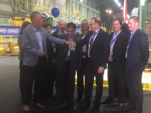
Hamilton, Ontario, mayor Mayor Fred Eisenberger greets Stelco officials at the ribbon cutting ceremony for the company’s new $30 million batch annealing facility. (Photo credit: Ken Mann, GlobalNews.ca)
An integrated and independent steelmaker based in Ontario, Canada, recently celebrated the opening of its new $30 million dollar batch annealing facility with a ribbon-cutting ceremony.
Stelco opened the plant in Hamilton, Ontario, earlier in the summer as a part of the company’s focus on investment in new technology and expansion of its production of flat-rolled value-added steels, including premium-quality coated, cold-rolled and hot-rolled steel products for the automotive, construction, and appliance industries. The restart of a modernized and upgraded temper mill, along with the installation of new annealing furnaces, will allow Stelco to add a full range of up to 200,000 net tons of fully processed cold-rolled steel to its product mix.
Main photo credit and caption: The Spec.com video (Youtube) / Alan Kestenbaum, Stelco executive chairman, at the ribbon-cutting
An industrial aluminum company headquartered in Atlanta, Georgia, recently received approval of its proposed acquisition of an Ohio-based aluminum rolled products producer, which would increase its capacity to provide lightweighting materials for the automotive market.
The European Commission announced approval for Novelis Inc. to acquire Aleris Corporation, conditioned upon the sale of Aleris’ plant in Duffel, Belgium, which produces aluminum for the automotive and specialties markets. Novelis is working expeditiously to market the plant to potential buyers, with the chosen counterparty and the definitive agreement for divestiture subject to European Commission approval.
With this conditional approval in the European Union, as well as a clear path forward for approval in the U.S., Novelis focuses on obtaining approval from the Chinese State Administration for Market Regulation (SAMR).
Steve Fisher, president and CEO, Novelis Inc
“Today’s announcement is another step forward in bringing Novelis and Aleris together, which will benefit our customers, employees, and the aluminum industry as a whole,” said Steve Fisher, president and CEO, Novelis Inc. “Overall, this transaction will strengthen our ability to compete against steel in the automotive market, meet growing customer demand for aluminum, achieve our recycling goals, and bolster our sustainability platform worldwide. In addition, it will further enhance our strategic position in Asia and diversify our overall product portfolio.”
The company expects to close the transaction by January 21, 2020, the outside date under the merger agreement.
A multinational automaker recently announced an investment of $391 million at its San Antonio truck assembly plant in response to customer demand and to expand multi-vehicle production capabilities by introducing various advanced manufacturing technologies.
Toyota’s announcement comes as part of a broader commitment from the company to invest $13 billion in its U.S. operations over five years through 2021. Toyota Texas also commits to continue funding local workforce development. As part of Toyota’s commitment to help San Antonio’s workforce and education, Alamo Promise will receive a $500,000 donation from Toyota Texas over a five-year period. Alamo Promise’s mission is to end poverty, enhance economic and social mobility and meet workforce demands throughout the city.
Separately, Aisin AW, a supplier to Toyota Texas and other automakers, announced that it will invest $400 million and bring 900 new jobs to a future facility in nearby Cibolo, TX.
Chris Reynolds, Toyota Motor North America chief administrative officer of manufacturing and corporate resources
“We’ve been in the U.S. for more than 60 years, creating a tremendous value chain in this country and creating an extensive footprint in the Alamo City since 2003,” said Chris Reynolds, Toyota Motor North America chief administrative officer of manufacturing and corporate resources. “With 10 U.S. plants, 1,500-strong dealer network, an extensive supply chain, and other operations, we directly and indirectly employ over 475,000 Americans and are committed to investing here.”
“The Lone Star State continues to build on its reputation as a manufacturing powerhouse thanks to investments from innovative companies like Toyota and Aisin AW,” said Governor Greg Abbott. “Their combined new investment of nearly $800 million in the San Antonio area is a testament to Texas’ unrivaled workforce and commitment to creating an environment where businesses can thrive free from the heavy hand of government regulation and over-taxation. I am grateful to Toyota and Aisin AW for bringing more jobs to the Lone Star State and I look forward to growing our already strong partnership.”
This is Toyota’s third investment at its San Antonio truck plant which assembles the full-size Tundra and mid-size Tacoma pickup trucks.
Conventional wisdom says that batch processing is for smaller volumes. Anytime large volumes of 1 million or more parts per year are envisioned, for instance with ferritic nitrocarburizing, the go-to technology is a roller hearth or other continuous systems like rotary retort or mesh belt furnace. In this article, which originally appeared in Heat Treat Today’sJune 2019 Automotive print edition, Mark Hemsath urges end-users and engineers who use, or specify, continuous systems to not undervalue automated batch processing for large volume production.
There are a number of trends in the automotive arena:
More parts are being light-weighted. This means they need more precise and repeatable heat treating.
Parts need to be cheaper and lighter. The trend we see are increased and more sophisticated stampings.
The trend is away from carbonitriding and toward ferritic nitrocarburizing due to less distortion on lighter parts.
Gears and such are smaller and require exact carburizing, minimized quench distortions, and less hard machining.
A deep discussion of all of these is beyond this article, but we will touch on each as we focus on nitrocarburizing for large-volume production.
Batch v. Continuous
What is the difference between a classic “batch” furnace and a classic “continuous” furnace? The answer is material handling. By definition, heat treating is a “batch” operation. In virtually all instances, the product must be brought to temperature and held—or “soaked”—for a specific time. Ferritic nitrocarburizing is no different. This ramp heat, hold, and cool is a “batch”. Thus, virtually all heat treating is batch and only material handling is the difference. The basic difference is that in batch we move the product in its cold state and heat it in one place (batch). In continuous furnaces, we move it while it is heating.
Advances in Material Handling
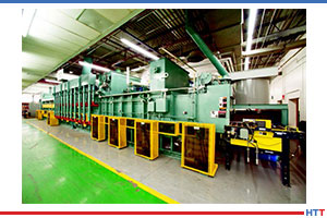
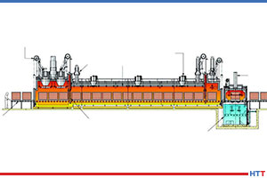
Figure 1: Roller hearth conveyor furnace with heating section, cooling tunnel and after cooling. Note the right angle turn via automatic conveyors to meet space requirements.
Advanced, fully automated, and reliable material handling has made great advances over the last two decades from more recent industries like Amazon, where millions of packages need to be moved through the shipping process, to older industries like heat treating which moves steel parts through furnaces and other equipment. Automation, such as conveyors with self-driven rollers and photo sensors or proximity switches, or robots and automated self-guided vehicles—all coordinated by a PLC—have made material handling more reliable. Manufacturers have a lot of options.
A continuous furnace like a roller convey-or—or “roller hearth”—furnace conveys the product while it is heating (Figures 1, 5 & 8). A mesh belt furnace conveys parts while heating, and a rotary retort furnace (Figure 4) moves parts via a heated rotating barrel to the next process step which is typically cooling or quenching. Moving parts while hot is a challenge, but reliable high volume heat treating is why these furnaces have seen such success over the years. Roller furnaces and rotary retort furnaces are still built and used in a wide variety of industries, and they make sense for a number of reasons. Lower energy use is one main factor.
With robots placing the load, both batch and continuous processes can be fully automated. With such options, batch processing has increased in use.
Automated Batch
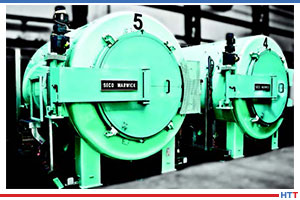
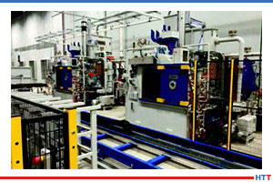
Figure 2: The doors have actuators for automatic opening.
A leading manufacturer of heat treating furnaces has implemented the high volume automation approach many times using batch technologies. In 2013, a fully automated batch FNC installation for gears was installed for processing 1 million gears annually.[1] As a result of this success, the customer added more batch furnaces to the line.
The furnaces in Figures 2 and 3 are retort-based nitriding and ferritic nitrocarburizing furnaces. With automatically opening doors, complete PLC control, and automated batch load movement, no humans are needed. A load car operates in both directions for a heavy load of two metric tons or more, allowing furnaces to be placed facing each other.
Automated, High-Volume System Design
Figure 3: This line consisted of pre-oxidizing ovens on one side to save time in the more expensive FNC furnaces. Cooling stations after heating are also added to reduce time in the batch furnace and make the parts safe for handling.
As mentioned, the company supplied nitrocarburizing technology using its ZeroFlow™ method (Figures 2 and 3) for an automated thermal treatment line for the production of a variety of gears. The line consisted of six large, front-loaded retort-style batch furnaces, a four-chamber vacuum washer, two ovens for pre-activation in air, additional post-cooling of the furnace charges, and an automatic robotic loader/unloader, which ensured charge transport within the system (seen in Figure 3). The automated line also included safety monitoring. System workload dimensions were 32″ wide x 32″ high x 60″ long with a gross workload capacity of 4,400 pounds. Production totaled 2,000 pounds of gears per hour. Good equipment design, retort technology, and use of ZeroFlow control technology resulted in a very successful project.
Cooling the Load and Vacuum Purging
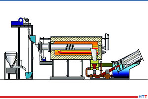
Figure 4: Whirl-Away Quench on a Rotary Retort line for small part efficient quenching/cooling.
There are advantages to continuous furnaces like a conventional roller hearth furnace; however, special options like fast cooling and vacuum purging present challenges to these conventional furnace designs. In batch, this is usually not a problem. Vacuum (and even cooling) is more difficult to attempt in continuous variations due to sealing challenges in the chamber designs. An example of a good solution is the rotary retort furnace shown in Figure 4, which offers single piece quenching where each piece falls into a water or oil quench and is “whirled-away,” a continuous furnace design which works well for small parts with a relatively small footprint. In batch, the whole load needs to be quenched together; this can present challenges that understanding the part needs and configurations can lead the process engineer to different solutions.
In a roller furnace, slow cooling means the furnace gets longer (Figure 1).
Variations in Continuous Batch – Semi-Continuous Processing
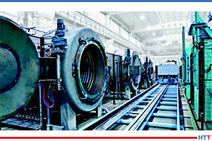
Figure 5: Hardening roller conveyor furnace with integral pre-heat and oil quench system
In Figure 6, an automated batch hardening line is shown. In Figure 7, the same process is shown, but with an added pre-heat chamber to allow faster processing via the pre-heat and use the single quench in a more productive manner. An oil quench is an expensive piece of equipment. The cycles are also always much shorter for quenching than heating, so we want to maximize the use of the quench. In a pure batch system, you need one quench per furnace. In the semi-continuous approach, the quench is used more frequently and there is higher productivity per capital dollar invested. In a roller hearth or rotary retort installation, the quench can be properly sized to handle all of the heating production. In an installation using pure batch systems, there might be 3 to 6 quench tanks. In a fully continuous roller furnace, there would be one quench (see Figure 5).
Figure 6: This automated batch line is for low pressure carburizing and vacuum hardening, with oil quench, automated washer, and batch temper furnace. The smart loader makes the cell fully automated.
Case History and Take-Aways
The automated batch system referred to in Figures 2 and 3 went online in 2014 and is currently operating at full capacity, while meeting the stringent requirements of the automotive industry. It achieved the planned production goal of 1 million gears per year with 99% process reliability and 98% equipment availability. The customer previously had a continuous conventional pusher furnace. The new line achieved an 80% reduction in the consumption of ammonia from that consumed using in the pusher furnace to nitrocarburize. Endothermic gas was also eliminated by the supply of a new methanol CO generator as the carbon source in the process.[1]
Figure 7: Triple chamber vacuum hardening line with oil quench and pre-heat chamber. Tray flow is right to left.
The take-away from this successful project is that in order to increase production even more, automated batch systems need to exhibit two factors to compete with a continuous system like a roller hearth furnace. First, the loads need to be optimized and very densely packed. Second, the batch loads need to be larger than the continuous loads. A standard size of 40″ x 40″ x 60″ has since been created which has 50% more volume than the unit in the example above. Making the furnace a bit larger is not that difficult. Additionally, in a recent application, CFC tooling has been utilized to assure more dense loading geometry with much lighter parts, giving reliable rack geometry for a load of 1,000 pieces.
Gas Usage – Benefit Batch
Figure 8: Cooling tunnel and exit of continuous roller hearth furnace for instrument transformer electrical steels annealing.
The biggest advantage of batch furnaces is the lower process gas usage. In continuous furnaces, in order to keep the process safe and clean, pressure must be maintained by flowing a significant volume of gases. With the constant opening of doors during the process and the need to keep operating pressures high enough to prevent air infiltration, atmosphere gas usage is always high. To keep the costs down, gases are typically generated with the use of an endothermic generator (40% Nitrogen, 40% Hydrogen, and 20% CO) or a lean exothermic generator with a low dewpoint. In all instances, the generator is another piece of thermal equipment to maintain and purchase.
Energy Costs – Benefit Continuous
In most instances, batch processing uses more energy—or more expensive energy—such as electricity. Electricity costs can vary tremendously from location to location whereas natural gas prices are more consistent and lower. Batch nitriding furnaces are available in gas-fired heating options at an added capital cost. However, the batch process still uses more energy per pound. If electricity is available at a reasonable rate, then the difference is not as great on a per pound basis. In a recent analysis, it was estimated that an electrically heated batch system came to cost the equivalent of about $0.06 per pound of FNC operating costs, versus $0.03 per pound of FNC operating costs in a continuous gas-fired variation (energy and consumables only).
Summary
Batch or continuous in large volume scenarios is no longer a clear-cut answer. Your heat treating professional and your furnace suppliers should understand this. There are literally dozens of variables that need to be assessed, and only after a careful analysis tailored for each customer can an optimized solution be designed with either batch or continuous furnace solutions.
Notes
1. Hemsath et al, “Nitrocarburizing Gears using the ZeroFlow Method in Large-Volume Production”, Thermal Processing, 10/2015
About the Author: Mark Hemsath is Director of Nitriding and Special Vacuum Furnaces at SECO/VACUUM Technologies, LLC and acting Thermal General Manager at SECO/WARWICK Corp. in Meadville, Pennsylvania. With 30 years of experience in the industrial furnace and heat treat equipment market, he is in charge of all North American atmosphere furnace sales, gas nitriding, and gas carburizing. This article originally appeared in Heat TreatToday’sJune 2019 Automotive print edition and is published here with the author’s permission.
A UK-based provider of hot form quench (HFQ®) technology recently joined forces with an auto parts manufacturer to bring HFQ® technology to the North American market.
ITL’s CEO, Jonathan Watkins
The creator of HFQ® technology, Impression Technologies Ltd (ITL), a leading advanced lightweighting solution for high-strength aluminum structures, has partnered with Telos Global in Caryville, Tennessee, with the latter taking on the production of high-strength aluminum body-in-white and chassis HFQ® components, enabling the company to service OEM requirements in the SUV, pick-up truck, and electric vehicle markets. Telos will manufacture HFQ® components at its facility in Caryville, Tennessee, before expanding into Asia and Europe.
Rick Teague, CEO and founder of Telos Global
“We are delighted to have entered this strategic partnership with Telos Global, which will offer automotive OEMs a high-volume supply base for stronger, lighter, more cost-effective structures made using HFQ® Technology to a guaranteed standard,” said ITL’s CEO, Jonathan Watkins. “We look forward to working with Telos to develop a global HFQ® supply chain capability in North America as well as globally.”
“This partnership with ITL offers Telos an exciting opportunity to supply automotive customers in North America and around the world with complex components manufactured from new, high-strength aluminum alloys,” said Rick Teague, CEO and founder of Telos Global. “We believe HFQ® Technology, using Telos’ scalable production system, will offer significant opportunities for light-weighting and design flexibility at a competitive price.”
A global aluminum rolling manufacturer recently reaffirmed its commitment to complete the acquisition of an Ohio-based aluminum rolled products producer, despite a U.S. Department of Justice (DOJ) lawsuit to block the transaction.
Novelis Inc. gave this statement regarding its proposed acquisition of Aleris Corporation, stating the company “intends to vigorously defend against the DOJ’s challenge”, believing it to be “without merit.”
The “acquisition will strengthen the aluminum industry’s ability to compete against steel in U.S. automotive body sheet market,” notes a release from Novelis.
Steve Fisher, President and CEO, Novelis Inc
“The DOJ lawsuit is based on the contention that the only relevant competition among automotive body sheet providers is that among aluminum manufacturers such as Novelis and Aleris. It ignores competition from steel automotive body sheet, even though steel automotive body sheet is currently used for nearly 90 percent of the market.”
“The day-to-day reality of the automotive body sheet market is aluminum automotive body sheet striving to take share from steel, and the steel automotive body sheet companies fighting back,” said Steve Fisher, president and CEO, Novelis Inc. “We are disappointed that the DOJ has missed this, but also confident that in the next phase of this process the full scope of the competition we face will be recognized appropriately. Our merger with Aleris threatens no one, and to the contrary will strengthen our ability to compete against steel, meet growing customer demand for aluminum, achieve our recycling goals, and bolster our sustainability platform worldwide.”
Assistant Attorney General Makan Delrahim of the Justice Department’s Antitrust Division
The Department of Justice filed the civil antitrust lawsuit seeking to block Novelis’s proposed acquisition of Aleris “in order to preserve competition in the North American market for rolled aluminum sheet for automotive applications.”
The Antitrust Division’s lawsuit alleges that the transaction would combine two of only four North American producers of aluminum auto body sheet.
“Automakers increasingly need aluminum auto body sheet to satisfy American consumers’ demand for larger vehicles that are lighter and more fuel-efficient. The loss of a competing supplier of aluminum auto body sheet ultimately would harm American car buyers,” said Assistant Attorney General Makan Delrahim of the Justice Department’s Antitrust Division.
The Antitrust Division has agreed with defendants to refer the matter to binding arbitration should certain conditions be triggered. The arbitration would resolve the issue of product market definition. This would mark the first time the Antitrust Division is using this arbitration authority to resolve a matter.
“This arbitration would allow the Antitrust Division to resolve the dispositive issue of market definition in this case efficiently and effectively, saving taxpayer resources,” said Delrahim. “Alternative dispute resolution is an important tool that the Antitrust Division can and will use, in appropriate circumstances, to maximize its enforcement resources to protect American consumers.”
According to legal analysts for corporate law firm Jones Day, “Most DOJ merger challenges have taken more than five months from filing of a complaint to a district court decision.”
“For this reason, the parties may have believed that pursuing arbitration on market definition—a topic that in traditional litigation can consume significant time for discovery and briefing—would provide them with deal certainty sooner than litigation. DOJ, in turn, may have viewed the decision as consistent with its larger policy goal of streamlining the merger review process.”
A Michigan-based heat treatment operation specializing in salt quenching and austempering recently announced that it has been acquired by a leading surface technology company.
Richard Wright, COO of the US Division of Aalberts Material Technology
In the 100% acquisition, Applied Process of Livonia, Michigan, will join the Material Technology group within Aalberts N.V. (Aalberts), a Dutch industrial technology company which operates in over 50 countries. The Material Technology group offers a unique combination of advanced heat and surface treatment technologies utilizing a global network of service locations with excellent local knowledge to customers active in general industries, automotive, aerospace and power generation.
Harold Karp, Applied Process president and CEO
“Aalberts is very excited that Applied Process is joining our team of world-class service providers,” said Richard Wright, COO of the US Division of Aalberts Material Technology. “Applied Process is the world-wide leader in austempering heat treatment, and we look forward to supporting their efforts to expand their technology and service offerings.”
“We are very excited to be part of the Aalberts family,” Harold Karp, Applied Process president and CEO. “We especially look forward to the synergistic opportunities of providing a broader and stronger service offering to our customers that will come from the technical expertise and other businesses within Aalberts.”
The Applied Process brand will continue on, as will the entire leadership team.
An international automotive corporation that designs, develops, and manufactures metal automotive components recently received a hot stamping furnace from a manufacturer of standard and custom industrial heat treat furnaces.
The Gestamp Research and Development facility, located in Auburn Hills, Michigan, added an electrically heated, four chamber hot stamping furnace built by Lindberg/MPH, an industrial thermal processor.
Bill St. Thomas Business Development Manager Lindberg/MPH
“This Lindberg/MPH hot stamping furnace provides uniform heating for a wide variety of high-strength steels or aluminum materials prior to hot stamping or hydro-forming applications. The team at Gestamp has been incredible to work with on this project and we are proud to be their supplier,” said Bill St. Thomas, Business Development Manager.
The furnace is integrated at the Gestamp facility with a robotic transfer system and hydraulic hot stamping press. The four chambers operate independently with the top chamber designated for aluminum treatment. This type of hot stamping system allows the customer the flexibility to treat different steels simultaneously and takes up a much smaller footprint than a continuous system.
The heat treating of constant tension bands used by automakers is a complex process, and the challenge posed to a leading heat treating company by a supplier of these bands was to determine how to reduce the risk of failure due to stress corrosion cracking.
“Improving the physical characteristics of metal components often requires fine-tuned treatments that bring them to the brink of destruction. It’s a quirk of metallurgy heat treaters contend with constantly.”
Solving the problem involved, as noted in this case study from Paulo, breaking “a few cardinal rules en route.”
As the demand for heat treatment technologies continues to grow, an auto and hydraulics components maker expands heat treating capabilities with HTC Group purchase.
Tenova, of the Techint Group, recently sold its HTC Group, which includes four companies specializing in advanced technologies for heat treatment processes for components. They are: IVA Schmetz (Germany), Mahler (Germany), Fours Industriels B.M.I. (France) and IVA Schmetz Industrial Furnaces (Shanghai) (China).
The purchasers are Qizhi GmbH and Shanghai Qizhi Information Technologies Co., Ltd., both members of Ningbo Qijing Holding Co. Ltd. Ningbo Qijing is also the parent company of Qijing Machinery Co. Ltd., which is involved in the research, development, manufacturing, and assembling of mechanic systems and precision parts mainly operating in home electric appliances and industrial applications, specifically in automotive, power tools, and hydraulics.
“As an experienced company in supplying precision parts for different industries, we recognize in the heat treatment one of the most critical process for precision machined parts. We believe that HTC group, with its expertise and product range, has the potentials to gain space and relevance in growing sectors, especially in the Chinese market,” affirmed Wang Yongqi, Chairman of Ningbo Qijing Holding.