AEROSPACE HEAT TREAT

High-Performance Metals Developed for DMLS Processing


Source: ETMM Online


A nickel-based heat resistant alloy that is very strong, corrosion resistant, and can be used at temperatures between -422°F and 1300°F has recently been released by a German specialist in custom prototypes and low-volume production parts.

Inconel 718 and Maraging Steel 1.2709 will expand Protolabs’ list of Direct Metal Laser Sintering (DMLS) materials that make up a wide range of metals available for rapid prototyping and the manufacture of functional end-use parts with complex geometries.

The high-temperature strength of Inconel 718 is derived from its ability to create a thick, stable passivating oxide layer at high temperatures, protecting the material from further attack. Inconel, which has good tensile, fatigue, creep and rupture strength, is thus ideal for the aerospace and heavy industries–particularly, in the production of jet engines, rocket engine components, gas turbine parts, instrumentation parts, power and process parts and related equipment that are exposed to extreme environments.


Photo credit/caption: Protolabs/Inconel 718 is a superalloy used in the development of turbojet engines for aircraft, among a variety of other applications.

High-Performance Metals Developed for DMLS Processing Read More »

Brazing Demands on the Rise for Aerospace Applications


Source: MRO-Network.com


The demand in aerospace manufacturing for brazing technology is likely to increase as the alloys developed and manufactured through the process are used for more applications — from turbine blades to rocket nozzles to hydraulic assemblies.

“Brazing is used just about everywhere—it’s difficult to classify.” ~ Ed Arata, brazing engineer, Morgan Advanced Materials

Brazing may be difficult to classify, but the process can be explained, and its subsequent value to aerospace design and manufacturing groups is explored in this Best of the Web article from MRO-Network.com


Read more: “Applications of Brazing in Aerospace Likely To Increase”

And keep an eye out for more on aerospace heat treating in the upcoming special aerospace manufacturing edition of Heat Treat Today.


Photo credit: MRO-Network.com

Brazing Demands on the Rise for Aerospace Applications Read More »

USAF Pilot Trainers To Be Equipped with Ejection Seat, Landing Gear Systems from New Merged Aero Company

When the U.S. Air Force flies its new advanced pilot trainer from Boeing and Saab, it will be equipped with an ACES 5® ejection seat along with a fully integrated landing gear system.

John “Barney” Fyfe, Air Force programs director for Collins Aerospace

Both will be supplied by Collins Aerospace, the entity that resulted from the recent merging of UTC Aerospace Systems and Rockwell Collins. Collins is a unit of United Technologies Corp, headquartered in Farmington, Connecticut, and provides heat treating capabilities among its high-technology systems and services to the building and aerospace industries.

ACES 5 offers passive head and neck protection, arm and leg flail prevention, and a load-compensating catapult rocket that varies its thrust based on the occupant’s weight. In addition to ACES 5, Collins will supply the aircraft’s fully integrated landing gear system, including structure, actuation, dressings, hydraulics, and wheels and brakes. The system boasts several technological innovations designed to help reduce maintenance costs while improving operational performance.

“Collins Aerospace is honored to be a supplier for Boeing in support of the U.S. Air Force’s next-generation trainer program and proud to provide a host of integral content, including our ACES 5 ejection seat and fully integrated landing gear system,” said John “Barney” Fyfe, Air Force programs director for Collins Aerospace. “Our innovative technologies will play a critical role in helping to keep aircrews safe, reducing maintenance costs, and improving operational performance. Our support for Boeing military aircraft dates back to 1932 with the P-26, and we look forward to continuing to work with the Boeing and Saab team on the T-X program in the years to come.”

USAF Pilot Trainers To Be Equipped with Ejection Seat, Landing Gear Systems from New Merged Aero Company Read More »

Jason Schulze on AMS2750E: Initial and Periodic Temperature Uniformity Surveys

This is the seventh in a series of articles by AMS2750 expert, Jason Schulze (Conrad Kacsik).  Click here to see a listing of all of Jason’s articles on Heat Treat Today. In this article, Jason advances the discussion of initial and periodic TUS requirements. Please submit your AMS2750 questions for Jason to editor@heattreattoday.com.


Introduction

Any technician who has performed a Temperature Uniformity Survey (TUS) understands that the assembly, use, and placement of thermocouples is imperative to the success of the TUS.

As we move through the requirements of Temperature Uniformity Surveys, we will examine the requirements that apply to TUS thermocouples.

Initial Temperature Uniformity Surveys

Before we get started, let’s take a look at how AMS2750E describes :

An initial TUS shall be performed to measure the temperature uniformity and establish the acceptable work zone and qualified operating temperature range(s). Periodic TUS shall be performed thereafter in accordance with the interval shown in Table 8 or 9. ~ AMS2750E page 23, paragraph 3.5.1

Most companies, whether purchasing a new furnace or used one, know what they would like the acceptable work zone size and qualified operating range to be. I emphasize “would like” because what we would like our furnaces to be capable of is not always what they are able to do. We would like to use every square meter of our furnace control zone in an effort to maximize capacity and, of course, maximize profit on each cycle we process. We would like our furnaces to operate at the very limits of what the furnace manufacturer states it can do.  Unfortunately, these items don’t always exist once the furnace is subjected to an initial Temperature Uniformity Survey per AMS270E.

An initial TUS is used to tell us what our furnaces can do based on pre-determined parameters. Normally, these parameters should be flowed down to our furnace manufacturers, and prior to shipping, these parameters are compared to what the furnace can actually attain making the furnace conformative and ready for shipment. I strongly recommend this whenever purchasing a new or used furnace.

Initial temperature uniformity testing requirements are as follows;

  1. Initial survey temperatures shall be the minimum and maximum temperatures of the qualified operating temperature range(s).
  2. Additional temperatures shall be added as required to ensure that no two adjacent survey temperatures are greater than 600 °F (335 °C) apart.

These requirements are simple and straight forward. One could argue that I may be oversimplifying the requirements of an initial TUS, but let’s not forget, these are merely the requirements, not the conditions, under which an initial TUS must be performed. Let’s look at an example that would conform to the stated requirements.

Example

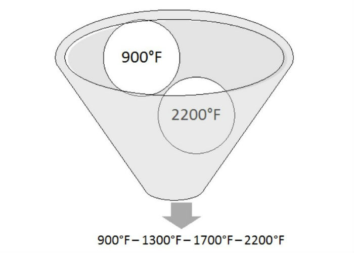
A furnace (in this case, it is irrelevant what type of furnace or what it is used for) processes production hardware from 900°F to 2200°F. Based on the requirements of AMS2750E, the initial TUS would start by testing at 900°F and the last temperature tested would be 2200°F. The supplier would need to select temperatures between 900°F and 2200°F to ensure that there is no more than a 600°F gap between each adjacent temperature. Figure 1 is an example of temperatures that could be selected.


Figure 1


We’ve covered the requirements of an initial TUS; we will now address the conditions when an initial TUS is required. Initial TUSs are required when a) the furnace is installed (new or used) and b) when any modifications are made that can alter the temperature uniformity characteristics. You could dispute this by stating if a TUS fails (and the furnace is then repaired to be put back in service), if the qualified work zone is expanded, if a thicker control thermocouple is installed, etc. a new initial TUS is required. I would agree, but these would all fall under “B”.

Periodic Temperature Uniformity Surveys

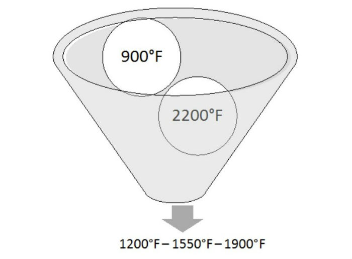
Periodic TUSs are performed for single operating ranges greater than 600°F. In this case, the temperatures are selected must be 300°F from the minimum- and 300°F from the maximum-qualified operating range. If there is a gap of greater than 600°F, additional temperatures must be selected so there is no gap greater than 600°F. Using the example above, we could select temperatures as stated in Figure 2 below.


Figure 2


It is required that at least once each calendar year the minimum and maximum temperatures of the qualified operating range (in our example, it would be 900°F and 2200°F) are tested. Some suppliers may choose to perform an initial TUS once per year to ensure they capture the minimum and maximum.

Initial and Periodic Test Frequency

Tables 8 and 9 within AMS2750E describe the TUS frequency which is based both on furnace Class and Instrumentation Type. As an example, if our furnace referenced previously was identified as a Class 3 (±15°F), Type A instrumentation, the initial survey frequency would be quarterly. After two successful consecutive surveys, the frequency of testing could then be extended to being done annually.

It is important to recognize the difference between initial and periodic TUS temperatures and initial and periodic TUS frequency. Let’s use our example to expand on this. The supplier would perform a TUS using initial temperatures shown in Figure 1. If the TUS passes, the supplier would then, three months later, perform a TUS using the temperatures shown in Figure 2. This would then count as two successful consecutive TUSs. The next TUS could then be performed annually using the temperatures stated in Figure 2.

Conclusion

Understanding initial and periodic TUS requirements is imperative to ensure conformance to AMS2750E and Nadcap. In the next installment, we will discuss TUS data collection, relocation of hot and cold thermocouples, as well as quality requirements.

Submit Your Questions

Please feel free to submit your questions, and I will answer appropriately in future articles. Send your questions to editor@heattreattoday.com.


Jason Schulze on AMS2750E: Initial and Periodic Temperature Uniformity Surveys Read More »

Quartz, Alumina Combine for Innovative Aerospace Castings

A global materials engineering company which designs and manufactures a wide range of high specification products recently released an innovative new material for use in production of turbine engine blades that combines the best of two key materials to improve strength and processing time for the investment casting industry.

The new material, developed by Morgan Advanced Materials, is known as LEMA™. In this Technical Tuesday feature, Eric Larson, Director of Technology and Process Improvement at the Technical Ceramics Business of Morgan Advanced Materials, explains how LEMA™ combines the best aspects alumina and silica (quartz) to provide an effective solution for manufacturers. Content is compiled by Jennifer Kachala, Product Engineer at Morgan’s Technical Ceramic’s business.


Quartz and alumina – the best of both worlds for turbine engine blades

The commercial aerospace industry is on the cusp of significant technological change. High fuel prices, stricter regulations on emissions, and intense competition from low-cost carriers are all driving a quest for more efficient aero-engines and components, where even small advantages can drive major benefits.

Turbine blades are no exception, with a recent report by Market Research Future suggesting that the market for commercial aircraft turbine blades is set to grow at a CAGR of 6 percent by 2023.

Not only is the investment casting industry preparing to meet this demand, but it’s also looking to gain advantages in every aspect of manufacturing, including for the support rods used in the production of turbine engine blades. The two most commonly used materials to cast these are quartz (silica) and alumina.

Both have advantages – and weaknesses. Quartz is the traditional material of choice and has the benefit of being chemically weak and fast to leach, which both accelerates and simplifies production. On the other hand, it is mechanically quite weak which can lead to processing issues and defects during investment casting of difficult metals like super-alloys.

In contrast, alumina rods have about four times the mechanical strength of quartz and are acknowledged for their strength and load-bearing capabilities. However, alumina is so chemically strong it can take several days to fully leach out the material, resulting in longer production times.

While both appear to offer almost opposite properties, they share one common advantage: neither create trace elements which can cause contamination in the process and compromise the quality and performance of parts.

So, neither quartz nor alumina is the perfect material. But what if there was a way of combining the best properties of each to create something new?

The Making of LEMA™

This was the challenge Morgan Advanced Materials set for itself in 2015, resulting in LEMA™, a range of proprietary alumina-based materials that provide double the mechanical strength of quartz while providing significantly improved leaching times, compared with typical high purity alumina.

Like most new inventions, the solution was reached after significant experimentation. The challenge lay in combining two materials and finding the right balance – a complex task, especially as the materials in question were so different.

In search of an answer, Morgan’s laboratories started with a method borrowed from glass science where two distinct phase-separate materials can be used to improve mechanical properties such as toughness or to provide a leaching path through the chemically-weaker glass. In the end an alumina-silicate ceramic was created with a leaching path of silica across the grain boundaries. Particle size distribution and processing parameters were adjusted until the desired mechanical strength was achieved.

Following a period of extensive live testing and refinement, LEMA™ was first introduced to the market in 2017.

Turbocharged Leaching Times, No Loss of Strength

Combining the mechanical properties of alumina with the chemical weakness of quartz, LEMA™ exhibits many unique and valuable properties. It’s almost twice as strong as quartz, and it has a slightly lower thermal expansion coefficient than alumina, which can help with metal leakages sometimes encountered with alumina rods during casting. In addition, LEMA™ is made of pure materials to ensure that the material satisfies the demand for trace element certification.

LEMA™ “crumbles out” when flushed, making it easier to remove during the leaching process. Moreover, like-for-like LEMA™ 250 parts will experience approximately a 20 percent mass reduction after 20 hours (at 300°F [149°C]) and 185 psi). Under the same conditions, a comparable alumina part does not demonstrate any mass loss.

In addition to its advantageous chemical and mechanical properties, LEMA™ also delivers significant commercial benefits. It can reduce investment casting times in turbine engine blades by accelerating leaching by up to 20 percent, solving many of the delays and production challenges which have long been frustrating the global investment industry.

Importantly, as there is less need for autoclave time during the leaching process, manufacturers are spared some of the costly investment in additional equipment. Recognizing the benefits, the industry has already begun to embrace LEMA™; major aerospace manufacturers have used LEMA™ to achieve the desired quality while also reducing costs.

LEMA™ offers a powerful solution for the investment casting of turbine blades, just as the industry is facing an increased demand for these critical components. By bringing together the best aspects of both quartz and alumina, it doesn’t just represent the best of both worlds: it represents a major breakthrough for the industry.


Photo credit and caption: iStock / Jet engine turbine (3D xray blue transparent)

Quartz, Alumina Combine for Innovative Aerospace Castings Read More »

Heat Treaters, First Article Inspection, and AS9102 Compliance


Source: Paulo


Aerospace, automotive, medical and all other industries require FAI — first article inspection, the systematic inspection of new parts to ensure they’ll perform as designed. This includes parts that are subject to heat treatment, which adheres to its own process-specific set of FAI requirements.  This week’s Technical Tuesday feature provides an examination of the exhaustive FAI documentation process for heat treatment of aerospace parts and why it’s so critical.

“Heat treatment almost always distorts parts—it’s the price that comes with enhancing mechanical properties. First article inspections help heat treaters and customers determine whether specified processes will result in acceptable amounts of distortion or if design, material, manufacturing and processing specs need to change.” ~ Paulo


Read more: “First Article Inspections and AS9102 Compliance: How Heat Treaters Fit In”

Heat Treaters, First Article Inspection, and AS9102 Compliance Read More »

Aircraft Manufacturer Begins Construction on New Facility in Alabama

A major European aircraft manufacturer recently began construction on a new U.S. assembly facility for A220 aircraft.

Building has commenced in Mobile, Alabama, where Airbus recently broken ground on the company’s A220 Manufacturing Facility, housing a new assembly line for the newest offering in Airbus’ commercial aircraft product line. The new facility is next to Airbus’ nearby A320 plant. Aircraft production is planned to begin in Q3 2019; with first delivery of a Mobile-assembled A220 aircraft scheduled for 2020. The new A220 production facilities will be complete by next year.


Aircraft Manufacturer Begins Construction on New Facility in Alabama Read More »

Gas Nitriding Capacity Doubles for Range of Applications, Including Auto, Aerospace, Energy

A heat treating services and metallurgical solutions company recently announced the arrival of three new gas nitride units at its corporate headquarters, doubling the gas nitriding capacity at this location and allowing the company to expand its UltraGlow® gas nitriding and UltraOx® surface treatment solutions.

The three new gas nitride units at Advanced Heat Treat Corp’s Waterloo, Iowa, corporate facility vary in size, allowing for the accommodation of various industries and applications including, but not limited to: aerospace, automotive, oil and energy, agriculture, construction, and firearms.

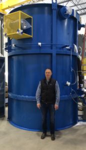
AHT President Mikel Woods with new gas nitriding unit.

One nitride unit will be operational this month, and the additional two units will be running in February. AHT also has plans to design and build an additional unit later in 2019.

“I’m excited on many accounts,” said AHT President, Mikel Woods. “One, we’re adding capacity/back-up to an already growing agriculture/construction market. Two, we have plans to add a new Nadcap process in order to expand further into the aerospace market and meet our customer requirements/requests. And three, we’re gearing up to go even bigger in 2019 with additional equipment.”

The new units will house AHT’s UltraGlow Gas Nitriding and UltraOx services, commonly used in manufacturing to prevent corrosion and improve wear resistance.

“UltraOx is rapidly replacing processes like QPQ/salt bath, chrome plating, and nickel plating; therefore, it was pivotal for us to invest in more equipment so that we can accommodate the growing demand and continue to provide our customers with the quality and service they have come to expect from AHT,” said Woods.

AHT is currently Nadcap accredited for ion nitriding at their corporate location, but with the additional capacity, AHT plans to gain accreditation in gas nitriding by this summer as well. The additional Nadcap accreditation will help AHT to accommodate additional aerospace needs and grow their UltraGlow gas nitriding service.


Photo caption (main): John Ludeman, AHT Quality and Continuous Improvement Manager; Dan Sager, Assistant Operations Manager; Jill Manning, AHT accountant; Carlos Urzagaste, AHT maintenance supervisor

Gas Nitriding Capacity Doubles for Range of Applications, Including Auto, Aerospace, Energy Read More »

Heat Treat Tips: Burn Out vs. Bake Out

During the day-to-day operation of heat treat departments, many habits are formed and procedures followed that sometimes are done simply because that’s the way they’ve always been done. One of the great benefits of having a community of heat treaters is to challenge those habits and look at new ways of doing things. Heat Treat Today101 Heat Treat Tips, tips and tricks that come from some of the industry’s foremost experts, were initially published in the FNA 2018 Special Print Edition, as a way to make the benefits of that community available to as many people as possible. This special edition is available in a digital format here.

Today we offer one of the 101 tips, which was provided by AeroSPC and originally published under Miscellaneous Tips. 


Heat Treat Tip #42

Burn Out vs. Bake Out: What’s the Diff?

Many organizations use the term burn out and bake out to be the same event. Others have burn out understood to be 50°F above prior maximum temperature after the braze process for a short period. Bake out then is a “close to max” temperature of the oven maintained for over an hour. If your organization is using these terms, ensure that they are internally defined and in alignment with the terms used in your customer specifications.

This tip was submitted by AeroSPC.


If you have any questions, feel free to contact the expert who submitted the Tip or contact Heat Treat Today directly. If you have a heat treat tip that you’d like to share, please send to the editor, and we’ll put it in the queue for our next Heat Treat Tips issue. 

Heat Treat Tips: Burn Out vs. Bake Out Read More »

Aerostructures Company Strengthens Boeing Partnership, Expands Manufacturing Facility

The world’s largest first-tier aerostructures manufacturer recently announced that the company plans to expand operations at its Tulsa, Oklahoma, site by investing more than $80 million in capital projects to support fuselage manufacturing and assembly work.

Spirit AeroSystems, Inc., based in Wichita, Kansas, will be hiring about 250 employees as part of this expansion. The new Tulsa project will support increases in 737 production rates by freeing up required space in Spirit’s Wichita factory site.  The work expansion in Tulsa is part of a larger effort to maximize operational efficiencies across Spirit’s sites. As the production rates increase, the Wichita site will continue to hire additional workers to meet the increasing demand.

Spirit AeroSystems President and CEO Tom Gentile

The first phase of the Tulsa work expansion will begin with infrastructure set-up and employee training beginning in 2019. Full rate production is expected to be complete by the end of 2021.  Additional investment in equipment, tooling and facilities upgrades will take place through 2022.

“This expansion would not have been possible without the strong collaboration among Spirit, the UAW, and Oklahoma state and local officials,” said Spirit AeroSystems President and CEO Tom Gentile. “The Spirit team in Tulsa has made great strides in improving the site’s efficiency and demonstrating the capability to bring in additional work. The Tulsa site has a critical role in helping Spirit meet rising airplane production rates and pursue growth opportunities.”

In addition, Spirit announced that it executed a Memorandum of Agreement (MOA) with The Boeing Company, extending its partnership with the aerospace giant and leading manufacturer of airplanes, rotorcraft, rockets, satellites, and missiles worldwide. Spirit builds several important pieces of Boeing aircraft, including the fuselage of the 737, portions of the 787 fuselage, and the cockpit section of the fuselage of nearly all of its airliners.

“This agreement further strengthens the long-standing partnership between Boeing and Spirit as it removes uncertainty well into the next decade. The agreement establishes pricing and capital investment for a range of potential production rate increases on the 737 program. With the new agreement, we expect price to exceed cost eventually on the 787 program. We are excited to continue to build on our relationship and look forward to future opportunities with our largest customer,” said Gentile. “With this agreement, we maintain our target of 7 to 9 percent conversion of revenue to free cash flow.”


Photo caption: Spirit AeroSystems president and CEO Tom Gentile announces Tulsa expansion (Twitter).

Aerostructures Company Strengthens Boeing Partnership, Expands Manufacturing Facility Read More »