Diffusion Bonding in Vacuum Furnaces: A Critical Aerospace Application:

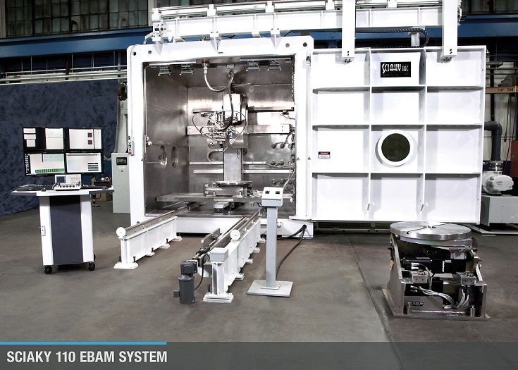
Vacuum heat-treating furnaces are used in a wide range of applications, one of the most critical being the heat treatment of components for aerospace applications. These applications typically allow for metals to be heated to extremely high temperatures with little or no gas contamination. One vacuum furnace application is diffusion bonding. This article, which originally appeared in Heat Treat Today’s March 2019 Aerospace print edition, provides a basic explanation of diffusion bonding of an aerospace part carried out in vacuum furnace.
Diffusion bonding is a solid-state joining process. Parts are bonded or welded together without the use of a bonding filler material between the metals. Instead, the bonding process is based on the atomic diffusion of elements between the metals where the materials meet. It is a very effective process for creating a strong bond between dissimilar materials. The process has been used extensively in the aerospace industry for joining materials and shapes to create components or shapes that could otherwise not be made joined to geometric complexity, e.g., multiple-finned channels and honeycomb structures. Today, many diffusion bonding operations are performed in vacuum furnaces.
The diffusion bonding process relies on four process parameters:
- ultra-low vacuum levels
- temperature
- pressure, and
- time.
All four of these parameters are critical for the successful exchange of atoms between metal surfaces.
Typical Materials Used in Diffusion Bonding
Some metals are more successfully diffusion bonded than others. In the aerospace industry, titanium (Ti) is excellent and widely used. This is due, in large part, to its high specific strength, good erosion resistance, and favorable high-temperature properties. Titanium is 30% stronger than steel yet 40% lighter, and while it is 60% heavier than aluminum (Al), it is twice as strong. Moreover, titanium can be alloyed with other elements such as aluminum, manganese (Mn), iron (Fe), molybdenum (Mo), and other elements to further enhance its considerable strength, particularly at high temperatures. This high-temperature strength is especially useful in the aerospace industry for the containment of combusting rocket engine fuels. Titanium is also valued for its anti-corrosion properties.
In the aerospace industry, titanium is used in manufacturing the structural components of wings as well as skins for hydraulics systems in aircraft, various components of aircraft engines and the cabins of spacecraft, where its qualities are irreplaceable.
Keys to Successful Diffusion Bonding

As mentioned above, diffusion bonding most frequently takes place in a vacuum furnace and is heavily dependent on time, temperature, vacuum levels, and pressure. Let’s take a look at a couple of these parameters as they relate to the vacuum furnace.
Vacuum:
For a successful diffusion bonding process, an ultra-high vacuum level is important. In order for the successful diffusion of atoms to take place between the mating surfaces of the two materials, the surfaces must be microscopically clean. Ultra-high vacuum levels help to prepare the surfaces for a successful bond. The removal of hydrogen is critically important. Any trace of hydrogen could thwart a successful bond. Ultra-high vacuum levels help ensure the elimination of hydrogen from the work area. Also critical is the removal of nitrogen, which, if not eliminated can form nitrides which also can prevent a successful bond. Ultra-high vacuum levels also help remove other trace gases and vapors including oxygen and water, all of which are detrimental to a successful diffusion bond.
Temperature:
Once the desired ultra-high vacuum levels have been achieved – one indication that the surfaces are cleaned and ready for the bonding process to continue – heat is applied to the furnace. The exact temperature of the diffusion bonding process is dependent on the materials being bonded.
Pressure:
Once heat has begun to be applied to the load, argon is typically added to the chamber. Argon, a heavy, inert gas, is typically used in diffusion bonding processes as opposed to nitrogen, because, as stated above, there is a risk of nitride formations if nitrogen is used. Argon avoids this risk. As argon is introduced into the work chamber, and as heat is being applied, the pressure inside the furnace begins to build to the desired level. The exact pressure is dependent on the materials being bonded and other parameters. It is important to note that argon is added during the heat up cycle and not before or after. This is not done 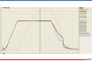 before the heat cycle because the expanding of argon might cause an over-pressure situation resulting in the wasting of argon when the pressure is released. Argon is not introduced into a fully heated furnace because the introduction of cold gases into the furnace would cause thermal cycling (temperature drops) as well as thermal shock to internal furnace parts. A controlled introduction of argon into the furnace is a critical part of the diffusion bonding process.
.
Time:
The final parameter is time. Again, depending on the materials being bonded, the diffusion bonding cycle time can vary significantly.
Diffusion Bonding of Turbine Blades
 Diffusion bonding is often used to produce turbine blades by bonding the two lateral elements of the blade with another titanium shape in the middle. The uncovered surfaces of the internal shape are covered with a layer of ceramic dust. Once the diffusion bonding treatment has been completed, the parts are subjected to super-plastic forming (SPF) where pressure is used to blow out the sides and raise the edges of the intermediary metal. The part is then given the twist typical of an airfoil blade through hot pressing in a die.
Lighter Parts & Increased Fuel Efficiency
Aerospace companies that use blades produced with this method have found a significant improvement in engine performance. Hollow core fan blades produced with SPF/DB processes are lighter and stronger than traditional fan blades. The result is a 5% reduction in fuel consumption. And reduced fuel consumption is something that makes everybody happy.
About the Author: Guido Locatelli is the TAV VACUUM FURNACES SPA Deputy General Manager and Furnacare, Inc. President, an expert in mechanics, materials, and new technologies in the field of vacuum furnaces. Since 1984, TAV VACUUM FURNACES has been producing customized industrial vacuum furnaces worldwide. In 2015, TAV established its American company group Furnacare, Inc., in Spartanburg, South Carolina. This article originally appeared in Heat Treat Today’s March 2019 Aerospace print edition and is published here with the author’s permission.
Diffusion Bonding in Vacuum Furnaces: A Critical Aerospace Application: Read More »