TAT Technologies

Fueling Efficiency: Retrofit Heat Treat Furnace with Combustible Burner Technology

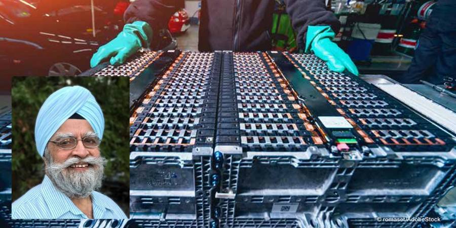
The automotive industry is going electric — electric vehicles are a popular choice for consumers. To continue sustainable efforts for a healthier planet, heat treaters need to seriously consider energy recovery technologies for their equipment and processes. In this Technical Tuesday article, Harb Nayar, founder, president, and CEO at TAT Technologies, examines the use of combustible burner technology (CBT), specifically CBT technology retrofitted on conveyor furnaces that utilize some level of combustible produced by synthetic or generated atmospheres, and that have peak temperatures above 1400ºF (760ºC).


Annealing, brazing, and even powder metal (PM) sintering, metal injection molding, and additive manufacturing offer the automotive industry components with the precision to meet their demanding standards. For example, the nature of PM manufacturing produces minimal waste, both from a material and an environmental perspective. But most in-house and commercial heat treaters fail to capture and reuse energy or convert emissions with environmentally unfriendly pollutants by use of efficient and available gas-neutralizing equipment. These devices capture and thermally combust hydrocarbons, carbon monoxide, and noxious gases such as ammonia.

Figure 1. CBT unit (model based on LBT-I unit)

The reality is that rather than just neutralize these emissions, heat treaters can use them to heat their parts, even before preheating. The focus of this article is to examine the use of combustible burner technology (CBT) and more specifically, CBT technology retrofitted on conveyor furnaces for processes that has the following:

  • Have peak temperature above 1400ºF (760ºC).
  • Utilize some level of combustible (e.g., H2, CO, and CH4) produced by synthetic atmospheres (e.g., N2-H2) or generated atmospheres (e.g., Exothermic, Endothermic and dissociated ammonia).
Here’s a 20-second video of “dancing” flames exiting a conveyor furnace that is sintering PM parts in a N2-H2 atmosphere at 2050°F (1,000+ lb./hr.). Source: TAT Technologies

Recovering Latent Heat Energy

A typical conveyor furnace found on the shop floor has three distinct zones, a preheat zone, a high heat zone, and a cooling zone. Since it is desirable in these units to have a forward atmosphere flow (toward the entrance end of the furnace and opposite the direction of part travel), combustibles emitted while processing the parts exit at the entrance and are typically burned off before entering the room or exhaust system. Often, flames can be seen burning at the front of the furnace. 

Combustible burner technology, aka lubricant burner technology (LBT), is a thermal technology that was originally developed to address issues in the PM industry (Figure 2). This technology can be supplied with or retrofitted on the front of a conveyor furnace to recover latent combustion energy from combustibles (e.g., H2, CO, CH4) or hydrocarbon vapors (e.g., wax lubricants used for PM parts). The energy can be reused to heat parts before entering the preheat zone. This means that the preheat zone itself can be significantly shortened.  

Retrofit Example — PM Sintering Furnace

PM processing is very specific and often more difficult to adopt compared to other continuous atmosphere furnaces. Given the large percentage of PM parts used by the automotive industry, it offers a good example of how heat treaters can achieve energy and cost savings via energy recovery technology.

A Close Look at the Process

Sintering is commonly performed in continuous atmosphere furnaces. In the sintering process, powder metal is combined with a binder, often solid wax (Acrawax®) or stearate-based lubricants are used in the compaction process to make green parts. Delubrication (aka delube, debindering) then takes place in the preheat section of the furnace. There are three phases during PM sintering:

Typical door-to-door time varies between one to five hours, depending upon the material being sintered.

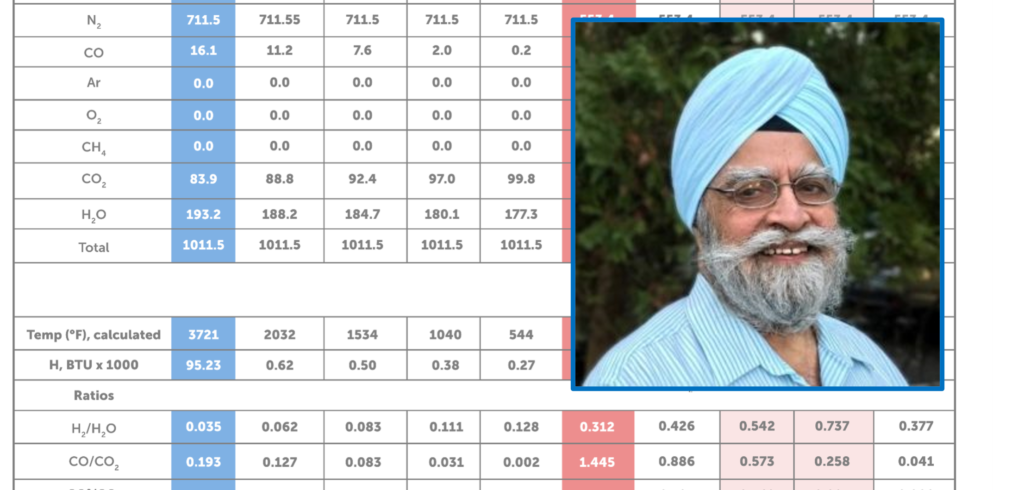
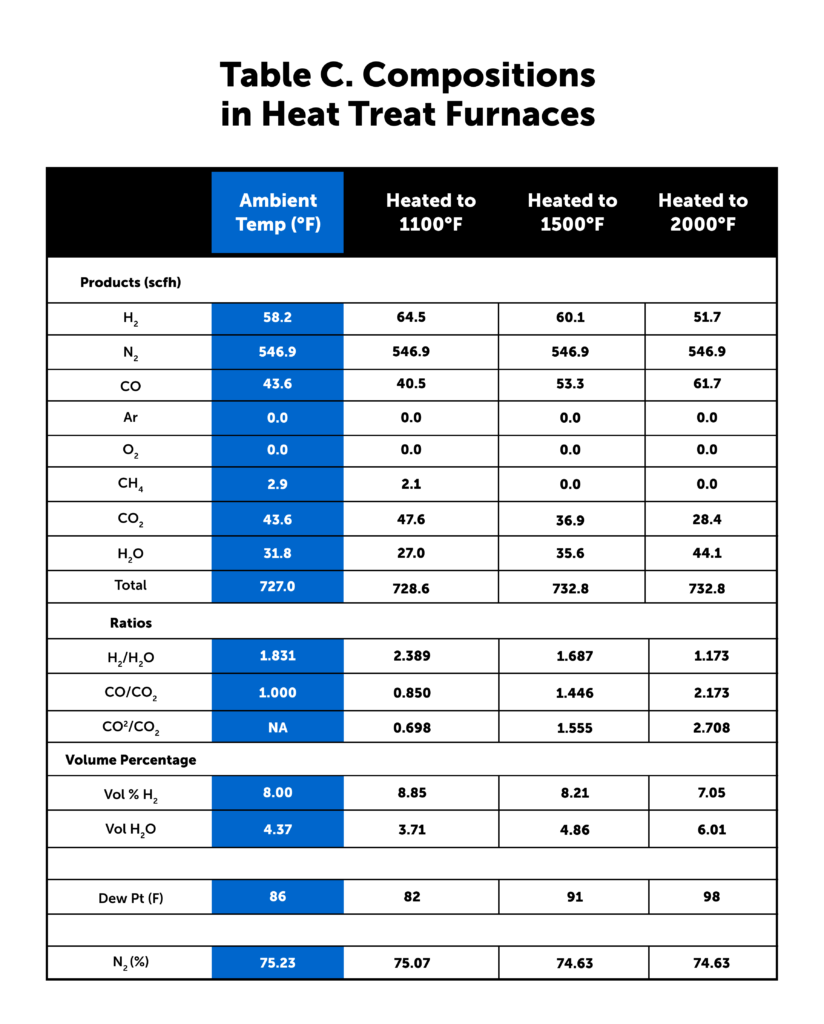
The most common atmosphere used in sintering processes is N2 with 7–20% H2. In other shops, the atmosphere used is Endothermic gas, which has (approximately) 40% H2, 20% CO, with the balance primarily N2 or dissociated ammonia (DA) with a composition of 75% H2 and 25% N2. In some sintering operations, a mixture of DA and N2 is used.

The atmosphere with all the combustibles travels from the high heat section to the preheat section and finally exits from the front of the furnace where the various pollutants are burned off before entering the exhaust system. The total amount of combustibles varies between 10% and 50% depending on the type of atmosphere and material being sintered.

For example, CBT units have been installed for the delubing of tungsten-based alloy parts prior to sintering in high temperature pusher furnaces.

Capturing Latent Energies

During the PM sintering process, users can capture this latent heat to transfer this energy into the green parts prior to the preheat section. The following are approximations of the latent combustion energy available:

  • H2: approximately 0.1 KW per cubic foot of H2 or 0.35 KW per cubic meter of H2
  • CO: approximately 0.12 KW per cubic foot of CO or 0.4 KW per cubic meter of CO
  • Wax lubricant: approximately 5 KW per lb. or 11 KW per kg of lubricant going into the furnace

How CBT Works

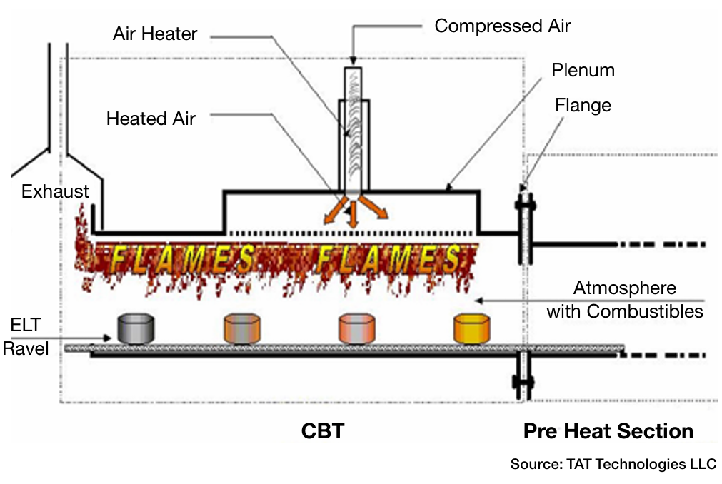
The CBT unit retrofits to the flange of the preheat muffle of the sintering furnace. In its reaction chamber, the furnace atmosphere gases enter from the heating sections carrying the various combustibles. These are circulated in the chamber in which preheated air at 1000–1600°F is introduced through vents in the roof of the chamber (Figure 1).

When the furnace atmosphere and air mix, a combustion reaction takes place with flames being produced over the incoming load of parts that are traveling on the belt towards the preheat section. Heat from theses flames helps vaporize the lubricant and any oils present at a high rate. The lubricant vapors flowing out of the parts are instantly and continuously consumed within the CBT chamber before leaving to enter the exhaust system in the front of the furnace. However, the energy released from the burning lubricants and oil vapors remains, adding to the energy from combustion within the CBT chamber. Enough total heat is generated to heat the parts and the belt to temperature above 930ºF (500ºC) before entering the preheat section. This “recovered” heat energy is essentially free as it is generated from the combustibles and lubricant and oils (e.g., H2 for oxide reduction and lubricant for ease of compaction).

Figure 4. Illustration of the energy generated within the CBT reaction chamber. Parts are moving from right to left. Source: TAT Technologies

Another Case Study Illustration

Energy recovery in a CBT reaction chamber from fully combusting H2 coming from the preheat section of the furnace at a flowrate of 400 CFH (11.3 m3/h) and lubricant coming with the green parts at a rate of 7.2 lbs (3.3 kg) per hour is approximately 235,000 Btu/hr (248 MJ/hr) which is equivalent to an energy savings of approximately 70 KWh of electricity.

Additional Heat Treat Applications

Many other heat treating processes benefit from CBT technology. Some examples follow next.

Annealing often utilizes continuous furnaces.

  • The percentage of H2 in the atmosphere is generally much higher — in some cases 100%.
  • Materials and annealing practices vary from plant to plant.
  • Prior to annealing, the material often has surface oxidation and/or some type of coating (e.g., oils, dry lubricants).
  • The goal is to avoid decarburization and produce an acceptable microstructure, which highly depends on the time/temperature cycle.

Brazing is another thermal process that benefits from CBT technology. 

  • Brazing of most automotive parts is done in either in Exothermic or Endothermic gas or N2-H2 or H2-Ar atmospheres.
  • Materials being brazed are typically low carbon steels or stainless steels. In some instances, other special materials are used.
  • The goal is to have clean, oxide, and soot-free joint surfaces just before the filler metal (commonly copper or nickel-based alloys) melts, flows into the gap between the parts by capillary action, and solidifies producing a homogeneous part.

Summary

Figure 5. Photo shows the main body of a CBT unit. Different product models vary in length and flow capacity, but all produce improvements in product throughput up to 25–50%. Source: TAT Technologies

Heat recovery units like CBT are essential for not only neutralizing harmful furnace gases but oils or other types of organic compounds. This technology allows latent heat energy to be utilized, increasing efficiency and saving energy. Benefits include:

  1. Emission control. Using combustion technology, heat treaters are able to convert potentially harmful pollutants from reaching the exhaust system.
  2. Increased productivity. The technology increases throughput up to 50% depending upon the model used since incoming parts are heated prior to entering the preheat section of the furnace.
  3. Energy savings. The power requirements in the preheat section are reduced and throughput increases up to 50% depending upon the model used.
  4. Improved heat transfer. Parts can be heated to a higher temperature in a shorter amount of time for faster removal of organic materials prior to subsequent reduction of metal oxides.
  5. Decreased unit cost. The energy consumption is lowered and overall cost of parts produced in reduced.
  6. Environmental benefits. Ambient temperature in the front-loading area by 10–30°F is lowered since the burn off flames are significantly smaller. Processes being run are less sensitive to air infiltration in the vicinity of the furnaces.

About the Author:

Herb Nayar
President & CEO
TAT Technologies
Source: TAT Technologies


Harb is an inquisitive learner and dynamic entrepreneur who will share his current interests in the powder metal industry, and what he anticipates for the future of the industry, especially where it bisects with heat treating.


For more information: Contact Harb at harb.nayar@tat-tech.com.


Find Heat Treating Products And Services When You Search On Heat Treat Buyers Guide.Com


Fueling Efficiency: Retrofit Heat Treat Furnace with Combustible Burner Technology Read More »

Exo Gas Composition Changes, Part 2: Cool Down and Use in Heat Treat Furnaces

In Part 1, the author underscored the importance of understanding the changes in gas composition through three steps of its production: first, the production in the combustion chamber; second, the cool down of gas to bring the Exothermic gas (Exo gas) to below the ambient temperature; and third, the introduction of the gas to the heat treat furnace. Read Part 1, published in Heat Treat Today’s August 2023 Automotive Heat Treat print edition, to understand what Exo gas is and to learn about the composition of gas in the first step.


Harb Nayar
Founder and President TAT Technologies LLC Source: TAT

As the author demonstrated in Part 1, Exo gas composition changes in its chemistry for heat treatment; this first step is how the gas composition changes when it is produced in the combustion chamber. The composition of reaction products, temperature, Exothermic energy released, various ratios, and final dew point are all factors that need to be considered to protect metal parts that will be heat treated in the resulting atmosphere.

Now, we’ll turn to Steps 2 and 3.

Step 2: Composition of Exo Gas after Exiting the Reaction Chamber Being Cooled Down

The two examples that follow demonstrate how lean and rich Exo under equilibrium conditions change as they are cooled from peak equilibrium temperature in the combustion chamber down to different lower temperatures (Table B). This cool down brings the Exo down to below ambient temperatures to avoid water condensation.

Example 1: Lean Exo Gas with a 9:1 Air to CH₄ Ratio

The first column highlighted in blue shows the composition of the lean Exo gas as generated in the reaction chamber with an air to natural gas ratio of 9:1. The peak temperature as generated in the combustion chamber is 3721°F. The next four columns show how the composition changes when the lean Exo gas is slowly cooled from 3721°F to 2000°F, 1500°F, 1000°F, and 500°F under equilibrium condition. The following key changes take place as the temperature of the lean Exo is lowered from the peak temperature to 500°F:

  1. Hydrogen volume almost triples from 0.67% to 1.97%.
  2. H₂O volume decreases slightly from 19.1% to 17.5%, but still is very high at all temperatures.
  3. Oxidation-reduction potential (ORP) changes as the H₂ to H₂O ratio increases from 0.035 to 0.111. At all temperatures, it is very low.
  4. CO and the CO to CO₂ ratio drop in a big way, making lean Exo from being decarburizing at higher temperatures to being highly decarburizing at lower temperatures.
  5. The percentage of N₂ remains at 70.34 at all temperatures.
  6. There is no C (carbon, i.e., soot) or residual CH₄ at all temperatures.
  7. For all practical purposes, at an air to natural gas ratio of 9:1, the Exo gas as generated is predominantly an N₂ and H₂ (steam) atmosphere with some CO₂ and small amounts of H₂ and CO.
Table B. Air to Natural Gas at 9:1 and 7:1, cooled to various temperatures

Example 2: Rich Exo Gas with a 7:1 Air to CH₄

The column under ratio of seven is highlighted as red to show the composition of the rich Exo gas as generated in the reaction chamber with an air to CH₄ ratio of seven. The peak temperature is 3182°F — significantly lower than that for lean Exo. The next four columns show how the composition changes when the rich Exo gas is slowly cooled from 3182°F to 2000°F, 1500°F, 1000°F, and 500°F. The following key changes take place as temperature of the rich Exo is lowered from the peak temperature to 500°F:

  1. Hydrogen volume almost doubles from 5.58% at peak temperature to 9.91% at 1000°F, and then it drops to 5.70% at 500°F. The overall volume of H₂ in rich Exo is significantly higher than in lean Exo.
  2. H₂O volume decreases slightly from 17.9% to 15.1%, but it is still very high at all temperatures.
  3. Oxidation-reduction potential (ORP) changes as the H₂ to H₂O ratio increases from 0.312 at peak temperature to 0.737 at 1000°F before decreasing to 0.377 at 500°F. Overall, ORP in rich Exo is significantly higher than that in lean Exo.
  4. CO and the CO to CO₂ ratio drop in a big way, making it mildly decarburizing to more decarburizing
  5. The percentage of N₂ remains at 65– 67%, which is lower than lean Exo.
  6. There is no C (carbon, i.e., soot) at any temperature. However, there is residual CH₄ at 1000°F and lower. This increases rapidly when cooled slowly below 1000°F.
  7. For all practical purposes, the rich Exo gas (at air to natural gas ratio of 7:1) generated is still predominantly a H₂
    and H₂O (steam) atmosphere, but with more H₂; hence, it has somewhat higher oxidation-reduction potential (ORP) than lean Exo and a bit higher CO to CO₂ ratio (less decarburizing than lean Exo).

In summary, rich Exo as generated in the combustion chamber differs from lean Exo as follows:

  1. It has a little less N₂ % as compared to lean Exo.
  2. It has significantly more H₂ , but a little less H₂O than lean Exo. As such, it has a significantly higher H₂ to H₂O ratio (ORP).
  3. It is decarburizing, but less than lean Exo.
  4. It has residual CH₄ at temperatures below 1000°F. Therefore, it must be cooled very quickly to suppress the reaction of developing too much residual CH₄.

Discussion

Let us take the example of rich Exo (an air to natural gas of 7:1) exiting from the reaction chamber in Table B (see column highlighted in red). The total volume is 853.3 SCFH and has H₂O at 152.4 SCFH (17.9% by volume). This is equivalent to dew point of 137°F. Its H₂ content is 47.6 SCFH (5.58% by volume). And the H₂ to H₂O ratio is 0.312.

If this were quenched to close to ambient temperature “instantly,” this composition would be “frozen,” except most of the H₂O vapor will become water. Let us assume the Exo gas was instantly quenched to 80°F (3.6% by volume after condensed water is removed). Rough calculation shows that the final total volume of H₂O vapor has to be reduced from 152.4 SCFH to about 26.0 SCFH in order to meet the 80°F dew point goal. This means 152.4 – 26.0 = 126.4 SCFH of H₂O vapor got condensed to water.

Now the total volume of Exo gas after cooling down to 80°F= 853.35 – 126.4 = 726.95 SCFH, or almost 15% reduction in volume of Exo gas as compared to what was generated in the reaction chamber.

Of course, the composition of Exo gas will not be the same as calculated above. The exact composition after being cooled down depends upon the following:

a. Cooling rate of the reaction products from the peak temperature in the reaction chamber to some intermediate temperature, typically around 1500°F.
b. Cooling rate of the gas from the intermediate temperature to the final (lowest) temperature via water heat exchangers — typically 10–20°F below ambient temperature unless a chiller or dryer is installed on the system.

Depending upon the overall design of the generator, especially how Exo gas coming out of the combustion chamber is cooled and maintained during the period of its use, the expected Exo gas composition should be in the range of the light red columns in Table B — where temperatures are between 1500°F to 1000°F — however:

  1. Total volume closer to 727 SCFH (since a major portion of H₂O was condensed out)
  2. N₂ between 74–77%
  3. Dew point between 80–90°F
  4. CH₄. between 0.1–0.5%
  5. H₂ percentage between 7–9%

Step 3: Composition of Exo Gas after Being Introduced into the Heat Treat Furnace

The cooled down Exo gas will once again change its composition depending upon the temperature inside the furnace where parts are being thermally processed.

As an illustration, let us assume the following composition of the rich Exo gas (with a 7:1 air to natural gas ratio) at ambient temperature just before it enters the furnace:

  • Total volume: 727 SCFH
  • H₂: 8% (58.16 SCFH)
  • Dew Point 86°F or 4.37% (31.77 SCFH)
  • CO: 6% (43.62 SCFH)
  • CO₂: 6% (43.62 SCFH)
  • CH₄ : 0.4% (2.91 SFH)
  • Balance N₂ (%)
  • 75.23% (546.92 SCFH)

Table C shows how the composition changes once it reaches the high heat section of the furnace where parts are being thermally treated. The column highlighted blue shows the composition of Exo gas as it is about to enter while it is still at the ambient temperature. The next three columns show the composition of the Exo gas in the high heat section of furnaces operating at three different temperatures depending upon the heat treat application — 1100°F like annealing of copper, 1500°F like annealing of steel tubes, and 2000°F like copper brazing of steel products. The H₂ to H₂O ratio decreases as temperature increases.

Other general comments on Exo generators:

  1. Generally, they are horizontal.
  2. Size ranges from 1,000 to 60,000 SCFH.
  3. Rich Exo generators use Ni as a catalyst in the reaction chamber. Lean Exo does not.
  4. Lean Exo generators typically operate at a 9:1 air to natural gas ratio. There is no carbon/soot buildup.
  5. Rich Exo generators typically operate at a 7:1 air to natural gas ratio. Below about 6.8 and lower ratios, soot/carbon deposits start appearing that require carbon burnout as part of the maintenance procedure.
Table C. Exo gas compositions in heat treat furnaces

Conclusions

A walkthrough of the entire cycle of gas production to cool down to use in the high heat section of the furnace clearly shows that as temperature changes, so does the Exo gas composition for any air to natural gas ratio.

Having a well-controlled composition of Exo gas requires the following:

  • Well-controlled composition of the natural gas used
  • Air supply with controlled dew point
  • Highly accurate air and natural gas mixing system
  • Highly controlled and maintained cooling system
  • A reliable ORP analyzer or the H₂ to H₂O ratio analyzer as part of the Exo gas delivery system.

Protecting metallic workpieces is paramount in heat treating, and in order to do this, the atmosphere created by Exothermic gas must be understood, both in the cool down phase and within the heat treat furnace. For further understanding of the good progress made in the improvement of Exo generators, see Dan Herring’s work in the reference section below.

References

Herring, Dan. “Exothermic Gas Generators: Forgotten Technology?” Industrial Heating, 2018, https:// digital.bnpmedia.com/publication/?m=11623&i=53 4828&p=121&ver=html5.

Morris, Art. “Exothermic Atmospheres.” Industrial Heating (June 10, 2023), https:// www.industrialheating.com/articles/91142-Exothermic-atmospherees.

About the Author

Harb Nayar is the founder and president of TAT Technologies LLC. Harb is both an inquisitive learner and dynamic entrepreneur who will share his current interests in the powder metal industry and what he anticipates for the future of the industry, especially where it bisects with heat treating.

For more information: Contact Harb at harb.nayar@tat-tech.com or visit www.tat-tech.com


Find Heat Treating Products And Services When You Search On Heat Treat Buyers Guide.Com

Exo Gas Composition Changes, Part 2: Cool Down and Use in Heat Treat Furnaces Read More »

Skip to content