



Paulo Duarte

Improve Vacuum Quench, Maximize Tool Life

Vacuum furnaces performing hardening have been in use for over 50 years, yet many heat treaters may not be taking full advantage of newer, more advanced analysis tools and methods. Controlling the cooling pressure can dramatically improve toughness and tool life, but only if applied with precision. In this Technical Tuesday installment, Paulo Duarte, technical director at Treatnorte, explores the science behind gas quenching, the role of step cooling, and why measuring and adjusting cooling curves is critical for consistent, high-performance results.

This informative piece was first released in Heat Treat Today’s March 2026 Annual Aerospace Heat Treating print edition.


Introduction

It has been a long time since the invention of the vacuum hardening process, yet innovation in this field continues. In recent years, industrial furnaces capable of operating with higher cooling gas pressures — up to 15 bar now commonly offered on the market — have become standard. But do we truly know how to make the best use of such high pressures?

Pressures up to 10 bar were first applied to cool small parts made from cold-work tool steels, such as sheet metal stamping tools. However, such high pressures can lead to cracking in larger hot-work steel dies when cooled directly. Step cooling was introduced as a solution: start with a fast initial cooling at higher temperatures to avoid carbide formation, then gradually lower pressure stages during the final cooling phase to reduce distortion and minimize the risk of crack appearance.

Despite this empirical knowledge, the question remains: do we really understand what we are doing? Are we routinely measuring cooling rates to determine where they stand on the CCT diagram, predicting microstructure and properties, and adjusting quenching parameters accordingly? And are we certain about which pressures to use for producing high-performance, demanding tools?

Cooling in Vacuum Furnaces

Quenching is one of the most critical steps in the hardening cycle. It transforms austenite into the optimal final microstructure, avoiding the formation of coarse carbides and pearlitic constituents during cooling. This ensures the finest possible microstructure.
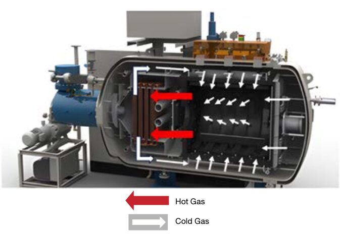
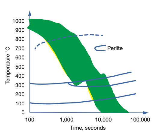
Figure 1. Gas quenching in a vacuum hardening furnace | Image Credit: SECO/WARWICK
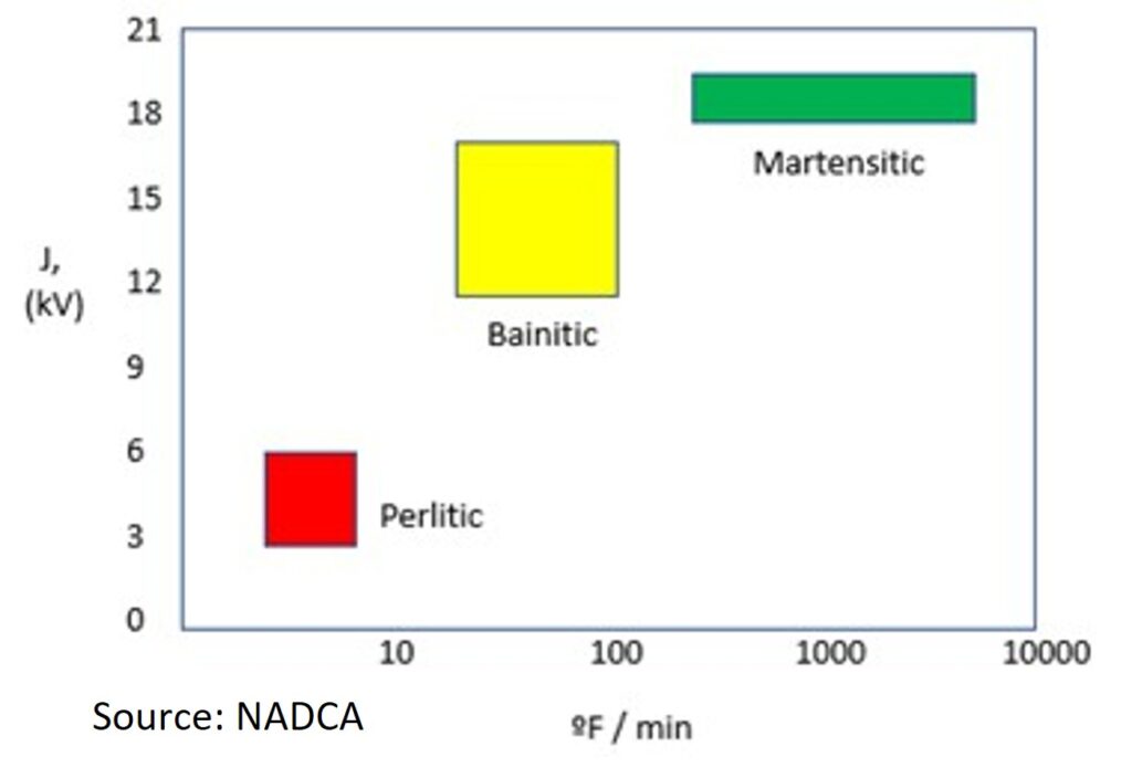
Figure 2. Surface cooling rates region on systematic analysis of parts quenching in a 600 mm x 600 mm x 900 mm furnace. Parts comprising weights from 500 up to 1,000 kg. Cooling pressures varies from 4 to 5 bar. Hot work tool steel. | Image Credit: Metaltec Solutions

In vacuum furnaces, this is typically achieved by injecting cooling gas through nozzles directed at the surface of the parts located in the furnace hot zone. During cooling, the gas circulates through the chamber, being drawn through furnace ports into contact with the heat exchanger tubes. A turbine then blows the cooled gas back into the hot zone where the load is located (Figure 1).

The higher the programmed cooling pressure, the greater the volume of gas passing through the nozzles over the same period of time. This increases the heat transfer from the parts to the cooling gas, resulting in a faster cooling rate.

By measuring successive cooling curves for different loads, specifically for single hot-work steel tools weighing over 500 kg, surface cooling rates pass through the bainitic–martensitic domain (the green area of the CCT diagram shown in Figure 2). Thinner parts tend to cool closer to the martensitic end at the Ms-Bs intersection, while larger tools tend to approach the pearlitic nose.

These observations highlight the importance of adjusting cooling pressure to produce the desired microstructure and account for the different cooling behaviors of large, medium, and small parts.

Investigative Approach: Testing Furnace Data Against CCT Diagrams

Measuring part temperatures during cooling began over 20 years ago, using thermocouples and data loggers, and comparing the results to steel continuous cooling transformation (CCT) diagrams. Most vacuum furnaces do not include this capability as standard, and when available as optional software, many companies choose not to invest in it. In 2005, it was discovered what few in the industry knew at the time: hardening hot-work tool steels in industrial vacuum furnaces often results in a bainitic–martensitic microstructure. This phenomenon is now more widely recognized, with published cooling curves overlaid on CCT diagrams for larger tools becoming more available.

Even so, open discussion remains rare, partly because many heat treaters are reluctant to present this evidence to academia, fearing criticism that their results do not match the fully martensitic microstructure taught at universities. This is not a debate about right or wrong, but rather an opportunity for research and improvement in heat treatment practices worldwide.

After initial testing with a 600 mm × 600 mm × 900 mm French-made single-chamber furnace, trials continued with a larger 900 mm × 900 mm × 1,800 mm German-made vacuum furnace. These tests began by measuring both surface and core temperatures for repeated cycles with small and large charges ranging from small cold-work tools to hot-work tool steel parts weighing 500–1,500 kg. Leading vacuum furnace manufacturers in North America and Europe have developed technologies capable of successfully heat treating small, medium, and large tools, resulting in microstructures that often contain both bainite and martensite. This is, in fact, an inherent characteristic of the technology. Such tools have performed well in service for decades. That said, heat treaters using higher cooling pressures have seen improved tool life significantly, while also increasing the risk of treatment failures if the pressure is too high.

In the last 10 years, properties and microstructure analyses have shown that variations in cooling rate can significantly change the microstructure and toughness of the part even within the same bainitic–martensitic domain of the CCT diagram.

With the emergence of Industry 4.0 and 5.0, along with digitalization and AI, systematic research into heat treatment processes combined with quenching deformation simulation can lead to better selection of cooling pressures. This is a critical parameter in controlling the hardening process, and it has a direct impact on part toughness and service performance. Metaltec Solutions introduced one of the first software tools aimed at improving vacuum heat treatment through Industry 4.0 concepts in 2017. This technology represents a step toward greater awareness and precision in tool steel hardening, helping heat treaters program their cycles for optimal performance in demanding applications.

Regulating Pressure in Vacuum Hardening Furnaces

To obtain the best possible microstructures, gas quenching must be programmed in the furnace so that the cooling rate is kept as close as possible to the martensitic end, i.e., at the Ms-Bs intersection, of the CCT diagram, avoiding the formation of coarse and undesirable microconstituents in the steel. This is achieved by selecting the highest permissible cooling pressure that still prevents cracking or excessive deformation. While small parts can withstand direct high-pressure cooling, larger tools require a reduction in cooling pressure.

Preliminary Pressure Comparison

For optimal quenching of large parts, the cooling pressure should not remain constant throughout the entire cooling cycle. Instead, high pressure should be applied during the initial cooling stage to prevent coarse carbides and pearlite formation and then reduced when the surface temperature reaches approximately 550°C (1022°F). This creates a martempering stage at lower pressures, reducing the risk of distortion and cracking.
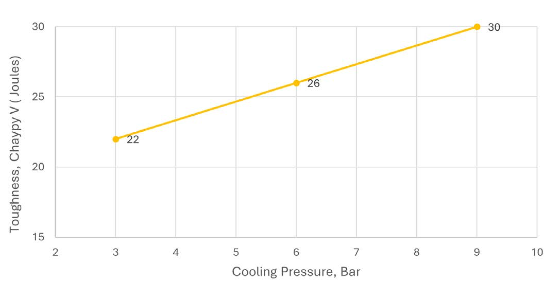
Figure 3a. Cooling pressure effect on Vidar Superior (an H11 steel grade
variation) part surface toughness | Image Credit: Metaltec Solutions
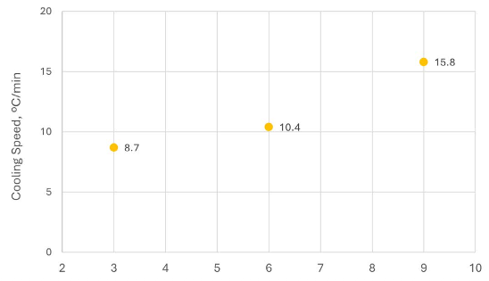
Figure 3b. Cooling pressure effect on 400 mm x 400 mm x 400 mm
block surface toughness | Image Credit: Metaltec Solutions

If we measure the toughness of steel pieces quenched at different cooling pressures, then tempered together to achieve a typical 46–48 HRC hardness (in hot work tool steel), we find that higher cooling pressures result in greater toughness. Using older furnace pressures (around 3 bar) yields lower toughness, whereas increasing cooling pressure can improve toughness by approximately 60% (Figure 3a). This translates into longer tool life, since high-pressure-quenched tools better absorb stress, delaying the initiation and propagation of cracks. These benefits result from higher cooling rates (Figure 3b) and the corresponding finer microstructures achieved.

Although quenching at 3, 6, and 9 bar passes through the same transformation domain on the CCT curve, differences in the resulting internal steel structure, whether coarser or finer, are clearly observable.

True Toughness and Speed

Looking in more detail at the above findings, we can observe that when parts are cooled in a 900 mm × 900 mm × 1,800 mm vacuum furnace, the gas temperature drops below the Ms temperature (for typical hot work tool steels) in less than one minute. The gas temperature then remains near room temperature during the subsequent cooling of the parts (Figure 4a).
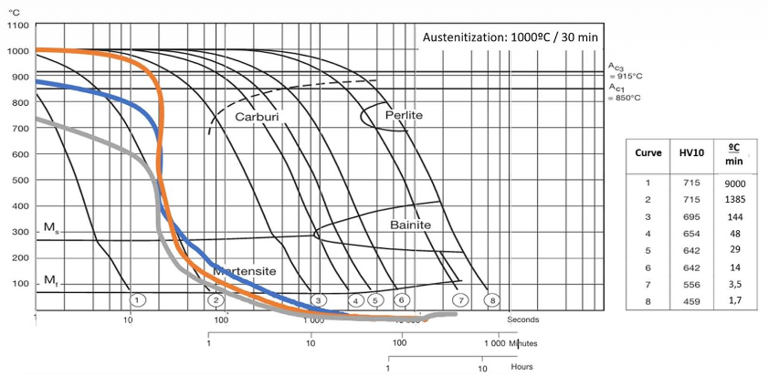
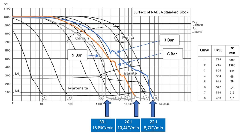
Figure 4a. Cooling NADCA block in a large vacuum hardening furnace; gas cooling rate according to gas pressure used | Image Credit: Metaltec Solutions
Figure 4b. Cooling NADCA block in a large vacuum hardening furnace; surface cooling curves and its respective toughness after tempering, with the alteration of the cooling curve behavior provided by the martempering (final hardness level 46–48HRC hot work tool steel | Image Credit: Metaltec Solutions

The parts, however, take considerably longer to cool down to the furnace unloading temperature, depending on the cooling pressure applied. When analyzing the cooling of large dies using the NADCA block as the standard size for comparison, the surface cooling curves vary according to the applied pressure, falling into the bainitic–martensitic domain for 3, 6, and 9 bar cooling pressures.

From this data, it can be seen that hardness is not significantly affected by using 3, 6, or 9 bar cooling pressures, even though the higher pressures produce cooling rates up to twice as fast as the slower ones. Toughness, however, is largely influenced by the way the cooling curves pass through the bainitic–martensitic domain, whether crossing the Bs and Ms intersection closer to the martensitic end (9 bar), near the center (6 bar), or closer to the pearlitic nose (3 bar).

Tuning Pressure and Time

These results show that, within the typical cooling rates of vacuum hardening (Figure 2), toughness varies significantly with cooling pressure, corresponding to finely tuned cooling speeds ranging from approximately 9 to 16°C/min (48 to 61°F/min) between 800°C and 500°C (932°F and 1472°F). This highlights the need to use the highest possible cooling pressures to achieve excellent properties while avoiding direct high-pressure cooling of large parts by applying step cooling with an initial fast cooling phase, followed by reduced pressure.

How Microstructure Drives Toughness

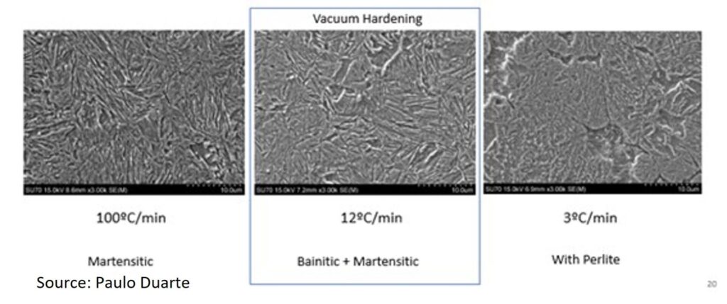
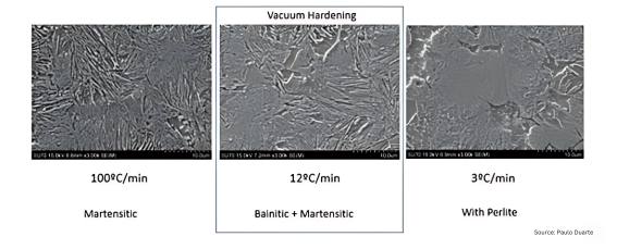
The reason for achieving better properties at higher cooling pressures lies in the resulting microstructure, as shown in Figure 5. Fine bainite and martensitic needles, formed through faster cooling rates, are responsible for the higher toughness observed. When lower cooling pressures are used, the cooling rate decreases, leading to coarser needle sizes (Figres 5a–c) and, consequently, lower toughness values.
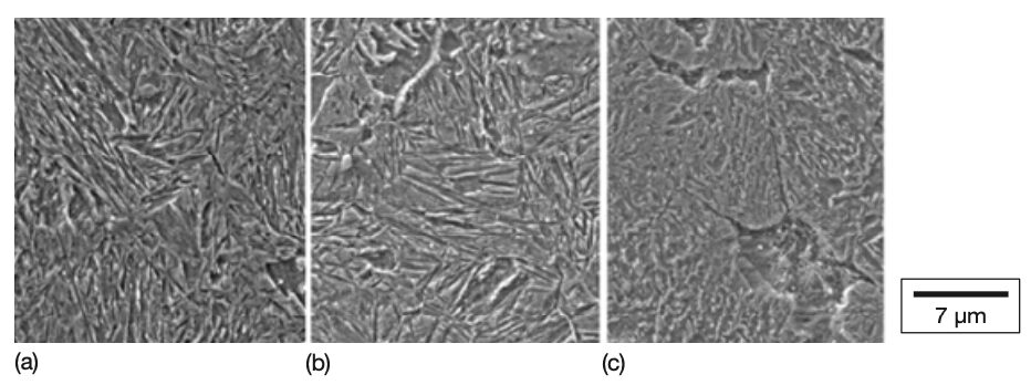

Figure 5a-c. Microstructures obtained after quenching Orvar Supreme (premium H13 steel): a) 100°C/min; b) 12°C/min; c) 3°C/min (or, a) 180°F/min; b) 22°F/min; c) 5°F/min) | Image Credit: Metaltec Solutions
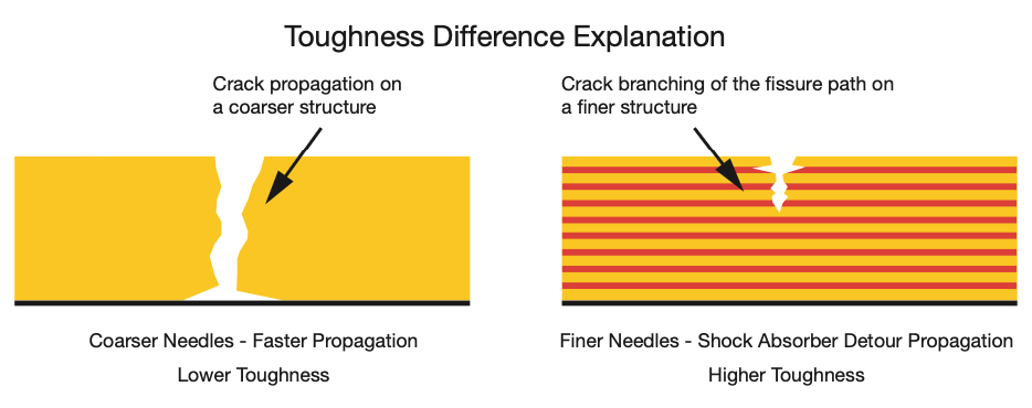
Figure 6. Toughness model | Image Credit: Metaltec Solutions

This can be explained by Figure 6. In a coarser microstructure, cracks can propagate more easily because there are fewer obstacles to their advance. In finer microstructures, the higher density of needles forces cracks to deviate repeatedly from their path due to the branching effect, altering the directions of crack propagation. This “shock absorber” effect — caused by the frequent detours a crack experiences when traveling through a greater number of fine needles — is the reason for the toughness improvement observed when higher cooling pressures are used to achieve faster cooling rates.
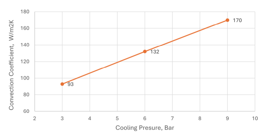

Figure 7. Convection coefficients for a 900 mm × 900 mm × 1,800 mm vacuum hardening furnace according to the pressure being used | Image Credit: Metaltec Solutions

Each furnace behaves differently, from one furnace builder to another and also depending on the level of maintenance of a furnace. So a similar furnace to the one used for obtaining cooling curves and corresponding toughness values (Figure 4b) was used to obtain the convection coefficients (Figure 7). We can see a strong correlation between convection coefficient, pressure, and final toughness obtained, indicating that these features must be carefully adjusted to reach optimal part properties and longer service life.

Conclusion

Properly applying cooling pressures, through direct high-pressure cooling for small loads or step cooling for larger tools, can significantly increase part toughness and extend tool life. The key lies in understanding how cooling curves interact with the bainitic–martensitic microstructure and adjusting pressure according to part size, geometry, and furnace characteristics.

By measuring temperatures, analyzing microstructures, and fine-tuning cooling cycles, heat treat operators can achieve consistent, high-performance results, as demonstrated with the above studies on tool steels. Faster, well-controlled cooling typically produces finer bainitic–martensitic microstructures which results in a part with “shock absorber” qualities.

Ultimately, maximizing cooling pressure, not just for minimal distortion, creates more durable tools, reduces downtime, and strengthens competitiveness through part performance.

About The Author:

Paulo Duarte
Technical Director
Treatnorte

Paulo Duarte is an independent researcher and consultant on heat treat technologies, also working as technical director at Treatnorte. His education and expertise in metallurgy have culminated in several articles and patents. Previously, he was the project manager at Metalsolvus and also had been the technical manager and heat treatment manager within bohler-uddeholm group for the Portuguese market. Currently, Paulo focuses on helping heat treaters by providing innovative, more efficient, and profitable heat treatment services to companies.

For more information: Contact Paulo Duarte at pauloduarte@treatnote.pt.

Improve Vacuum Quench, Maximize Tool Life Read More »
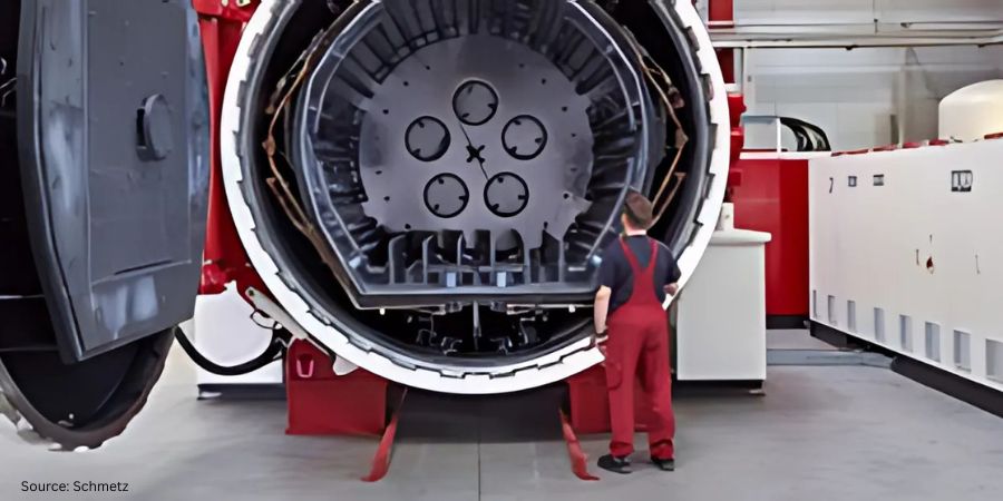
Improving Hardening and Introducing Innovation for In-House Heat Treat

In this Technical Tuesday by Paulo Duarte, project manager, Metalsolvus, explores how digital tools lead the way in vacuum hardening operations to ensure energy efficiency and processing repeatability.

This piece was originally published in Heat Treat Today’s March 2025 Aerospace print edition.


Vacuum hardening has been the chosen process for hardening tools used in plastic injection, die casting, and metal sheet stamping over the past few decades. Although widely used and accepted, there is still room for improvement in tool performance through quality-driven procedures. By employing easy methods of measurement, study, and testing, it is possible to enhance part integrity and mechanical properties, while simultaneously reducing heat treatment time and energy consumption. Advanced metallurgical analyses of heat treatment cycles and equipment can introduce better tools on the market, as well as provide time and cost saving heat treatments.

Basics of Vacuum Hardening

In vacuum hardening furnaces, temperature and time are carefully controlled at specific load locations to ensure optimal hardening. Optimal
practices focus on heating and soaking the metal parts during heat treatment. The controlled introduction of vacuum and inert gases during the process ensures the right protective atmosphere for treatment, resulting in steel that is mainly free from oxidation and decarburization. This preserves the surface integrity of the tools.

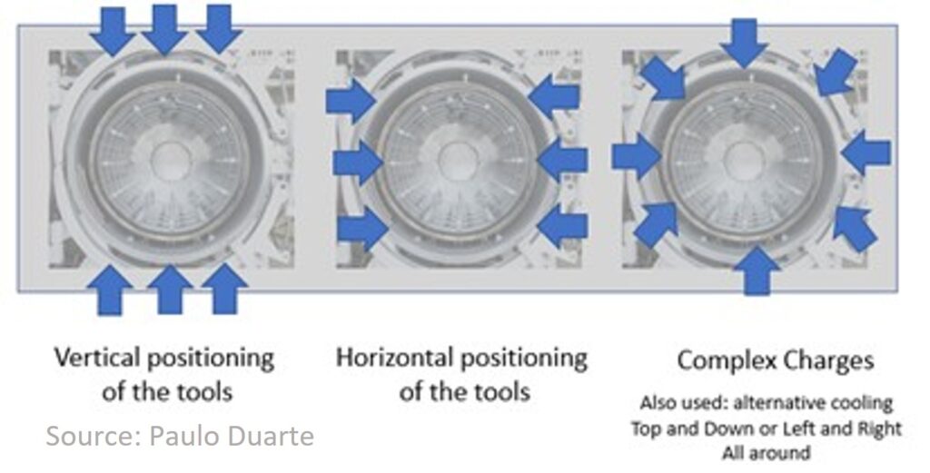
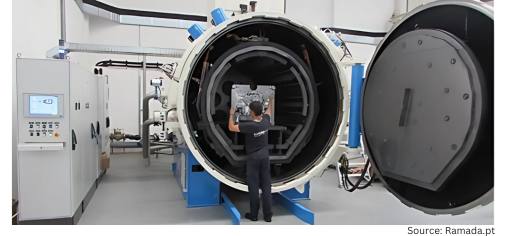
Cooling is achieved through the injection of an inert gas into the heating chamber, with controlled pressure and adequate recirculation between the heat exchanger and the hot zone (Figure 1). Different gas injection directions are utilized depending on the load being treated, ensuring optimal cooling.

Figure 1. Cooling parts in vacuum hardening furnaces — inert gas injection on the hot chamber during cooling

Hardening of Large Tools

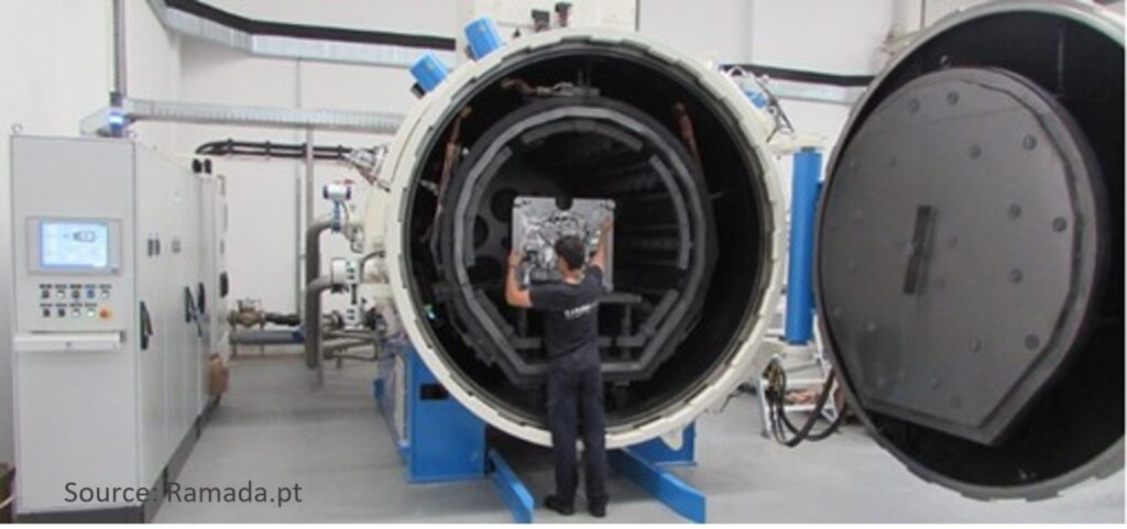
Heating and quenching large tools is one of the most challenging situations for vacuum hardening, as temperature control and part microstructure integrity are more difficult to obtain, which affects part quality. Large tools, typically made of hot work tool steels, are hardened in large furnaces. To minimize deformation, parts are preferably positioned vertically inside the furnace (Figure 2).

Figure 2. Large molds positioned inside the vacuum hardening furnace, two parallel cavities

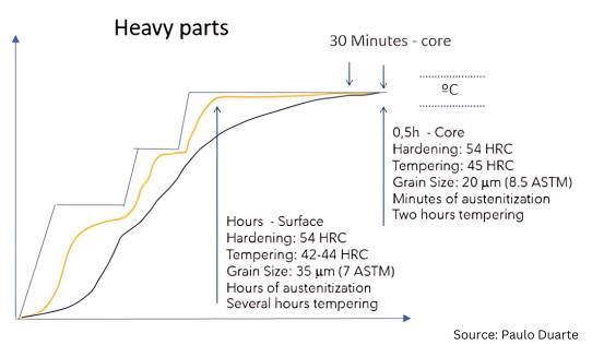
Surface soaking times for big tools can significantly exceed standard austenitization and tempering times due to thermal gradients existing within the
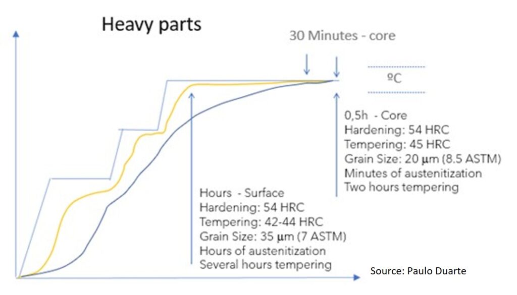
parts. Mold cores usually achieve the right soaking and tempering recommendation through accurate temperature control, monitored by well-positioned core thermocouples. A tool’s microstructure and performance will depend heavily on geometry, size, and temperature uniformity achieved during treatment. See Figure 3 for the core and surface typical hardening cycles for large tools.

Figure 3. Heating and soaking cycle for the hardening of large tools (“Heat Treatment of a AISI H11 Premium Hot-Work Tool Steel”)

The cooling phase is crucial in determining the final properties of both the surface and core of the tool. Higher gas injection pressures result in faster
cooling and increased toughness, but this also introduces greater deformation risks, when directly cooled from austenitization temperature, so martempering done at low pressures is usually required.

Balancing cooling pressure is one of the most secret topics in vacuum hardening. With a variety of parameters and procedures used among heat treaters, measuring and testing is essential for achieving consistent quality for better controlling the hardening process and attaining the best part quality.

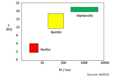
Figure 4. Microstructure and toughness obtained after the use of different hardening cooling rates (image from Transactions of the 15th NADCA Congress, 1989)

The use of higher or lower inert gas pressures directly affects the cooling rate, making it faster or slower, respectively. Regulating the gas injection pressure during the cooling phase significantly impacts the material’s toughness, even when cooling occurs within the bainitic-martensitic domain commonly observed in vacuum hardening practices. Faster cooling leads to finer microstructures, which in turn results in tougher materials. However, fully martensitic microstructures are rarely achieved in industrial vacuum hardening furnaces and are typically limited to smaller loads composed of
small parts. In larger parts, the risk of pearlite formation increases, especially when cooling rates fall around 3°C/min (5°F/min) at the core, as illustrated in Figures 4 and 5.

Figure 5. Microstructure of Uddeholm Orvar Supreme steel after quenching using different cooling rates

In industrial heat treatments of large tools, accurately monitoring core temperature is challenging, as it is difficult to position a thermocouple hole exactly at the innermost location or a nearby region. This makes it harder to control the hardening process and prevent pearlite formation. Therefore, studying the process to establish effective control measures is essential for achieving the highest possible quality.

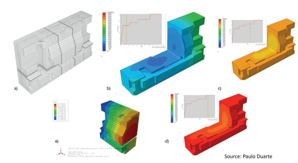
Heat treatment simulation simplifies this task by allowing the hardening process to be predicted, with thermal gradients estimated and compensated through furnace control parameter adjustments. Figure 6 presents a real case study, where the temperature distribution inside a large mold was fully characterized during the entire heat treatment cycle using FEM (Finite element method) simulation and validated through actual thermocouple measurements. FEM simulation, as a proven and highly effective technique for predicting heat treatment cycles, enables heat treaters to implement optimized, computer-supported heat treatment practices.

Figure 6. Mold temperature gradients during vacuum hardening: a) FEM mesh, b) gradients during heating at lower temperatures, c) gradients at the last pre-heating steps, and d) gradients during austenitization from Maia et al. “Study of Heating Stage of Big Dimension Steel Parts Hardening”; e) gradients during mold cooling from Pinho et al. “Modelling and Simulation of Vacuum Hardening of Tool Steels”

Vacuum Hardening Standard Block
Size and Cycle Forecast

When working with loads composed of small to medium-sized parts, the core temperature of the load can be monitored using dummy standard blocks. These blocks have a central hole to accommodate the thermocouple used to control the heat treatment cycle. The dummy block should be selected to
closely match the size of the largest part in the load. However, in commercial heat treatment settings, part sizes can vary widely, making it di cult to maintain a comprehensive set of dummy blocks that represents all possible heat treatment scenarios.

Once again, simulation proves valuable in helping heat treaters gather useful data to anticipate the heat treatment cycle and determine the appropriate range of dummy blocks to have available on the shop floor. The procedure for selecting the dummy block range and forecasting the corresponding
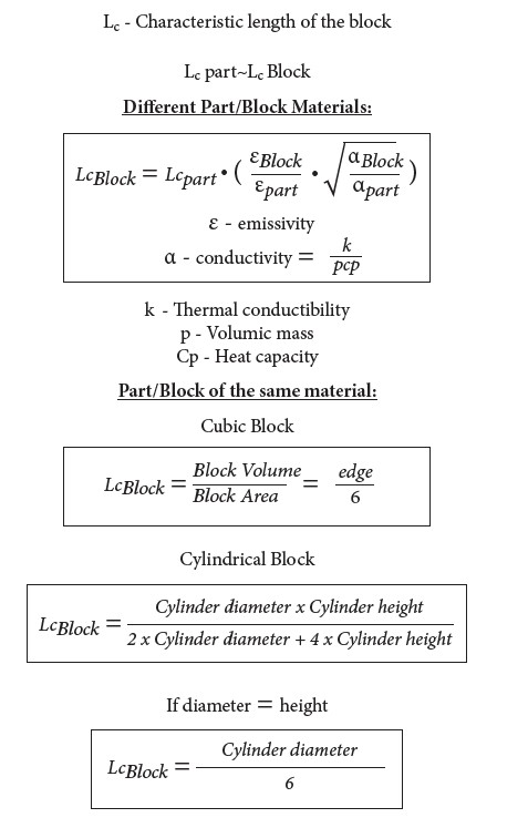
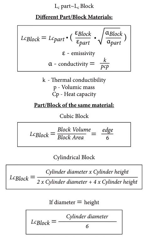
heat treatment times is outlined in the following equations. Ideally, the standard block should be made from the same material as the largest part in the load. If the materials differ, the characteristic length of the block can be calculated using the first of the following equations.

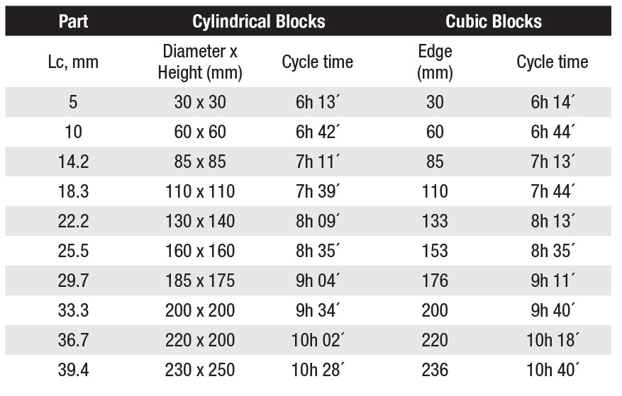
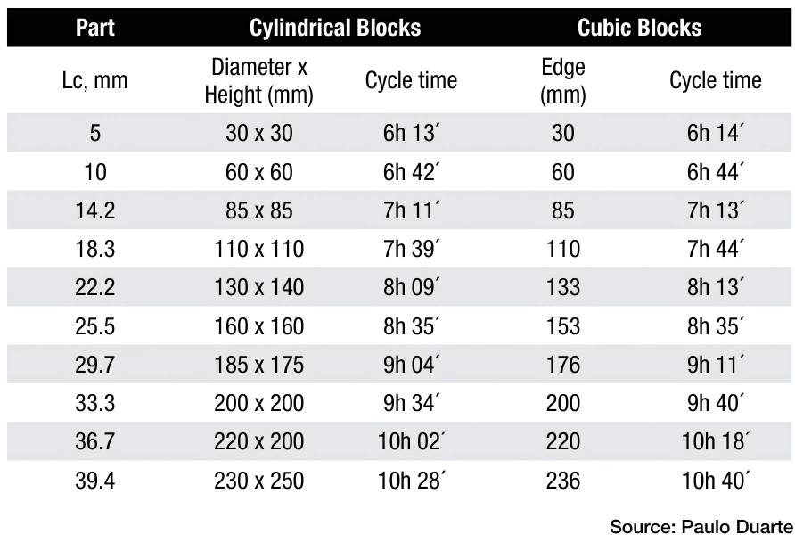
Table 1. Proposed dimensional distribution range for cubic and cylindrical standard blocks and expected cycle times in a typical 600 x 600 x 900 mm hardening furnace (data from Figueiredo et al., “Study of a Methodology for Selecting Standard Blocks for Hardening Heat Treatments”)

Table 1 lists a range of proposed dummy block sizes to be used for monitoring the load temperature during heat treatment. The time to end of soaking at higher temperature is also given by Table 1 for a typical 600 x 600 x 900 mm hardening furnace. Times were obtained by FEM simulation and can be used to forecast the end of austenitization in a hardening process of each dummy block.

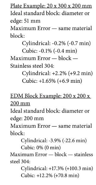
The simulated times were validated by using real parts temperature measurement by thermocouples. These were the calculated errors based on simulation and heat treat validation trial:

  • Plate Example: 20 x 300 x 200 mm
  • Ideal standard block: diameter or edge: 51 mm
  • Maximum Error — same material block:
    • Cylindrical: -0.2% (-0.7 min)
    • Cubic: -0.1% (-0.4 min)
  • Maximum Error — block — Stainless steel 304:
    • Cylindrical: +2.2% (+9.2 min)
    • Cubic: +1.65% (+6.9 min)
  • EDM Block Example: 200 x 200 x 200 mm
  • Ideal standard block: diameter or edge: 200 mm
  • Maximum Error — same material block:
    • Cylindrical: -3.9% (-22.6 min)
    • Cubic: 0% (0 min)
  • Maximum Error — block — stainless steel 304:
    • Cylindrical: +17.3% (+100.3 min)
    • Cubic: +12.2% (+70.8 min)

Optimizing the Vacuum Hardening of Tools

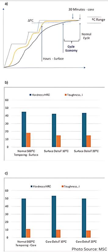
Figure 7. Effect of selecting different temperature (T) range for starting to control the isothermal stage time. a) T criteria and respective cycle time reduction; b) surface mechanical properties obtained by using different T; and c) core properties after tempering at different T range (Miranda et al., “Heat Treatment of a AISI H11 Premium Hot-Work Tool Steel,” MSC)

FEM simulation can also be used to optimize the heat treatment process, but metallurgical testing remains crucial for providing reliable insights into safely reducing cycle time and energy consumption. Typically, for setting the isothermal stage time, a tolerance of -5°C relative to the temperature setpoint is used, leading to savings in both heat treatment duration and power consumption, as shown in Figure 7a. However, Figure 7b demonstrates that higher tolerance values (ΔT) can be considered. Tolerances of up to -10°C or even -20°C can be applied for controlling the soaking time without significantly affecting the hardness and toughness of the parts. Naturally, these results depend on the desired setpoints for the isothermal stages, but Figure 7c reflects the worst-case scenario for ΔT, referring to the use of lower austenitizing and tempering temperatures commonly applied in the hardening of hot-work tool steels.

Future Trends of Vacuum Hardening

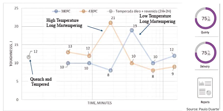
Innovations like digitalization, automation, and resource reduction, as part of Industry 5.0 initiatives, are expected to drive advancements in heat treatment processes. Long martempering, a heat treatment under development for hardening hot-work tool steels, shows promise as an alternative to traditional quenching and tempering. This process offers a balance of high hardness and toughness in significantly less time, providing energy savings and faster turnaround.

Figure 8. New long martempering heat treatment cycle: AISI H13 premium toughness for two different long martempering temperatures (“Study of The Bainitic Transformation of H13 Premium Steel”)

New Vacuum Hardening Process — Long Martempering

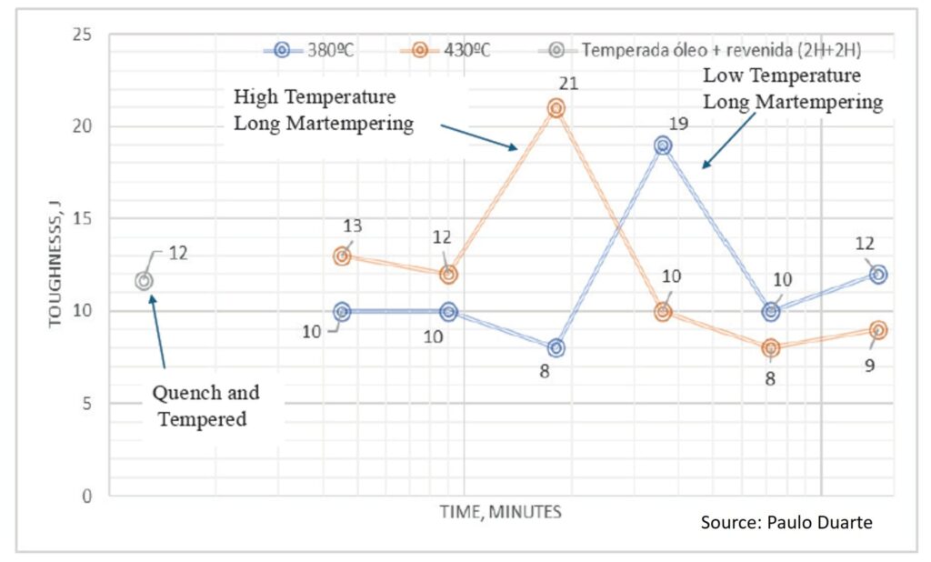
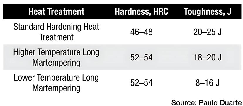
Long martempering is a heat treatment under development that can be used to harden hot-work tool steels. Long martempering is a process somewhat similar to austempering but is applied to steels rather than cast irons. Performed at temperatures within the martempering range, long martempering corresponds to an interrupted bainitic heat treatment with a specific process window (Figure 8) where high toughness is achieved at hardness levels exceeding those obtained through traditional quenching and tempering. Table 2 lists the mechanical properties attained for 5Cr hot-work premium tool steels.

The transformation during long martempering is not yet fully characterized in terms of microstructure, however, curved needles of bainitic ferrite are observed without carbide precipitation. This phenomenon is generally not associated with steel but rather with ausferrite in cast irons. Nonetheless,
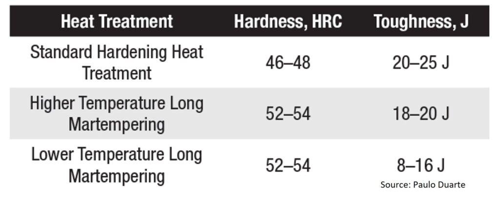
it is evident in at least H11 and H13 premium steel grades. This one day martempering treatment could potentially replace the traditional two- to three-day heat treatment cycle for large tools, offering significantly faster lead times and reduced energy consumption. Moreover, the mechanical properties achieved through long martempering are notable, as high levels of both hardness and toughness are obtained simultaneously, as demonstrated in Table 2.

Table 2. Mechanical properties of the new hardening process — long martempering

Industry 5.0

The integration of heat treatment equipment with management software enhances furnace utilization, quality control systems, and maintenance practices. Industry 5.0 can be implemented in heat treatment plants through the connection of databases that collect inputs from furnaces (e.g., temperature, time, pressure, heating elements, and auxiliary equipment performance) and production data (e.g., batch numbers, order details, operator
information, cycle setup, and load weight). This data is analyzed by software to generate valuable insights for plant management, process optimization, predictive maintenance, and quality control.

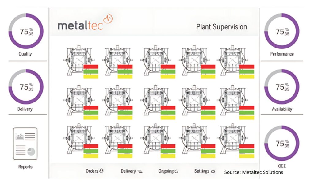
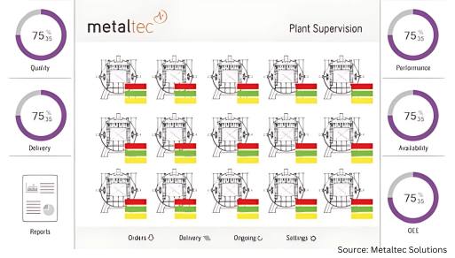
Figure 9. Heat treatment plant supervision solution

A supervision interface for a 5.0 solution can monitor furnaces and control them
remotely in real time (Figure 9). Operators receive updates on tasks, alerts, and production schedules. Additionally, plant productivity, efficiency, and maintenance
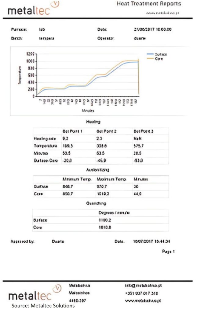
can be tracked through the same supervision software, whether on site or remote. Automatic reporting is also possible, enabling the approval or rejection of cycles based on criteria that are not typically used in heat treatment plants. This not only
improves quality but also facilitates process optimization and cost reduction.

Conclusion

Figure 10. Heat treatment quality automatic report including automatic approval

Acquiring a full understanding of furnaces in operation through data measurement and analysis allows full control over the heat treatment process. This facilitates process development, enabling cycle optimization and improvement in part quality. Additionally, testing and simulation practices can lead to cost reduction and shorter lead times.

The introduction of long martempering and Industry 5.0 will significantly enhance heat treatment processes, leading to improved delivery times and reduced operational risks. Automation and digitalization bring more data to the shop floor, improving plant management and resulting in greater efficiency, higher quality parts, and simplified task execution.

Finally, current personnel are busy with routine operations that are based on longestablished practices and may be limiting opportunities for innovation. Therefore, new teams or external consultants can be leveraged to focus on designing, studying, testing, and implementing each new heat treatment solution.

References

Fernandes, José, Laura Ribeiro, and Paulo Duarte. “Study of the Bainitic Transformation of H13 Premium Steel.” MSC thesis, Faculty of Engineering of Oporto University, 2021.

Figueiredo, Ana, Paulo Coelho, José Marafona, and Paulo Duarte. “Study of a Methodology for Selecting Standard Blocks for Hardening Heat Treatments.” MSC thesis, Faculty of Engineering of Oporto University, 2022.

Kind & Co. “Vacuum Hardening with Highest Levels of Precision.” Accessed January 30, 2025. https://www.kind-co.de/en/company/technologies/vacuum-hardening.html.

Maia, Pedro, Paulo Coelho, José Marafona, and Paulo Duarte. “Study of Heating Stage of Big Dimensions Steel Parts Hardening.” MSC thesis, Faculty of Engineering of Oporto University, 2013.

Metaltec Solutions. “Brochure Presentation.” Accessed January 30, 2025. https://www.metalsolvus.pt/en/wp-content/uploads/2019/01/plant-supervisionbrochure-V3.pdf.

Miranda, Isabel, Laura Ribeiro, and Paulo Duarte. “Heat Treatment of AISI H11 Premium Hot-Work Tool Steel.” MSC thesis, Faculty of Engineering of Oporto University, 2024.

Pinho, José Eduardo, Gil Andrade Campos, and Paulo Duarte. “Modelling and Simulation of Vacuum Hardening of Tool Steels.” MSC thesis, Aveiro University, 2017.

Ramada. “New Hardening Furnace up to 4 Tons.” Accessed January 30, 2025. https://www.ramada.pt/pt/media/noticias/novoforno-de-tempera-vacuo—ate-4-tons-.html.

Schmetz. “Schmetz Heat Treatment Furnaces.” Accessed January 30, 2025. https://edelmetal.com.tr/en/heat-treatmentfurnaces.

Schmetz. Sketch of the Cooling Process in the Vacuum Hardening Furnace: Schmetz Commercial Proposals Drawing – Metalsolvus Training Courses
Documentation.

Seco/Warwick. Vector 3D Hardening Furnace Commercial Brochure.

Solar Manufacturing. “Solar Vacuum Hardening Furnace.” Accessed January 30, 2025. https://solarmfg.com/vacuum-furnaces/horizontal-iq-vacuumfurnaces.

Wallace, J.F., W. Roberts, and E. Hakulinen. “Influence of Cooling Rate on the Microstructure and Toughness of Premium Grade H13 Die Steels.” Transactions of the 15th NADCA Congress (1989).

About the Author:

Paulo Duarte is a researcher and consultant on heat treat technologies. His education and expertise in metallurgy has culminated in several articles and patents. He was a former technical manager within bohleruddeholm group for the Portuguese market and heat treatment manager with the same group. Currently, Paulo efforts focus on helping heat treaters by providing innovative, more efficient, and profitable heat treatment services to companies.

For more information: Contact Paulo Duarte at paulo.duarte@metalsolvus.pt.


    Find heat treating products and services when you search On Heat Treat Buyers Guide.com


    Improving Hardening and Introducing Innovation for In-House Heat Treat Read More »
    Improving Hardening and Introducing Innovation for In-House Heat Treat

    Digital tools lead the way in vacuum hardening operations to ensure energy efficiency and processing repeatability. In this Technical Tuesday installment, Paulo Duarte, project manager at Metalsolvus, examines various advantages of wrought versus cast alloys in heat treat operations.

    This informative piece was first released in Heat Treat Today's March 2025 Aerospace print edition.


    Vacuum hardening has been the chosen process for hardening tools used in plastic injection, die casting, and metal sheet stamping over the past few decades. Although widely used and accepted, there is still room for improvement in tool performance through quality driven procedures. By employing easy methods of measurement, study, and testing, it is possible to enhance part integrity and mechanical properties, while simultaneously reducing heat treatment time and energy consumption. Advanced metallurgical analyses of heat treatment cycles and equipment can introduce better tools on the market, as well as provide time and cost saving heat treatments.

    Basics of Vacuum Hardening

    Figure 1. Cooling parts in vacuum hardening furnaces — inert gas injection on the hot chamber during cooling

    In vacuum hardening furnaces, temperature and time are carefully controlled at specific load locations to ensure optimal hardening. Optimal practices focus on heating and soaking the metal parts during heat treatment. The controlled introduction of vacuum and inert gases during the process ensures the right protective atmosphere for treatment, resulting in steel that is mainly free from oxidation and decarburization. This preserves the surface integrity of the tools.

    Cooling is achieved through the injection of an inert gas into the heating chamber, with controlled pressure and adequate recirculation between the heat exchanger and the hot zone (Figure 1). Different gas injection directions are utilized depending on the load being treated, ensuring optimal cooling.

    Hardening of Large Tools

    Figure 2. Large molds positioned inside the vacuum hardening furnace, two parallel cavities

    Heating and quenching large tools is one of the most challenging situations for vacuum hardening, as temperature control and part microstructure integrity are more difficult to obtain, which affects part quality. Large tools, typically made of hot work tool steels, are hardened in large furnaces. To minimize deformation, parts are preferably positioned vertically inside the furnace (Figure 2).

    Surface soaking times for big tools can significantly exceed
    standard austenitization and tempering times due to thermal gradients existing within the parts. Mold cores usually achieve the right soaking and tempering recommendation through accurate temperature control, monitored by well-positioned core thermocouples. A tool’s microstructure and performance will depend heavily on geometry, size, and temperature uniformity achieved during treatment. See Figure 3 for the core and surface typical hardening cycles for large tools.

    Figure 3. Heating and soaking cycle for the hardening of large tools (“Heat Treatment of a AISI H11 Premium Hot-Work Tool Steel”)

    The cooling phase is crucial in determining the final properties of both the surface and core of the tool. Higher gas injection pressures result in faster cooling and increased toughness, but this also introduces greater deformation risks, when directly cooled from austenitization temperature, so martempering done at low pressures is usually required.

    Balancing cooling pressure is one of the most secret topics in vacuum hardening. With a variety of parameters and procedures used among heat treaters, measuring and testing is essential for achieving consistent quality for better controlling the hardening process and attaining the best part quality.

    The use of higher or lower inert gas pressures directly affects the cooling rate, making it faster or slower, respectively. Regulating the gas injection pressure during the cooling phase significantly impacts the material’s toughness, even when cooling occurs within the bainitic-martensitic domain commonly observed in vacuum hardening practices. Faster cooling leads to finer microstructures, which in turn results in tougher materials. However, fully martensitic microstructures are rarely achieved in industrial vacuum hardening furnaces and are typically limited to smaller loads composed of small parts. In larger parts, the risk of pearlite formation increases, especially when cooling rates fall around 3°C/min (5°F/min) at the core, as illustrated in Figures 4 and 5.

    In industrial heat treatments of large tools, accurately monitoring core temperature is challenging, as it is difficult to position a thermocouple hole exactly at the innermost location or a nearby region. This makes it harder to control the hardening process and prevent pearlite formation. Therefore, studying the process to establish effective control measures is essential for achieving the highest possible
    quality.

    Figure 6. Mold temperature gradients during vacuum hardening: a) FEM mesh, b) gradients during heating at lower temperatures, c) gradients at the last pre-heating steps, and d) gradients during austenitization from Maia et al. “Study of Heating Stage of Big Dimension Steel Parts Hardening”; e) gradients during mold cooling from Pinho et al. “Modelling and Simulation of Vacuum Hardening of Tool Steels”

    Heat treatment simulation simplifies this task by allowing the hardening process to be predicted, with thermal gradients estimated and compensated through furnace control parameter adjustments. Figure 6 presents a real case study, where the temperature distribution inside a large mold was fully characterized during the entire heat treatment cycle using FEM (finite element method) simulation and validated through actual thermocouple measurements. FEM simulation, as a proven and highly effective technique for predicting heat treatment cycles, enables heat treaters to implement optimized, computer-supported heat treatment practices.

    Vacuum Hardening Standard Block Size and Cycle Forecast

    When working with loads composed of small to medium-sized parts, the core temperature of the load can be monitored using dummy standard blocks. These blocks have a central hole to accommodate the thermocouple used to control the heat treatment cycle. The dummy block should be selected to closely match the size of the largest part in the load. However, in commercial heat treatment settings, part sizes can vary widely, making it difficult to maintain a comprehensive set of dummy blocks that represents all possible heat treatment scenarios.

    Once again, simulation proves valuable in helping heat treaters gather useful data to anticipate the heat treatment cycle and determine the appropriate range of dummy blocks to have available on the shop floor. The procedure for selecting the dummy block range and forecasting the corresponding heat treatment times is outlined in the following equations. Ideally, the standard block should be made from the same material as the largest part in the load. If the materials differ, the characteristic length of the block can be calculated using the first of the equations to the right.

    Table 1 lists a range of proposed dummy block sizes to be used for monitoring the load temperature during heat treatment. The time to end of soaking at higher temperature is also given by Table 1 for a typical 600 x 600 x 900 mm hardening furnace. Times were obtained by FEM simulation and can be used to forecast the end of austenitization in a hardening process of each dummy block.

    Table 1. Proposed dimensional distribution range for cubic and cylindrical standard blocks and expected cycle times in a typical 600 x 600 x 900 mm hardening furnace (data from Figueiredo et al., “Study of a Methodology for Selecting Standard Blocks for Hardening Heat Treatments”)

    The simulated times were validated by using real parts temperature measurement by thermocouples. These were the calculated errors based on simulation and heat treat validation trial:

    Optimizing the Vacuum Hardening of Tools

    Figure 7. Effect of selecting different temperature (ΔT) range for starting to control the isothermal stage time. a) ΔT criteria and respective cycle time reduction; b) surface mechanical properties obtained by using different ΔT; and c) core properties after tempering at different ΔT range (Miranda et al., “Heat Treatment of a AISI H11 Premium Hot-Work Tool Steel,” MSC)

    FEM simulation can also be used to optimize the heat treatment process, but metallurgical testing remains crucial for providing reliable insights into safely reducing cycle time and energy consumption. Typically, for setting the isothermal stage time, a tolerance of -5°C relative to the temperature setpoint is used, leading to savings in both heat treatment duration and power consumption, as shown in Figure 7a. However, Figure 7b demonstrates that higher tolerance values (ΔT) can be considered. Tolerances of up to -10°C or even -20°C can be applied for controlling the soaking time without significantly affecting the hardness and toughness of the parts. Naturally, these results depend on the desired setpoints for the isothermal stages, but Figure 7c reflects the worst-case scenario for ΔT, referring to the use of lower austenitizing and tempering temperatures commonly applied in the hardening of hot-work tool steels.

    Future Trends of Vacuum Hardening

    Innovations like digitalization, automation, and resource reduction, as part of Industry 5.0 initiatives, are expected to drive advancements in heat treatment processes. Long martempering, a heat treatment under development for hardening hot-work tool steels, shows promise as an alternative to traditional quenching and tempering. This process offers a balance of high hardness and toughness in significantly less time, providing energy savings and faster turnaround.

    New Vacuum Hardening Process — Long Martempering

    Figure 8. New long martempering heat treatment cycle: AISI H13 premium toughness for two different long martempering temperatures (“Study of The Bainitic Transformation of H13 Premium Steel”)

    Long martempering is a heat treatment under development that can be used to harden hot-work tool steels. Long martempering is a process somewhat similar to austempering but is applied to steels rather than cast irons. Performed at temperatures within the martempering range, long martempering corresponds to an interrupted bainitic heat treatment with a specific process window (Figure 8) where high toughness is achieved at hardness levels exceeding those obtained through traditional quenching and tempering. Table 2 lists the mechanical properties attained for 5Cr hot-work premium tool steels.

    Table 2. Mechanical properties of the new hardening process — long martempering

    The transformation during long martempering is not yet fully characterized in terms of microstructure, however, curved needles of bainitic ferrite are observed without carbide precipitation. This phenomenon is generally not associated with steel but rather with ausferrite in cast irons. Nonetheless, it is evident in at least H11 and H13 premium steel grades. This one day martempering treatment could potentially replace the traditional two- to three-day heat treatment cycle for large tools, offering significantly faster lead times and reduced energy consumption. Moreover, the mechanical properties achieved through long martempering are notable, as high levels of both hardness and toughness are obtained simultaneously, as demonstrated in Table 2.

    Industry 5.0

    Figure 9. Heat treatment plant supervision solution

    The integration of heat treatment equipment with management software enhances furnace utilization, quality control systems, and maintenance practices. Industry 5.0 can be implemented in heat treatment plants through the connection of databases that collect inputs from furnaces (e.g., temperature, time, pressure, heating elements, and auxiliary equipment performance) and production data (e.g., batch numbers, order details, operator information, cycle setup, and load weight). This data is analyzed by software to generate valuable insights for plant management, process optimization, predictive maintenance, and quality control.

    A supervision interface for a 5.0 solution can monitor furnaces and control them remotely in real time (Figure 9). Operators receive updates on tasks, alerts, and production schedules. Additionally, plant productivity, efficiency, and maintenance can be tracked through the same supervision software, whether on site or remote. Automatic reporting is also possible, enabling the approval or rejection of cycles based on criteria that are not typically used in heat treatment plants. This not only improves quality but also facilitates process optimization and cost reduction.

    Conclusion

    Acquiring a full understanding of furnaces in operation through data measurement and analysis allows full control over the heat treatment process. This facilitates process development, enabling cycle optimization and improvement in part quality. Additionally, testing and simulation practices can lead to cost reduction and shorter lead times.

    The introduction of long martempering and Industry 5.0 will significantly enhance heat treatment processes, leading to improved delivery times and reduced operational risks. Automation and digitalization bring more data to the shop floor, improving plant management and resulting in greater efficiency, higher quality parts, and simplified task execution.

    Finally, current personnel are busy with routine operations that are based on long established practices and may be limiting opportunities for innovation. Therefore, new teams or external consultants can be leveraged to focus on designing, studying, testing, and implementing each new heat treatment solution.

    References

    Fernandes, José, Laura Ribeiro, and Paulo Duarte. “Study of the Bainitic Transformation of H13 Premium Steel.” MSC thesis, Faculty of Engineering of Oporto University, 2021.

    Figueiredo, Ana, Paulo Coelho, José Marafona, and Paulo Duarte. “Study of a Methodology for Selecting Standard Blocks for Hardening Heat Treatments.” MSC thesis, Faculty of Engineering of Oporto University, 2022.

    Kind & Co. “Vacuum Hardening with Highest Levels of Precision.” Accessed January 30, 2025. https://www.kind-co.de/en/company/technologies/vacuum-hardening.html.

    Maia, Pedro, Paulo Coelho, José Marafona, and Paulo Duarte. “Study of Heating Stage of Big Dimensions Steel Parts Hardening.” MSC thesis, Faculty of Engineering of Oporto University, 2013.

    Metaltec Solutions. “Brochure Presentation.” Accessed January 30, 2025. https://www.metalsolvus.pt/en/wp-content/uploads/2019/01/plant-supervision-brochure-V3.pdf.

    Miranda, Isabel, Laura Ribeiro, and Paulo Duarte. “Heat Treatment of AISI H11 Premium Hot-Work Tool Steel.” MSC thesis, Faculty of Engineering of Oporto University, 2024.

    Pinho, José Eduardo, Gil Andrade Campos, and Paulo Duarte. “Modelling and Simulation of Vacuum Hardening of Tool Steels.” MSC thesis, Aveiro University, 2017.

    Ramada. “New Hardening Furnace up to 4 Tons.” Accessed January 30, 2025. https://www.ramada.pt/pt/media/noticias/novo-forno-de-tempera-vacuo---ate-4-tons-.html.

    Schmetz. “Schmetz Heat Treatment Furnaces.” Accessed January 30, 2025. https://edelmetal.com.tr/en/heat-treatment-furnaces.

    Schmetz. Sketch of the Cooling Process in the Vacuum Hardening Furnace: Schmetz Commercial Proposals Drawing – Metalsolvus Training Courses Documentation.

    Seco/Warwick. Vector 3D Hardening Furnace Commercial Brochure.

    Solar Manufacturing. “Solar Vacuum Hardening Furnace.” Accessed January 30, https://solarmfg.com/vacuum-furnaces-horizontal-iq-vacuum-furnaces.

    Wallace, J.F., W. Roberts, and E. Hakulinen. “Influence of Cooling Rate on the Microstructure and Toughness of Premium Grade H13 Die Steels.” Transactions of the 15th NADCA Congress (1989).

    About The Author:

    Paulo Duarte, project manager at Metalsolvus, is a researcher and consultant on heat treat technologies. His education and expertise in metallurgy has culminated in several articles and patents. He was a former technical manager within bohler-uddeholm group for the Portuguese market and heat treatment manager with the same group. Currently, Paulo focus on helping heat treaters by providing innovative, more efficient, and profitable heat treatment services to companies.

    For more information: Contact Paulo Duarte at paulo.duarte@metalsolvus.pt.


    Improving Hardening and Introducing Innovation for In-House Heat Treat Read More »