Let’s discover new tricks and old tips on how to best serve air and atmosphere furnace systems. In this series, Heat Treat Today compiles top tips from experts around the industry for optimal furnace maintenance, inspection, combustion, data recording, testing, and more. Part 4, today's tips, examines carbon probes and carbon control. Look back to Part 1 here for tips on seals and leaks, Part 2 here for burners and combustion tips, and Part 3 here for data and record keeping tips.
This Technical Tuesday article is compiled from tips in Heat Treat Today's February Air & Atmosphere Furnace Systems print edition. If you have any tips of your own about air and atmosphere furnaces, our editors would be interested in sharing them online at www.heattreattoday.com. Email Bethany Leone at bethany@heattreattoday.com with your own ideas!
1. Slight Positive Pressures Are Best
Contact us with your Reader Feedback!
Atmosphere furnace pressure should be only slightly above ambient. The range should be between 0.25-0.35 inches water column. Higher pressures in multiple zone pusher furnaces will cause carbon control issues. High pressures in batch furnaces will cause high swings when doors and elevators move.
If you’re having atmosphere problems with a furnace that has been operating normally for some time, avoid the temptation to remove the carbon probe. There are several tests you can run on nearly all carbon probes while the probe is still in the furnace, at temperature, in a reducing atmosphere. Super Systems Inc. provides an 11-step diagnostic procedure in a white paper on their website, in a paper titled, “Carbon Sensor Troubleshooting” by Stephen Thompson.
"Review process date for abnormalities." Source: Super Systems Inc.
Many factors can contribute to why parts are not meeting the correct hardness readings. According to Super Systems Inc., here is a quick checklist of how to start narrowing down the culprit:
Review process data for abnormalities. The first thing to do is make sure the parts were exposed to the right recipe. Check the recorders to make sure the temperature prof le and atmosphere composition were correct. Make sure all fans and baffes were working correctly. Determine if any zones were out of scope and that quench times were acceptable. If any red flags appear, hunt down the culprit to see if it may have contributed to soft parts.
Check the generator. Next, check the generator to make sure it is producing the gas composition desired for the process. If available, check the recorders to make sure the gas composition was on target. If not, check the generator inputs and then the internal workings of the generator.
Check the furnace atmosphere. If the generator appears to be working correctly, the next step would be to check the furnace itself for atmosphere leaks. Depending on what type of furnace you have, common leak points will vary; for continuous furnaces, common leak points are a door, fan, T/C, or atmosphere inlet seals. Other sources of atmosphere contamination may be leaking water cooling lines in water-cooled jackets or water-cooled bearings. More than likely, if the generator is providing the correct atmosphere but parts are still soft, there is a leak into the furnace. This will often be accompanied by discolored parts.
Check carbon controller to make sure it matches furnace atmosphere reading (verify probe accuracy and adjust carbon controller). This can be done using a number of different methods: dew point, shim stock, carbon bar, three gas analysis, coil (resistance), etc. Each of these methods provides a verification of the furnace atmosphere which can be compared to the reading on the carbon controller. If the atmosphere on the carbon controller is higher than the reading on the alternate atmosphere check, that would indicate the amount of carbon available to the parts is not as perceived. The COF/PF on the carbon controller should be modified to adjust the carbon controller reading to the appropriate carbon atmosphere. If the reading is way off, it may require the probe to be replaced.
Let’s discover new tricks and old tips on how to best serve air and atmosphere furnace systems. In this series, Heat Treat Today compiles top tips from experts around the industry for optimal furnace maintenance, inspection, combustion, data recording, testing, and more. Part 3, today's tips, examines AI and record keeping. Look back to Part 1 here for tips on seals and leaks and Part 2 here for burners and combustion tips.
This Technical Tuesday article is compiled from tips in Heat Treat Today's February Air & Atmosphere Furnace Systems print edition. If you have any tips of your own about air and atmosphere furnaces, our editors would be interested in sharing them online at www.heattreattoday.com. Email Bethany Leone at bethany@heattreattoday.com with your own ideas!
1. Use AI To Simplify Your Maintenance
Contact us with your Reader Feedback!
"cloud view of heat treating operation" Source: NITREX
Simplify your maintenance! Today, using artificial intelligence (AI) software allows the “Cloud” to do the hard work. NITREX has introduced QMULUS, a web-based software solution, with each of its nitriding systems, which examines key parameters to determine if your furnace is having any issues. Gas flows, amperage, motors, and cycles are all monitored for health factors. But QMULUS is so much more than that. It also analyzes input usages and calculates the cost of each run; logs all data relevant to running processes more efficiently; and provides an easy and seamless cloud view of heat treating operations.
This is a very simple tip that is often overlooked when customers are focused on meeting production goals instead of the maintenance of their equipment. It is critical to record the operating settings of their furnace systems when parts are coming out at their best, or simply before issues arise. When something goes awry in the process and troubleshooting is required, service technicians hear all too often that there is no record of what the ideal or correct setpoints are for various systems. Nearly every item on a modern heat treating furnace (or in its control panel) has a setpoint or position that can be recorded or physically marked. Now, clearly some items are more critical than others when it comes to air and atmosphere settings. Below are a few items you’ll want to have setpoint/positioning records of before they require troubleshooting:
Flowmeter setpoints (at the furnace and generator)
Blower/pump/motor VFD setpoints (primarily frequency setpoints and ramp rates)
Manual or actuated damper positions on flues
Regulator setpoint (from pressure gauge or in-line test port)
High/low pressure switch setpoints
Any air/gas/atmosphere ratios for various recipe steps
Burnout frequency and duration (if applicable)
An added incentive to record these settings is the preventative maintenance benefit. The best way to avoid supply chain issues and delivery delays is to fix a problem before it grows into a bigger issue. When a setpoint/setting is correct but product quality begins changing, it is a warning sign that consumables may be approaching end of life (such as nickel catalyst in endothermic gas generators) or components require maintenance (such as air inlet filter replacements).
Let’s discover new tricks and old tips on how to best serve air and atmosphere furnace systems. In this series, Heat Treat Today compiles top tips from experts around the industry for optimal furnace maintenance, inspection, combustion, data recording, testing, and more. Part 2, today's tips, examines burner and flame safety. Look back to Part 1 here for tips on seals and leaks.
This Technical Tuesday article is compiled from tips in Heat Treat Today's February Air & Atmosphere Furnace Systems print edition. If you have any tips of your own about air and atmosphere furnaces, our editors would be interested in sharing them online at www.heattreattoday.com. Email Bethany Leone at bethany@heattreattoday.com with your own ideas!
1. Operating with a Multiple Burner System
Contact us with your Reader Feedback!
If a furnace or oven has a multiple burner combustion system with only one valve train, a multi-burner combustion safeguard should be used. This ensures that if one burner fails, they all go out.
Source: Bruce Yates, "Ten Tips for Safeguarding Combustion Processes"
#multiburner #combustion #safety
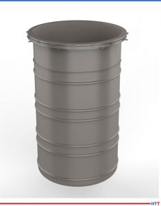
2. Regularly Inspect Retort Alloys
Source: Nitrex
Retort alloys must be inspected on a regular basis. Hot spots can be identified by bulges. Plastic deformation occurs due to overheating, causing the hotter section to bulge because it is surrounded by stronger metal. Inspect your retorts or radiant tubes for deformations. In addition, constant thermal cycling can cause problems with some alloys. Look for cracks in welds or near welds. Some leak detection methods can also detect alloy issues or overheating.
Localized overheating could indicate a problem with the burner or the heating element. Early detection and correction can save you a lot of money on expensive alloys.
Flame supervision may be defined as the detection of the presence or absence of flame. If a flame is present during the intended combustion period, the supervisory system will allow a fuel flow to feed combustion. If the absence of flame is detected, the fuel valves are de-energized.
This basic definition does not consider the hazard potential during startup or ignition, however. A dangerous combustible mixture within a furnace or oven consists of the accumulation of combustibles (gas) mixed with air, in proportions that will result in rapid or uncontrolled combustion (an explosion). It depends on the quantity of gas and the air-to-fuel ratio at the moment of ignition.
Source: Bruce Yates, "Ten Tips for Safeguarding Combustion Processes"
#flamedetection #combustion #valves
4. Remember that Flame Safety Starts with Purging
The sequence for flame safety starts with purging the furnace or oven. Purge time should allow for four air changes.
Fuel valves can — and do — leak gas. The purpose of purging is to remove combustible gases from the combustion chamber before introducing an ignition source. The four air changes in the combustion chamber are based on a worst-case scenario that includes having a burner chamber that is completely filled with gas.
Once airflow for purge is verified, the proof-of-valve closure is confined and safety limits are proven. Then the purge timer — which may or may not be integral to the combustion safeguard — determines the period of time required to evacuate the combustion chamber.
Source: Bruce Yates, "Ten Tips for Safeguarding Combustion Processes"
N2: It’s so harmless, it makes up the majority of the air we breathe. But, once bonded with oxygen, the resulting compound can be dangerous to the environment and public health; as heat treaters know, keeping nitrogen oxide production levels low is a key part of complying with government requirements. When it comes to reducing nitrogen oxide levels, what options do heat treaters have?
This Technical Tuesday article written by Robert Sanderson, director of Business Development at Rockford Combustion, first appeared in Heat Treat Today's August 2022 Automotiveprint edition.
Robert Sanderson Director of Business Development Rockford Combustion
Nitrogen oxides (NOx) are a collection of highly reactive chemical compounds formed during combustion processes, partly from nitrogen compounds in the fuel, but mostly by direct combination of atmospheric oxygen and nitrogen in flames. One chemical reactant of NOx is nitrogen gas (N2). Formed by two nitrogen atoms, N2 lacks smell, color, and taste. N2 is also non-flammable and inactive at room temperature. In fact, N2 makes up 78% of our atmosphere, underscoring how little danger the compound, by itself, represents in the environment.
Contact us with your Reader Feedback!
However, when N2 reacts with oxygen (O), an assortment of nitrogen oxides such as nitric oxide (NO) and nitrogen dioxide (NO2) can be formed. All forms of the nitrogen oxides taken together are referred to as NOx, with the measurements reported as equivalent to NO2. NOx formation can happen naturally such as during a lightning strike, biogenetically in agricultural fertilizer, or from fossil fuel powered cars (mobile) and industrial combustion systems (stationary). Combustion processes that form NOx by-products predominately create them as both NO and NO2.
In this article we will look at NOx formed from combustion processes, why NOx is dangerous both to the environment and public health, and what options operators of industrial combustion systems have to reduce NOx emissions in equipment fi red by natural gas, oil, or coal. We will also show how reducing NOx in certain combustion systems can increase energy efficiency to bolster return on investment.
NOx
As a pollutant, NOx represents a serious threat to human health and the environment. When NOx is mixed with organic compounds under UV light it will create reddish-brown smog (ozone). Smog that envelops cities during the summer often degrades air quality and can irritate lung tissue. Additionally, NOx has been linked to acid rain and high levels of NOx have been shown to damage ecosystems by making vegetation more susceptible to disease and frost damage.
During the 1990s, the use of natural gas in industrial combustion processes displaced coal and oil. This has led to a significant reduction in NOx emissions. At the same time, local and federal requirements grew increasingly stringent, including the Clean Air Act Amendments of 1990 that required major stationary sources of NOx to install and operate reasonably available control technology (RACT). Current regulations in some parts of the country are focused on NOx levels of 9 ppm (parts per million) or lower. Manufacturers have responded to these challenges by introducing ever-lower NOx capable burners and NOx control schemes.
What Are the Types of NOx
As mentioned, whenever fossil fuel is burned, NOx can be formed. For that reason, motor vehicles by their sheer numbers are major contributors to NOx pollution. However, for the purpose of this article, we are narrowing the focus exclusively on NOx emitted by fuel-fired industrial combustion systems, such as boilers, furnaces, heaters, ovens, kilns, and dryers. NOx formed in high-temperature industrial systems can be broken down into three types: Fuel NOx, Thermal NOx, and Prompt NOx.
Fuel NOx
Although natural gas is typically free of fuel-bound nitrogen, nitrogen is often found in liquid and solid fuels. When nitrogen that is chemically bonded into fuel molecules is combusted, it directly converts to Fuel NOx. In fact, untreated fuel oil can contain as much as 1,000 ppm of fuel-bound nitrogen resulting in over 40 ppm NOx in exhaust. Ammonia (NH3) combustion is particularly difficult as it is essentially all fuel-bonded nitrogen, and fully converts to Fuel NOx. Hydrogen (H2) fuel combustion has no fuel-bound nitrogen and produces no Fuel NOx.
Thermal NOx
Sometimes called Zeldovich NOx, after the Russian physicist, Thermal NOx forms when airborne nitrogen and oxygen merge in high temperature zones. Thermal NOx constitutes most of the NOx formed during the combustion of gases and light oils. The formation of Thermal NOx is highly temperature dependent — basically the hotter the combustion the more Thermal NOx is formed. Thermal NOx generally begins to occur at about 1600°F, with formation rates escalating as the temperatures increase above this. But the formation of Thermal NOx is also dependent on pressure and residence time. Decreasing any of these three factors reduces Thermal NOx levels. Here, it is important to note that while natural gas is a cleaner burning hydrocarbon, all flames (including those of pure hydrogen) release heat. And any high temperature heat release has the potential to produce Thermal NOx. Many common Thermal NOx treatments utilize various methods to minimize temperatures in the hottest areas of the flame.
Prompt NOx
In 1971, Charles Fenimore proposed the concept of Prompt NOx. Prompt NOx occurs when N2 fuses with partially combusted fuel products early in a combustion process. Basically, Prompt NOx is the “leftover” NOx when both Thermal and Fuel NOx are accounted for. Although Prompt NOx represents a miniscule fraction of overall NOx in a combustion system, that fraction becomes in ever-greater proportion as other NOx control mechanisms are introduced. Prompt NOx is not thermally dependent which makes it difficult to design for. As such, it is often perceived as a source that cannot be easily controlled, hence suppression eff orts focus on reducing Thermal and Fuel NOx.
Why Is NOx Controlled?
Nitrogen oxides emitted into our atmosphere lead to increased air pollutants that irritate airways in the human respiratory system, among other health problems. Of course, air pollution impacts everyone but some of us are more susceptible: young children and seniors, those with asthma, and people working outdoors, for example. Even brief exposures to NOx can aggravate respiratory diseases, particularly asthma, emphysema, or bronchitis, leading to coughing, wheezing, difficulty breathing, and hospital admissions. Long-term exposure to elevated concentrations of NOx may contribute to the development of asthma and potentially increase susceptibility to respiratory infections.1 A 2012 United Kingdom study concluded that air pollution related deaths were more than double those of traffic accidents.2 A related study in the United States came to similar conclusions.3
The key problem is ozone. When exposed to UV rays in sunlight, NOx molecules interact with volatile organic compounds (VOC) to form ground-level or “tropospheric” ozone (O3), also known as smog. Smog can damage lung tissue, and it is especially dangerous to people with respiratory illnesses that may experience more intense attacks. Ozone is also hard on plants and animals, damaging ecosystems and leading to reduced crop and forest yields. In the United States, ozone accounts for an estimated $9 billion in reduced corn and soybean production annually.4 It also kills many seedlings and damages foliage, making trees more susceptible to diseases, pests, and harsh weather. Finally, ozone acts as a powerful greenhouse gas, albeit much shorter lived than carbon dioxide.
In the presence of water droplets, nitrogen oxides form nitric acid, contributing to the problem of acid rain. Additionally, NOx deposition in the oceans provides phytoplankton with nutrients, worsening the issue of red tides and other harmful algal blooms. A closely related molecule can be created, nitrous oxide (N2O), another greenhouse gas that plays a role in climate change.
Abating NOx Emissions
In response to stringent environmental regulations, the combustion industry has made important strides in reducing combustion associated NOx, while simultaneously furthering energy efficiency. These steps include a host of new and emerging technologies and practical, proven operational tactics, like the following:
Fuel Switching
One simple method to reduce Fuel NOx emissions is to switch from a high nitrogen-bound content fuel to a fuel with reduced nitrogen content such as another distillate oil, or natural or hydrogen gas — which are essentially nitrogen free fuels. Changing fuels may necessitate changes to burners, fuel trains, and burner management systems as the alternate fuel will likely have different combustion characteristics and chemical properties.
Natural Gas Reburning (NGR)
NGR has proven to yield NOx reduction up to 75% from standard burners. NGR involves building a “gas-reburning zone” on top of the primary combustion zone where natural gas is injected. A fuel-rich region is created where NOx reacts to hydrocarbon radicals and molecular nitrogen is formed. This technique can be built into some burner designs as an integral operating property. Burners that use this NOx reduction method must be carefully sized and examined for operating inputs as their performance ranges are often restricted.
Low NOx Burners
Low NOx and Ultra-Low NOx burners have been shown to reduce emissions by up to 50% compared to standard burners. Greater reduction efficiencies can be achieved by combining the burner with flue gas recirculation (FGR, see below). Low NOx burners reduce peak flame temperature by combinations of induced recirculation zones, staged or delayed combustion zones, and reduced local oxygen concentrations. Downsides of these mechanisms are that these designs are typically more expensive than conventional burners, often require a larger footprint, and they may necessitate extensive furnace modifications. These solutions are popular with volumetric air heating and low temperature combustion processes.
Reduced Oxygen Concentration
Under certain conditions NOx emissions will diminish in a near linear fashion with decreasing excess air. Decreasing the extraneous available oxygen in the combustion zone lengthens the flame, resulting in a slower heat release rate per unit flame volume. Keep in mind that if excess air falls below a threshold value, combustion efficiency may decrease due to incomplete mixing. This is a popular method of NOx control on tube fired burners, reducing furnaces, and other applications where combustion air is fully isolated from the process, allowing for precise management of oxygen levels.
Steam/Water Injection
As we discussed earlier, lowering the local oxygen concentration will slow combustion and reduce developed flame temperature, therefore decreasing the formation of Thermal NOx. One method to achieve this result is to inject a small amount of water or steam into the vicinity of the flame. The water will absorb heat as steam is formed, which lowers the flame temperature. Additionally, the steam displaces the available oxygen, which slows the rate of combustion and further lowers the flame temperature. This method is effective, but generally lowers the combustion efficiency by 2% as the water molecules absorb some of the thermal energy. The effects of trace minerals in the water should also be considered.
Selective Catalytic Reduction (SCR)
Ultra-Low NOx emissions (sub-5 ppm NOx requirement) are achieved with the use of selective catalytic reduction (SCR) technology. SCR is a post-combustion method that involves injecting an ammoniacal reagent such as ammonia, aqueous ammonia, or urea in the presence of a catalyst to convert NOx to harmless nitrogen and oxygen in the exhaust gasses. Ammonia-free solutions utilizing urea are an option for users averse to handling and storing ammonia. It is not unusual for an SCR unit to reduce incoming flue NOx levels from 30 ppm to below 5 ppm, or by upwards of 95% reductions of higher inlet concentrations. And they can lower the electrical load by reducing fan requirements compared to flue gas recirculation. Catalyst costs have steadily dropped since SCR’s introduction in the 1960s, yet transaction expenses generally make SCR a costly NOx reduction strategy. A common issue is ammonia breakthrough that can occur when excess reagent for various reasons “slips” past the catalyst unreacted. Some jurisdictions have limits not only for NOx emission limits but also for ammonia slip, complicating the use of SCR as an abatement strategy.
Selective Catalytic Reduction with Economizers
Incorporating an extended-surface economizer with SCR delivers low NOx emissions and higher system efficiency, lowering operational costs. The SCR is the first phase of the system, converting NOx to nitrogen and oxygen. The second phase is a finned tube economizer, capturing and redirecting wasted heat back via heat transfer to feedwater or makeup water. Increasing efficiency by one or two percentage points can amount to measurable cost savings. Users of this two-phase system also report higher turndowns (the ratio of maximum to minimum firing rate), more stable flames, and faster response times to load swings.
Flue Gas Recirculation (FGR)
FGR (5 ppm to 20 ppm NOx requirement) is a well-attested, pollution-reducing technology that reduces thermal NOx by decreasing the burner flame temperature and slows the combustion reaction. In the FGR process, a portion of flue gases generated during combustion is redirected to the burner with fresh air, which helps to cool down the flame’s peak temperature and slows combustion reactions, thereby reducing the formation of NOx. One downside of FGR is that flue gas recirculation requires electrical energy for additional air handling. Another issue is that not all thermal processes can use FGR, for example, if the flue gases are too hot or too high in oxygen.
Benefits of NOx control technologies range from lowering your business’s carbon footprint to maximizing fuel efficiency. When it comes to reducing nitrogen oxide levels, selection of options will depend on your thermal processing systems, site-specific conditions, and regulatory and economic considerations. With so many ways to control NOx levels, heat treaters can choose the option that works best for them.
References
[1] “Basic Information about NO2,” EPA.gov, United States Environmental Protection Agency, June 2022, https://www.epa.gov/no2-pollution/basic-information-about-no2.
[2] Roland Pease, “Traffic pollution kills 5,000 a year in UK, says study,” BBC.com, BBC News, June 2022, https://www.bbc.com/news/science-environment-17704116.
[3] Fabio Caiazzo et al. “Air pollution and early deaths in the United States. Part I: Quantifying the impact of major sectors in 2005,” Atmospheric Environment 79 (2013): 198-208, June 2022, https://www.sciencedirect.com/science/article/abs/pii/S1352231013004548.
[4] Justin M. McGrath et al, “An analysis of ozone damage to historical maize and soybean yields in the United States,” June 2022, https://www.pnas.org/doi/10.1073/pnas.1509777112.
About the Author: Throughout Robert’s 32+ years of experience within the combustion field, he has been involved in the automotive, abatement-oxidation, aerospace, agriculture, food and beverage, HVAC, heat treating, glass, asphalt, pyrolysis, reducing furnaces, dryers, immersion heaters, and power generation industries. He has formerly worked with Eclipse, Honeywell, and Haden, Inc. and now brings systems integration, as well as the application experience of how systems interact in various environments to Rockford Combustion as the director of business development. Robert is a member of the NFPA-86 technical committee.
Find heat treating products and services when you search on Heat Treat Buyers Guide.com


 Find heat treating products and services when you search on Heat Treat Buyers Guide.com