heat treat combustion

Improving Your Use of Radiant Tubes, Part 4

op-ed

In previous months, this series has explored the geometry of a tube, why radiant tubes matter, what happens inside the tube, and radiant tube control systems. For the first three installments, check out Heat Treat Today’s digital editions in November 2022, December 2022, and February 2023. For the month of May, we will continue our discussion of different modes of control for radiant tube burners.

This column is a Combustion Corner feature written by John Clarke, technical director at Helios Electric Corporation, and appeared in Heat Treat Today’s May 2023 Sustainable Heat Treat Technologies print edition.

If you have suggestions for radiant tube topics you’d like John to explore for future Technical Tuesdays, please email Bethany@heattreattoday.com.


John B. Clarke
Technical Director
Helios Electric Corporation
Source: Helios Electric Corporation

High/low and on/off controls require different control strategies from a proportional mode of control. In all cases, we assume the temperature control will be provided by a proportional-integral-derivative loop (PID loop). The function can be provided by a stand-alone instrument or a PID function in a programmable or process controller. The PID algorithm looks not only at the temperature of the process as indicated by the control element (thermocouple or RTD) and compares it to the setpoint — but it also considers the offset and rate of change as well. When properly tuned, a PID control loop can provide control accurate enough to match the process (actual) temperature to the setpoint within a degree or two.

For the lay person, another way of describing a PID loop is to consider how a driver regulates the speed of his automobile. Assume you are driving and want to catch up with and follow the car ahead of you — to do so, you need to match that car’s speed and maintain a safe distance. What you don’t do is floor the automobile until you get to the desired following distance and then hit the brakes. What you do is first accelerate to a speed faster than the target car to close the gap, then you instinctively take your foot off the accelerator when you get close, slowing gradually until your speed and position are as you desire. In this example, you have considered your speed, how close you are to the car you are attempting to follow, and the rate at which you are closing the gap. A PID loop is nothing more than a mathematical model of these actions.

The PID control loop provides an output — the format can vary, but it is in essence a percent output. It is a percent of the maximum firing rate the system needs to provide to achieve and maintain the desired furnace temperature. This percent output can be translated directly into a proportional output for proportional control — where the firing rate is proportional to the loop’s output.

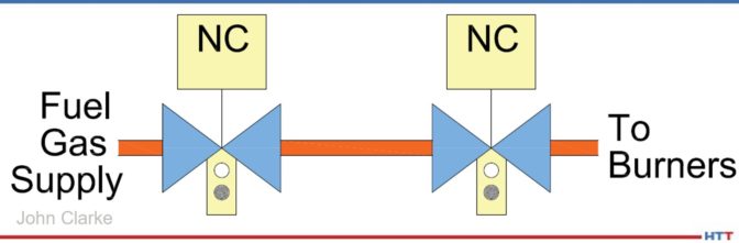
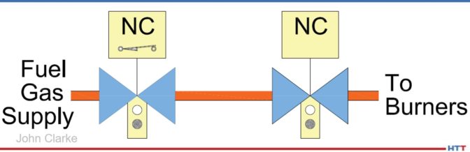
On/off or high/low controls require a different approach where a time proportioning output is provided in which the burner fires on and off on a fixed time cycle. In this mode of control, the PID loop’s output is multiplied by the cycle time to determine the on or high fire period and the on or high fire time is subtracted from the cycle time to determine the off or low fire period. Cycle times can run from as little as 30 seconds to as much as a few minutes. Obviously, the shorter the cycle time, the more responsive the control, but also the more wear on the control components. The cycle time should be as long as possible but still meet the needs of the process control.

Don’t confuse these pulses with other control methods that are marketed as pulse firing. When people speak of pulse firing, they often mean a pattern with alternate burners firing to provide greater temperature uniformity and heat transfer. This is a very interesting subject and the topic for another day.


Find heat treating products and services when you search on Heat Treat Buyers Guide.com


Improving Your Use of Radiant Tubes, Part 4 Read More »

Improving Your Use of Radiant Tubes, Part 3

op-ed

Over the last several months, the Combustion Corner series has challenged readers to spend some time researching opportunities to improve their use of radiant tubes — their performance, efficiency, and uniformity. So far, the series has explored the geometry of a tube, why radiant tubes matter, and what happens inside the tube. When it comes to radiant tube systems controls, what are your options? Read on to learn about the three modes of control.

This column is a Combustion Corner feature written by John Clarke, technical director at Helios Electric Corporation, and appeared in Heat Treat Today’s February 2023 Air & Atmosphere Furnace Systems print edition.

If you have suggestions for savings opportunities you’d like John to explore for future columns, please email Karen@heattreattoday.com.


John B. Clarke
Technical Director
Helios Electric Corporation
Source: Helios Electric Corporation

This month we will discuss the various modes of control that can be applied to radiant tube systems. We will consider three typical modes of control: on/off, high/low, and proportional control.

When a radiant tube is operated in an on/off mode, the burner is fired full on or completely off. Using this mode of control, the burner must be relit at the start of each cycle. The advantage of this mode of control is that the on firing rate can be optimized to provide optimum heat transfer, and when the burner cycle is off, the tube will idle. If the pulses are rapid enough, there is very little cyclical variation in temperature. The heat capacity (stored heat) of the radiant tube provides a flywheel effect to smooth out the temperature swings between on and off periods. The drawback of this mode of control is that the ignition system, most commonly a spark plug, is energized frequently, loading the transformer and wearing material off the spark plug and the valves that control the air and fuel are cycled frequently. If the cycle time is one minute — the burner must relight, and the valves must cycle over 500,000 times a year. Care must be taken to ensure the components used in this system are rated to survive this demand.

Another mode of control is high/low firing. With this mode of control, the burner cycles between the high firing rate and low firing rate, but instead of shutting down completely, the burners are returned to a low firing condition. In this mode of control, care must be taken to ensure the low firing rate does not overheat the firing leg of the radiant tube. Other than that, this mode of control is very similar to on/off control.

The last mode of control is fully proportional. In this mode of control, the burner fires between 0 and 100 percent of the maximum output depending on the burner demand. The air can be adjusted using a proportional valve or by varying the combustion air blower speed using a variable frequency drive, or in some cases, both. The fuel gas is regulated by a proportional valve or a regulator that matches the output pressure to an impulse or control  pressure. Using this mode, the burner fires more or less on ratio (with a consistent level of excess air), or some systems will increase the excess air at low fire to ensure clean combustion and to reduce the available heat at low fire. When a burner has higher levels of excess air, more energy is used to heat the air not used to burn the gas; therefore, less energy is available to heat the furnace chamber. This provides greater turndown (the difference between high and low firing).

Which method is best for a given furnace? That is impossible to say without considering the burner type and geometry of the radiant tube used in the furnace. All three methods can provide good uniformity and efficiency, provided it is appropriate for the equipment in question. In fact, there are applications that blend proportional with high/low firing to meet very specific needs. These systems simply alter the maximum — or high — firing rate to better meet the systems’ requirements.

Again, the control approach is a function of the burner, the radiant tube, and the application. There is really no one-size-its-all; each application must be approached with an open mind. The next column will address the role of heat recovery to efficiency in greater detail.


Find heat treating products and services when you search on Heat Treat Buyers Guide.com


Improving Your Use of Radiant Tubes, Part 3 Read More »

How to Lower the Cost of Operating Your Burner System

We continue to consider the topic of natural gas pricing and reduction and its impact on heat treaters. Much of the discussion in this month’s article initially appears to deal with process quality or consistency. But understand, process consistency and energy savings are inextricably linked.

This Technical Tuesday column appeared in Heat Treat Today’s December 2021 Medical and Energy print editionJohn Clarke is the technical director at  Helios Electric Corporation and has written about combustion related topics throughout 2021 for Heat Treat Today.

In February 2022, we will continue this series. Please forward any questions or suggestions to our editor Karen@heattreattoday.com.


John B. Clarke
Technical Director
Helios Electric Corporation
Source: Helios Electrical Corporation

No matter what method we pursue to save natural gas, it is safe to assume it will require some investment — time and/or materials. Furthermore, we want a payback from this investment. To calculate the payback, we need to estimate the cost of the project as well as the value of the natural gas saved. We can generally nail down the cost of a project by obtaining quotes for materials and labor, but it is more difficult to know what the future cost of natural gas will be; and without knowing the savings, the payback is at best an educated guess.

As we have discussed in previous articles, demand for North American natural gas is increasing for electrical power generation as well as liquified natural gas (LNG) export to areas in the world with limited supplies. These are steady, predictable demands and less susceptible to seasonal variations in temperature. Less heating demand during warmer winters is generally offset by greater electrical power generating demands during warmer summers.

Let us revisit recent trends in the cost of natural gas. The graph below depicts the spot price for 22 consecutive trading days ending November 2, 2021.

Figure 1. Henry Hub price for natural gas

Beware of the displaced origin on the graph below — it makes the fluctuations in the spot price appear greater than they are, but it is done to indicate a range of prices — generally around $5.50/mmBTU. (Once again, neither the author nor Heat Treat Today presents the opinion of future prices for any purpose other than to further our discussions of energy saving project paybacks.)

Last month, we posed three questions:

  1. How do I know when the material I am heating is at the desired temperature?
  2. Do I have excessive factors of safety built into my process to compensate for not knowing the temperature at the core of the part being heated?
  3. How much fuel can I save with a shorter cycle?

Much of the discussion in this month’s article initially appears to deal with process quality or consistency. But understand, process consistency and energy savings are inextricably linked.

What temperature is my furnace or oven?

You walk up to the controls and read 1650°F. Is that the temperature of your oven? The answer is a definite “maybe” because the temperature displayed on a single loop temperature controller is simply the reflection of the small voltage generated by one thermocouple. This is obvious, or else we wouldn’t need to run temperature surveys. But the question is — do we have to live with this shortcoming? The answer to this question is a definite “no”! Modern control instrumentation makes it easy to use many thermocouples to sense the temperature of the furnace throughout the chamber. Then take the mean of these values to calculate the temperature and use this average value for the input to our temperature control loop. By comparing the readings of temperatures at various points in the furnace chamber, we can sense if all the work being heated is near to the desired setpoint.

No furnace load is perfect — there is always some non-uniformity of mass or surface area. With multiple sensing points, the more massive and slower to heat portion of the load will influence the nearest thermocouple. The furnace control can be designed to hold until the coolest thermocouple in the chamber reaches some minimum temperature. Perhaps this is now the trigger for a soak timer.

In addition to measuring multiple chamber temperatures and inferring the actual temperature of the work, the proportional integral derivative, or PID, temperature control algorithm provides a good deal of insight as to how close the work is to the desired furnace temperature. All PID controllers or programmed functions provide an output value. For our discussions, we will assume the output is between 0-100%. This output is used to control the heating element(s) of burners’ input levels. The advantage of the PID loop is that it calculates the required value more rapidly than a conventional on/off control — providing us the near steady values for our furnace temperatures.

Let’s imagine we adjust the temperature setpoint of our empty furnace to 1650°F. We will allow it to come to temperature and wait an hour until it is soaked out, so that the refractory and internal components are at some steady state temperature. The PID loop will settle to some average value; we will assume this value is 35%, which represents the holding consumption of the furnace. The heat entering the furnace is in equilibrium with the heat being lost through the refractory, up the flue, around the door, etc.

Now we load the furnace with 4000 pounds of thick steel parts, where the mass/surface area ratio is very high. The furnace thermocouple(s) will reach 1650°F in one hour; but, if we look at the PID loop output, it will take time for it to fall to 35%. The time between the indicated 1650°F and the output falling to 35% is a period when the work continues to absorb heat and conduct it to its core. When the output stabilizes at 35%, we know the work is soaked out at temperature — in other words, the surface and core of the parts are at the furnace setpoint temperature.

Do I have excessive factors of safety built into my process to compensate for not knowing the temperature at the core of the part being heated?

With added insight into the actual temperature of the work being heated, excessive soak times can be reduced without risk. It also allows for the running of light and heavy loads with the same program.

How much fuel can I save with a shorter cycle?

Building on the same hypothetical; assume the input to this furnace is 4,000,000 BTU/Hr and 1,000 hours are saved per year — the savings will be roughly 4,000,000 BTU/Hr x 0.35 (holding consumption) x $5.50/mmBTU x 1,000 Hours per year, or $7,700/year. Now, perform this modification on four furnaces. Add to this savings the increased confidence that the work is at temperature before the soak period is initiated, better consistency for varying part loading, and I think we can agree — we have a project. The only question is, will we cash the check?

About the Author:

John Clarke, with over 30 years in the heat processing area, is currently the technical director of Helios Corporation. John’s work includes system efficiency analysis, burner design as well as burner management systems. John was a former president of the Industrial Heating Equipment Association and vice president at Maxon Corporation.

How to Lower the Cost of Operating Your Burner System Read More »

Nuts and Bolts of Combustion Systems – Safety Shutoff Valve

op-edSafety shutoff valves are the last line of defense against a potentially catastrophic incident. When conditions require, they interrupt the flow of fuel to the burner(s) and oven. There are many options when selecting fuel safety shutoff valves for your application. The construction and application of these devices is highly regulated by interlocking standards created by many different organizations. The goal of this article is to clarify how to comply with the most common standard affecting the reader: NFPA 86.

This column appeared in Heat Treat Today’s 2021 Trade Show September print editionJohn Clarke is the technical director at  Helios Electric Corporation and is writing about combustion related topics throughout 2021 for Heat Treat Today.


John B. Clarke
Technical Director
Helios Electric Corporation
Source: Helios Electric Corporation

To start, we must define our terms. The 2019 edition of NFPA 86* defines a safety shutoff valve as a “normally closed valve installed in the piping that closes automatically to shut off the fuel, atmosphere gas, or oxygen in the event of abnormal conditions or during shutdown.”1 A valve is “normally closed” (NC) if it closes automatically when power is removed. A furnace or oven typically has as few as two or more safety shutoff valves. [Author’s note: If the system uses radiant tubes for heating, and all the criteria are met, it may be acceptable to use only one valve in series, but this exception is not recommended by the author and will not be covered in this article.] There are two common arrangements for safety shutoff valve arrays—the Simple Double Block (Illustration 1) and the Double Block and Vent (Illustration 2). While both arrangements are compliant with the current version of NFPA 86, the vent is NOT required. In other words, Illustration 1 and Illustration 2 below are both acceptable.

The simple double block arrangement consists of two automatic, normally closed (NC) valves piped in series. It provides redundancy—both valves must leak for fuel gas to pass to the burner system. A double block and vent has two automatic, NC valves piped in series with a third automatic normally open (NO) valve installed between the NC valves. The purpose of the NO valve is to provide a path for any fuel gas leaking past the first NC valve to move to a safe location. Whether one should deploy a double block and vent approach depends on several considerations: Is the NO valve supervised? Is the selected vent location safe? And how will the system be inspected?

Illustration 1

Illustration 2

To start with, if the NO vent valve’s coil or wiring fails, it will remain open even when the system is operating—venting fuel gas. This is not only expensive, but high concentrations of vented fuel gas are an environmental and safety hazard. The solution to this concern is installing a monitored vent valve that only opens the NC valves after the vent valve is proven to be closed. This is typically accomplished with a proof-of-closure position switch that only closes after the vent valve is fully closed.

The next concern is the location and maintenance of the vent. The vent must terminate at a safe location that can accept the entire flow of fuel gas in the event of a failure. Therefore, hazards such as fresh air intakes and sources of ignition must be avoided at all costs. It is also important to periodically inspect the vent piping to ensure it remains unobstructed—insects and rodents may find the vent line a comfortable place to nest and bring up their young.

The last challenge is the periodic inspection of the vent valve and the vent piping—it is generally a challenge to test whether a vent line meets the design criteria, and leaking fuel gas can be vented without excessive backpressure.

A simple double block provides redundancy without the complexity of the vent. Good design practice, with proper valve selection, combined with proper fuel filtration greatly improves the reliability and longevity of both systems.

Valves used for safety shutoff valve applications must be listed by an approval agency for the service intended.2 Furthermore, depending on the flow rate, the valves must be equipped with either a local indicator showing the valve position and a means to prove the valve is closed.

For fuel gas flows below or equal to 150,000 BTU/hour, two safety shutoff valves in series will suffice. See Illustration 3 below. This is very typical for pilot lines.

Illustration 3

For fuel gas flows greater than 150,000 BTU/hour and less than or equal to 400,000 BTU/hour, two safety shutoff valves in series with local position indication are required. Local indication is generally a window where an operator can see the actual position of the valve—open or closed—without relying on any electrical circuit or pilot light. See Illustration 4 below.

Illustration 4

For fuel gas flows greater than 400,000 BTU/hour, NFPA 86 requires two safety shutoff valves in series with local position indication. One valve must be equipped with a valve closed switch (VCS) that closes after the valve is fully closed, or a valve proving system (VPS) that runs a tightness check which must be utilized. The signal from either this VCS or VPS must be included in the burner management system’s (BMS) purge permissive string to ensure no fuel gas is flowing during the system preignition purge. The VCS must not actuate before the valve is fully closed. This is typically accomplished by using valve overtravel, where the valve closes first, then the mechanism continues to move until the VCS is actuated. This arrangement is depicted in Illustration 5 below.

Illustration 5

For the arrangement depicted in Illustration 5, NFPA only requires one valve be supervised with a VCS—the additional costs of supervising both valves are very low and will enhance safety.

Whatever the method used to shut off the fuel to burners or pilots, the array of valves must be inspected and tested annually or per the manufacturer’s recommendations, whichever period is the shortest. All systems must be designed to be tested—with provision provided to cycle valves in test mode and the ability to measure any potential leakage. We will explore how a fuel train should be “designed to be tested” in an upcoming article.

The one thing to always remember—safety shutoff valves are always deployed to provide redundancy, so that any one component failure will not prevent a safe interruption of fuel gas; but, as with all systems, there may be unforeseen events that can lead to complete failure. Only qualified people should design, operate, and maintain combustion systems.


References

[1] National Fire Protection Association – NFPA 86 Standard for Ovens and Furnaces 2019 Edition (NFPA, Quincy, Massachusetts, May 24, 2018) 3.3.82.2 pp 86-14.

[2] National Fire Protection Association – NFPA 86 Standard for Ovens and Furnaces 2019 Edition (NFPA, Quincy, Massachusetts, May 24, 2018) 13.5.11.1 pp 86-49.

About the Author:

John Clarke, with over 30 years in the heat processing area, is currently the technical director of Helios Electric Corporation. John’s work includes system efficiency analysis, burner design as well as burner management systems. John was a former president of the Industrial Heating Equipment Association and vice president at Maxon Corporation.

Nuts and Bolts of Combustion Systems – Safety Shutoff Valve Read More »