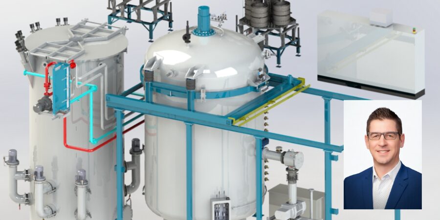
Producing durable, wear-resistant gears for the wind turbine industry requires exacting control of carbon diffusion. Modern low pressure carburizing (LPC) is pushing the boundaries of control and consistency. This technology fine tunes carbon diffusion into the surface of components, and applied in a new pit-style vacuum furnace, it also delivers temperature uniformity, stronger gears, and shorter cycle times for large, complex components, all while eliminating oxidation and direct CO₂ emissions. In this Technical Tuesday installment, Tom Hart, director of sales for North America at SECO/WARWICK Corporation, examines how modern LPC technology in a pit-style vacuum furnace is reshaping high-volume carburizing for today’s in-house heat treaters.
This informative piece was first released in Heat Treat Today’s November 2025 Annual Vacuum Heat Treating print edition.
The Need To Carburize
Carburizing is a thermochemical treatment that finds applications across the automotive, aviation, and energy industries, particularly in power transmission systems. The widespread use of this process across many industries stems from its ability to improve mechanical properties by enriching the surface of steel with carbon.
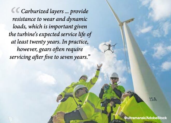
Consider the wind turbine industry, growing with a CAGR (compound annual growth rate) of 6.2% from 2024 to 2033 (GlobeNewswire 2024). Carburizing plays a key role in the production of gears and pinions. These components, often made of alloy steels, such as 18CrNiMo7-6, 4320, 4820, and 9310 (GearSolutions 2009, Jantara 2019), must meet high strength and quality requirements. Carburized layers, often over 4 mm thick, provide resistance to wear and dynamic loads, which is important given the turbine’s expected service life of at least twenty years.
In practice, however, gears often require servicing after five to seven years (Jantara 2019), with their failures generating long downtimes and high costs (Perumal and Rajamani 2014).
The carburizing process, combined with hardening (usually in oil) and tempering, increases:
- Surface hardness: improving abrasian resistance
- Core ductility: protecting against cracks
- Fatigue strength: extending the life of the part, which translates into lower operating costs
Alternative technologies, such as nitriding or surface hardening, offer other benefits (e.g., reduced deformation), but have limitations, such as thinner hardened layers, relatively long nitriding process times, or difficulties with complex geometry for surface hardening.
Pit Meets Vacuum LPC
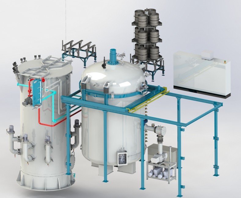
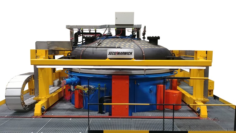
Traditional atmospheric carburizing, despite its established position, has reached its limits in process performance expectations. In response to market needs, LPC (low pressure carburizing) technology is being increasingly implemented to enable precise process control, reduced emissions, and improved energy efficiency. More specifically, a pit furnace with vacuum heat treatment capabilities, aka the Pit-LPC, has been designed and developed to carburize thick layers on very large and/or long parts. This furnace combines the advantages of LPC technology with the ability to integrate existing hardening cells, facilitating the modernization of older installations.
While a vacuum furnace opening to an air atmosphere is a feature previously reserved for atmospheric furnaces, this innovative pit furnace has ceramic insulation and a dedicated heating system to leverage this capability. The chamber door can therefore be opened at process temperature in an air atmosphere for the direct transfer of the charge to the hardening tank. Additionally, the furnace is equipped with a closed circuit forced cooling system, which significantly shortens the charge cooling time from the carburizing temperature to the hardening temperature, increasing efficiency and shortening the production cycle.
Furthermore, the furnace allows for the process to be carried out at temperatures of 1925°F (1050°C) and higher, significantly shortening carburizing time and reducing production costs, even while maintaining a safe level of grain growth (e.g., 1800°F (980°C)).
Benefits of LPC technology designed in a pit furnace include:
- Reduced process time due to higher operating temperatures
- Elimination of internal oxidation (IGO) in the carburizing process
- Highly uniform carburized layer
- Low process gas consumption
- No direct CO₂ emissions and fire risk
- Ready for operation without lengthy conditioning
- Computer-aided process support
Additionally, the furnace design increases work safety and comfort in its elimination of open flames, risks of explosion, and the need for constant atmospheric monitoring.
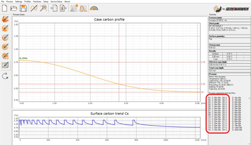
This new pit furnace is compatible with SimVac software, developed by Lodz University of Technology and SECO/WARWICK, which enables the simulation and optimization of LPC parameters, reducing the need for process tests. SimVac Plus is a simulation software that includes a vacuum carburizing module (Figure 2). The program can be used either as a standalone tool for designing processes based on the desired carburized layer requirements or to visualize the effect of a given boost/diffusion sequence in the form of a carbon profile.
Testing the Furnace Characteristics and Technical Parameters
The furnace was designed to meet the highest requirements for heat treatment equipment. The basic technical parameters are as follows:
- Working space / charge weight: 71″ diameter x 118″ deep / 17,600 lb (1,800 mm x 3,000mm deep / 8,000 kg)
- Operating temperature: up to 2010°F (1100°C)
- Heating power: 360 kW, three independent zones
- Vacuum level: 10⁻² torr
- Carburizing gas: acetylene
Temperature Uniformity
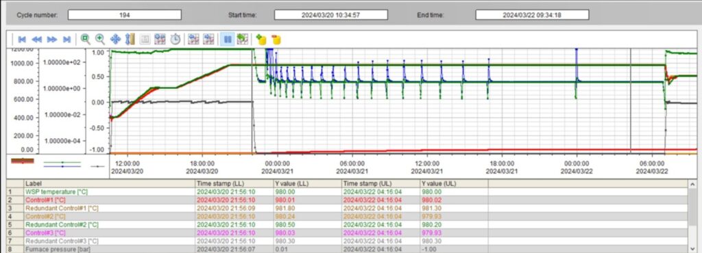
Temperature distribution tests were conducted in the furnace, with 12 load thermocouples arranged according to the diagram shown in Figure 2. Measurements were taken at several temperatures under vacuum conditions. The purpose of the tests was to confirm compliance with the Class 1 ±5°F (3°C) requirements of the AMS2750 standard.
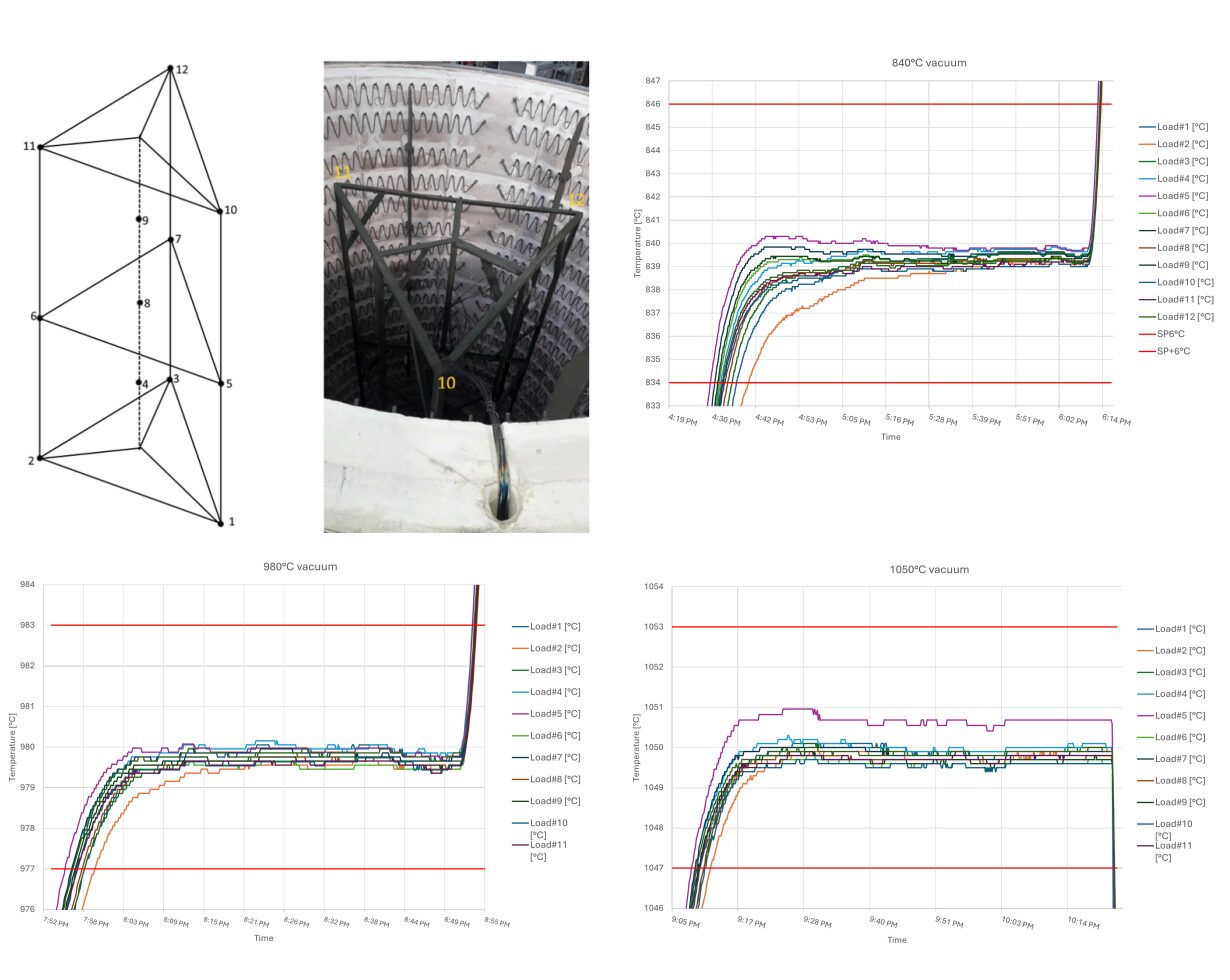
The results presented in Figure 3 indicate that the furnace provides above-average temperature uniformity, which is particularly important for a large workspace with 71″ diameter x 118″ deep (1,800 mm diameter × 3,000 mm deep) and the processing of large-sized components with thick layers. The temperature difference (ΔT) between the extreme thermocouples, measured at 1550°F (840°C), 1800 °F (980°C), and 1925°F (1050°C), did not exceed 3.5°F (2°C). This means that the furnace meets the Class 1 requirements of the AMS2750 standard by a wide margin.
Operational Dynamics
Additionally, to evaluate the furnace’s operational dynamics, heating and cooling tests were performed on an empty device with samples. Figure 4a shows the heating curve; the furnace reaches a temperature of 1800°F (980°C) in 60 minutes. The furnace’s high energy efficiency has a heat loss of just 32 kW under these circumstances.
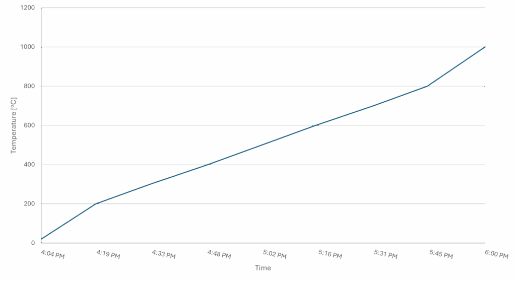
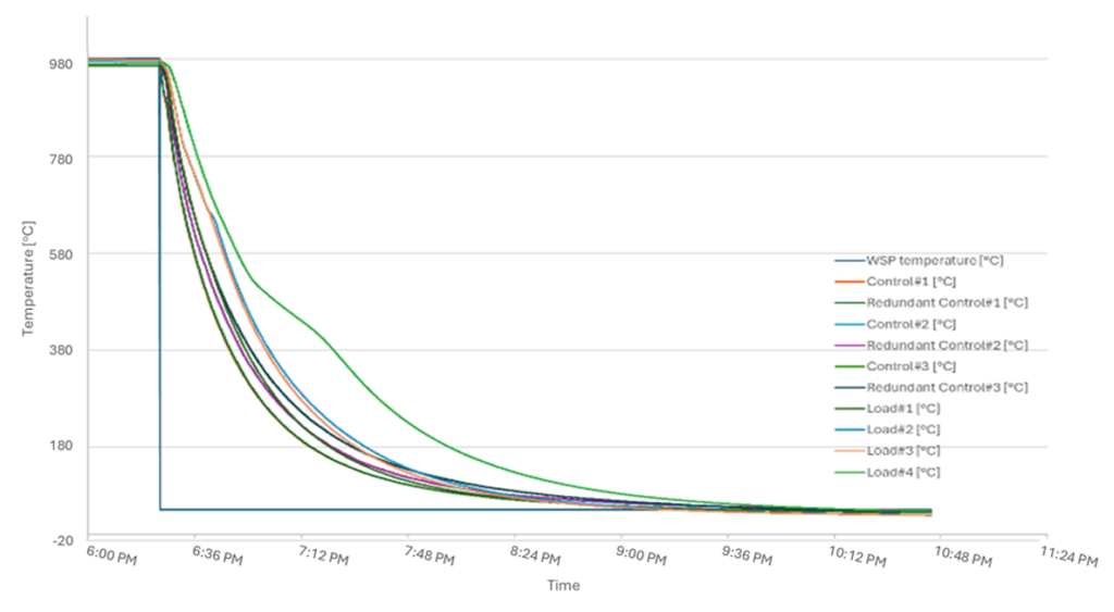
Figure 4b shows teh curve of cooling forced by nitrogen at atmospheric pressure, measured in three zones and on samples with diameters of 1″ (25 mm) and 4″ (100 mm). The temperature drops from 1800°F (980°C) to 575°F (300°C) in 60 minutes; reaching 210°F (100°C) takes only two hours, whereas natural cooling would take several days.
Vacuum tests show that the furnace reaches operating vacuum of 10⁻¹ hPa in under 30 minutes and has a leakage rate of 10⁻³ mbar·l/s, which meets the industry standard for vacuum furnaces.
Test of Atmosphere vs. Vacuum Carburizing Processes
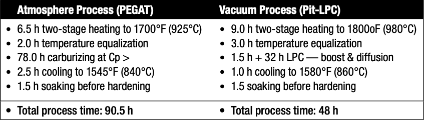
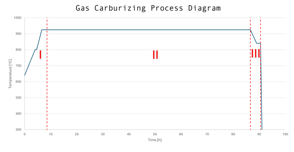
To obtain a carburized layer 0.145–0.160″ (3.7–4.0 mm) thick for 52.3 HRC (550HV1), two tests were compared: one in the PEGAT atmosphere furnace (Figure 5a) and another in the Pit-LPC vacuum furnace (Figure 5b). In both cases, the charge consisted of seven gears made of 18CrNiMo7-6 material, with a total weight of approximately 6.5 tons and a surface area of 280 ft² (26 m²). The process consisted of three stages:
- Stage I: heating to the carburizing temperature and soaking
- Stage II: actual carburizing with cooling to the hardening temperature and holding
- Stage III: hardening in an external quenching tank — identical in both processes
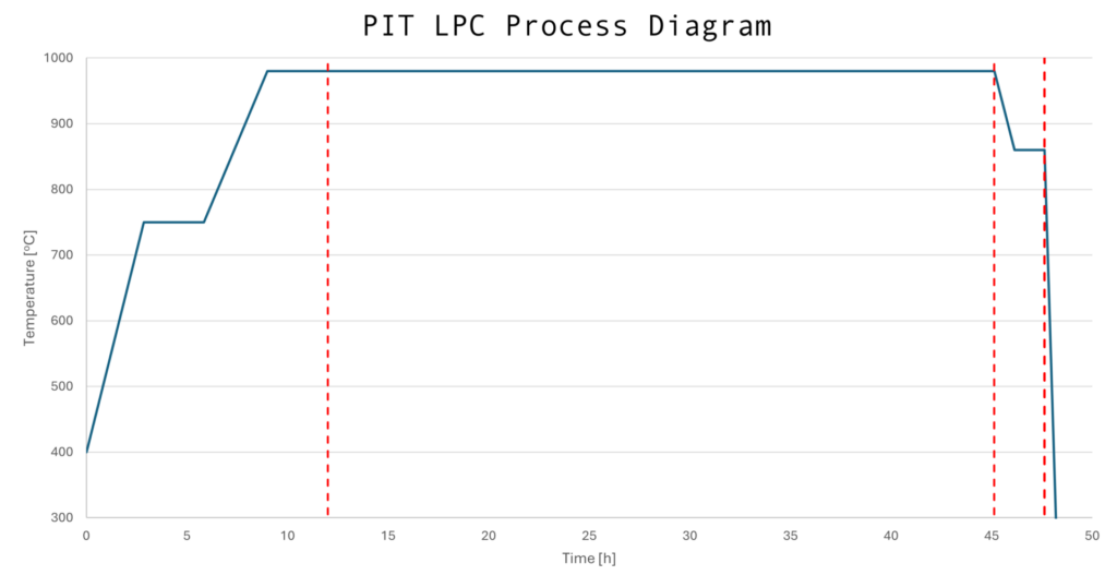
The LPC process, which consists of saturation and diffusion segments (Figure 6) allows for the precise control of carbon distribution. As the process progresses, the duration of the diffusion segments is extended, ensuring uniform saturation of the material.
After carburizing and hardening, all components were tempered at 355°F (180°C) for three hours.
Metallurgical Results: Gears & Samples Destructive Testing
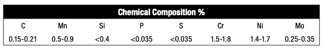
Gears and samples made of 18CrNiMo7-6 steel were used for destructive testing, in accordance with the EN 10084 standard. Six cylindrical samples were placed throughout the workspace — inside and outside the part — to assess carburization uniformity.
Tests conducted:
- Vickers microhardness (HV1): performed on a Struers Durascan 70 device, allowing for the determination of hardness profiles and carburized layer depth (ECD) — a load of 9.81 N (HV1).
- Surface and core hardness (Rockwell): measurements were performed on a Wilson Wolpert TESTOR tester with a load of 1470.1 N. At least five measurements were taken for each sample.
- Microstructure: assessed on a Nikon LV150 optical microscope after nital etching.
- Internal oxidation (IGO): analyzed on the unetched surface of the microsection.
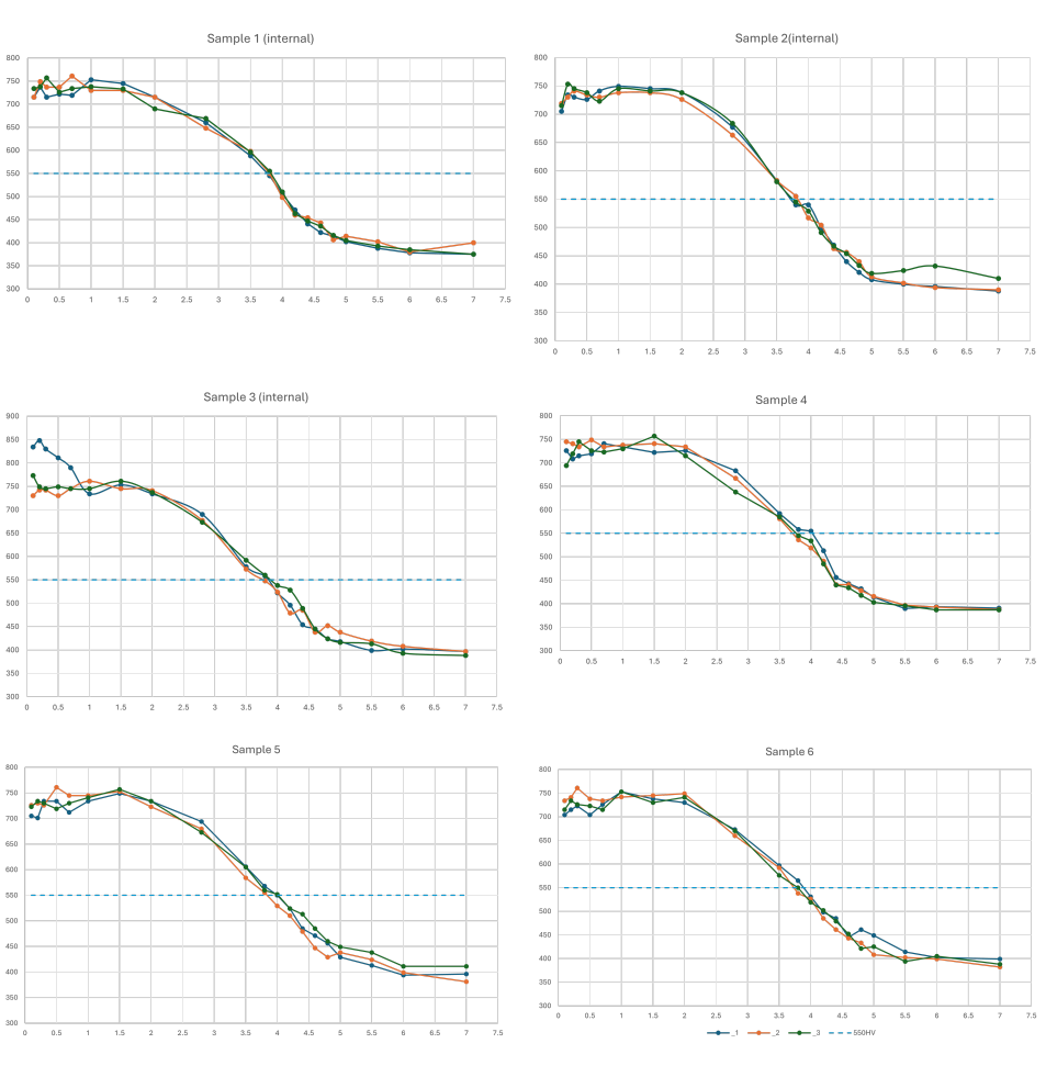
Figure 7 shows the microhardness profiles for the tested samples. For each sample, microhardness paths were inspected in three cross-sections. Based on this, the effective ECD layer thickness obtained on each sample was determined, as presented in Table C.
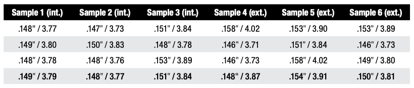
Average ECD values obtained for the samples ranged from 0.148 to 0.154″ (3.77 to 3.91 mm).
Surface and core hardness values for all samples were consistent and typical of carburized layers (Table D). Surface hardness ranged from 61.0 to 63.2 HRC and core hardness from 39.9 to 40.7 HRC. Interestingly, samples located on the inner side of the wheel achieved slightly higher surface hardness values (caused by retained austenite and cooling intensity).

Microstructure images of low-tempered martensite, along with retained austenite, were identified, ranging from 17 to 20% (Figure 8). The amount of retained austenite was determined using NIS-Elements software. No variation in structure was observed depending on sample location.
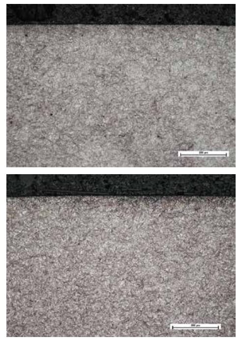
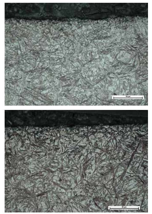
The presence of intergranular oxidation (IGO) was also inspected, averaging 5.5 μm throughout the tested samples. For comparison, intergranular oxidation in the atmospheric process averages above 15 μm. In the new LPC pit furnace, internal oxidation only occurs during unloading and transfer of the charge to the hardening tank, whereas in the atmospheric furnace, the presence of oxygen in the carburizing atmosphere is also significant, significantly increasing the IGO value.
The level of hardening deformation after the process conducted in the new LPC pit furnace and the atmosphere furnace is comparable due to the use of the same hardening tank in both devices and the absence of the carburizing process.
Comparison of Process Economics
Economic aspects play a key role in modern heat and thermochemical processing. Therefore, the consumption of basic utilities was compared for the reference processes (described in Chapter 5), resulting in a 0.152″ (3.8 mm) thick hardened layer. The analysis included a Pit-LPC and a PEGAT-type atmospheric furnace, both with identical workspace and the same charge. In addition, the LPC process was simulated at 1900°F (1040°C). The results are summarized in Table E.
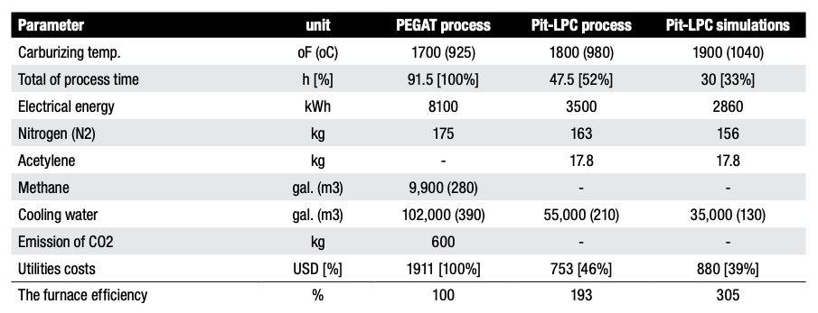
The results show that the new LPC furnace model consumes significantly less electricity by approximately 57%, which translates into a lower carbon footprint, especially when energy is derived from fossil fuels. Nitrogen consumption is comparable, with a slight advantage for the Pit-LPC (savings of up to 10%).
The largest differences are found in carburizing gases. The atmospheric furnace consumes 9,900 ft³ (280 m³) of methane — approximately 440 lb (200 kg) and an additional 4.4–13.2 lb (2–6 kg) of propane per process. In the LPC furnace, acetylene consumption is reduced to 39.2 lb (17.8 kg) because carburizing gas only flows during the boost phase.
Importantly, the LPC process does not generate direct CO₂ emissions, unlike an atmospheric furnace, which emits approximately 1325 lb (600 kg) of CO₂ per cycle. Cooling water consumption in the new LPC furnace is also reduced by over 45%.
The presented comparison of utility consumption in the two types of furnaces directly translates into the economic aspects of using these devices and conducting production processes. For cost comparison purposes, the following unit utility costs were assumed, as presented in Table F:
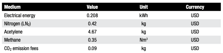
In summary, the total utility costs for the process conducted in the Pit-LPC at 1800°F (980°C) are 53% lower compared to an atmospheric furnace conducted at 1700°F (925°C). At a temperature of 1925°F (1040°C), savings reach 60%. These savings are primarily due to lower energy and process gas consumption. Furthermore, the lack of CO₂ emissions eliminates the need to pay emission fees.
The efficiency of this furnace is almost twice as much at 1795°F (980°C) and three times as much at 1925°F (1040°C) compared to an atmospheric furnace.
Summary
The new Pit-LPC vacuum furnace combines the design features of a top-loaded pit and performs carburizing using vacuum technology instead of atmospheric technology. Bringing higher processing temperatures than traditional atmospheric furnaces to the market, as well as the ability to open hot in an air atmosphere, this technology proves that direct transfer of the charge to the hardening tank is possible in vacuum furnaces.
Another key development, this design significantly shortens carburizing time compared to atmosphere furnaces since the furnace can operate under vacuum, inert gas (nitrogen, argon), air, and carburizing gases, at temperatures up to 2010°F (1100°C).
Since this new pit furnace design does not require the use a retort or atmosphere mixer, which are the most vulnerable components inside a traditional atmospheric furnace, the furnace operates with greater reliability and lower costs. Furthermore, an efficient and robust vacuum pumping system provides the vacuum environment and operational readiness in less than 30 minutes. Time is also saved by the integrated closed-loop gas cooling system that shortens cooling time: dropping temperatures from 1800°F (980°C) to 1545°F (840°C) in 30 minutes for a full charge and to 210°F (100°C) in two hours for an empty furnace, operations which would take several hours and days respectively in atmosphere furnaces.
The advanced thermal insulation and a uniform heating element layout ensure high energy efficiency and precise temperature uniformity in the working space, yielding additional cost and energy savings.
This carburizing process is based on FineCarb LPC technology and supported by the SimVac simulator, enabling precise carbon profile shaping and achieving layers 0.148–0.154″ (3.77–3.91 mm) thick with high repeatability.
With the ability to operate at temperatures up to 1925°F (1050°C), the new LPC pit-styled furnace significantly shortens process time, reduces utility consumption, and lowers operating costs by up to 50%, while increasing productivity by a factor of x2 to x3. One of these furnaces can replace two to three atmosphere furnaces of the same size.
Finally, the furnace operates in a safe and non-flammable atmosphere, emits no direct CO₂, and reduces energy consumption, making it an environmentally friendly solution.
Conclusions
The Pit-LPC furnace is a modern alternative to the traditional atmosphere furnace and offers a number of advantages in terms of quality, efficiency, safety, economy, and ecology. Providing an innovative solution for vacuum carburizing and meeting stringent carburization layer thickness guidelines, this design is a viable option to fully replace traditional atmospheric pit furnaces operating in a carburizing atmosphere.
References
GlobeNewswire. 2024. “Wind Turbine Market to Reach $115.2 Billion Globally by 2033 at 6.2% CAGR: Allied Market Research.” GlobeNewswire, September 18, 2024. https://www.globenewswire.com/news-release/2024/09/18/2948365/0/en/Wind-Turbine-Market-to-Reach-115-2-Billion-Globally-by-2033-at-6-2-CAGR-Allied-Market-Research.html
GearSolutions. 2009. “Carburizing Wind-Turbine Gears.” Gear Solutions, May 1, 2009. https://gearsolutions.com/features/carburizing-wind-turbine-gears/
Jantara, Valter Luiz Jr. 2019. “Wind Turbine Gearboxes: Failures, Surface Treatments and Condition Monitoring.” In Non-Destructive Testing and Condition Monitoring Techniques for Renewable Energy Industrial Assets, edited by Mayorkinos Papaelias, Fausto Pedro García Márquez, and Alexander Karyotakis. Amsterdam: Elsevier.
Perumal, S., and G. P. Rajamani. 2014. “Improving the Hardness of a Wind Turbine Gear Surface by Nitriding Process.” Applied Mechanics and Materials 591: 19–22.
Rolinski, Edward. 2016. “Modern Nitriding Techniques for Gear Applications.” Gear Solutions, March 16, 2016. https://gearsolutions.com/departments/hot-seat-modern-nitriding-techniques-for-gear-applications/
About The Author:
Director of Sales for North America
SECO/WARWICK Corporation
Tom Hart joined SECO/WARWICK in 2011 as a sales engineer and has been in the precision manufacturing industry for over 16 years. His responsibilities have him caring for SECO/WARWICK’s clients and their various process and heat treatment equipment needs. Tom received his manufacturing engineering degree from Edinboro University of Pennsylvania, has authored numerous white papers, and is recognized throughout the heat treatment industry as a go-to-guy for thermal processing.
For more information: Contact Tom at Tom.Hart@SecoWarwick.com.