El reporte de emisiones de carbono ya no es opcional para los especialistas en tratamiento térmico — se está convirtiendo en una necesidad competitiva y regulatoria. En esta entrega de Perspectivas de Sostenibilidad, Heat TreatToday examina la investigación del Profesor Fu Zhao y la candidata a Doctorado Lakshmi Srinivasan del Heat Treating Consortium de Purdue University, detallando una nueva calculadora de carbono basada en Python, desarrollada específicamente para operaciones de tratamiento térmico, cómo modela las emisiones del Alcance 1, 2 y 3 a partir de la geometría del horno y los parámetros del proceso, y cómo los especialistas en tratamiento térmico con operaciones internas pueden utilizarla para cumplir con las crecientes exigencias de transparencia con un mínimo de intervención manual.
Este artículo informativo se publicó por primera vez enHeat Treat Today’sFebruary 2026 Annual Air & Atmosphere Heat Treating print edition.
Si tiene comentarios o preguntas sobre este artículo, háganoslo saber en: editor@heattreattoday.com.
El reporte de emisiones se ha convertido en un paso esencial. Navegar los requisitos en un entorno político cambiante solo añade complejidad al desafío. ¿Cómo pueden los especialistas en Tratamiento Térmico mantenerse en el cumplimiento normativo? Una herramienta diseñada a través de Purdue University’s Heat Treating Consortium (PHTC, por sus siglas en inglés) podría ser la respuesta.
El consorcio ha financiado investigaciones en proyectos de tratamiento térmico que abarcan desde la eficacia de nuevos medios de temple hasta la mejora de dureza de los materiales. Hace aproximadamente dos años, las empresas miembros del PHTC solicitaron una investigación para el desarrollo de una herramienta que hiciera posible la estimación de carbono.
Lakshmi Srinivasan, Candidata a Doctorado en School of Mechanical Engineering at Purdue UniversityProfessor Fu Zhao, Miembro del Profesorado de School of Mechanical Engineering and the School of Sustainability Engineering and Environmental Engineering at Purdue University
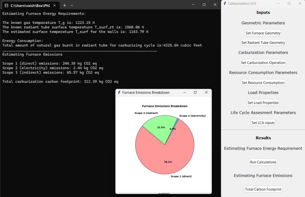
El Profesor Fu Zhao, miembro del profesorado de School of Mechanical Engineering and the School of Sustainability Engineering and Environmental Engineering at Purdue decidió asumir esta solicitud de investigación. Incorporando a la candidata a Doctorado Lakshmi Srinivasan, una destacada investigadora en el modelado de sistemas energéticos y evaluación del ciclo de vida en School of Mechanical Engineering y la School of Sustainability Engineering and Environmental, para la investigación y desarrollo de esta herramienta. “Este proyecto tiene como objetivo modelar los requerimientos energéticos del horno en función de su geometría y los parámetros de entrada de tratamiento térmico”, explicó Srinivasan. “A partir de estos flujos energéticos modelados y de los insumos asociados a la construcción del horno, calculamos las emisiones de carbono del Alcance 1, Alcance 2 y Alcance 3 asociados a la operación del horno”.
Alcance 1: Emisiones directas de carbono derivadas del consumo de energía dentro de la planta (por ejemplo, combustión de gas natural u otros combustibles)
Alcance 2: Emisiones indirectas provenientes de electricidad, vapor, calor o enfriamiento adquiridos
Alcance 3: Todas las demás emisiones indirectas a lo largo de la cadena de suministro (por ejemplo, proveedores, transporte, uso del producto)
La herramienta es una aplicación de escritorio basada en Python, diseñada pensando en la escalabilidad. Dado que el desarrollo está orientado al proceso de carburizado tanto por razones de mercado como regulatorias, se encuentra altamente enfocada en las necesidades de la industria. Adicionalmente, Zhao y Srinivasan diseñaron la herramienta para que los usuarios puedan integrar características adicionales y conjuntos de datos que se alineen con nuevos requerimientos o tecnologías emergentes. También subrayaron que la arquitectura de la herramienta está pensada para su crecimiento como una aplicación basada en la web.
Imagen de la herramienta digital de seguimiento de carburizado | Image Credit: Srinivasan and Zhao
La facilidad de uso es un aspecto esencial. Zhao y Srinivasan han refinado la herramienta para limitar la cantidad de entradas únicas requeridas por el usuario para generar un resultado preciso. El equipo explicó que este aspecto fue particularmente desafiante, ya que se examinaron alternativas para simplificar la interfaz sin simplificar en exceso la “física subyacente”. Describieron como funcionará la versión final de la herramienta, explicando que una vez que se introduzcan los parámetros clave (tipo de horno, temperaturas de proceso, tiempo, pieza) la herramienta automáticamente calculará la energía usada y las emisiones con una intervención manual mínima.
Los miembros del PHTC, de los cuales muchos representan compañías manufactureras que cuentan con tratamiento térmico interno, han mostrado interés, proporcionando retroalimentación y recursos para dar forma al desarrollo de la herramienta. Un entusiasmo adicional se observó durante el IHEA’s annual SUMMIT en agosto de 2025, donde Srinivasan presentó el desarrollo de la herramienta. Cuando se les preguntó qué interrogantes han guiado su investigación, Zhao y Srinivasan compartieron lo siguiente:
Versatilidad y funcionalidad: ¿Qué tan flexible es la herramienta para adaptarse a diferentes geometrías de horno, geometrías de piezas, tipos de hornos y procesos de tratamiento térmico?
Asignación basada en piezas: ¿Cómo asigna la herramienta las emisiones de manera precisa a piezas individuales o lotes de una carga dentro del horno?
Emisiones específicas por ubicación: ¿Cómo considera las variaciones regionales en las emisiones del Alcance 2 y Alcance 3, tales como las diferencias en la generación de electricidad o los impactos de la cadena de suministro?
Otro desafío ha sido garantizar la calibración y verificación cuidadosa de la herramienta. Para ello el equipo ha utilizado datos reales y precisos de consumo de gas natural y electricidad provenientes de operaciones de tratamiento térmico, cortesía de los miembros del PHTC, con el fin de verificar el consumo energético predicho por el modelo a temperaturas de operación definidas del horno.
Eventualmente alguna versión de esta herramienta estará disponible para usuarios fuera del consorcio. Sin embargo, actualmente, los miembros del PHTC se encuentran a la vanguardia tanto del desarrollo como del uso. Los investigadores enfatizaron este punto: “Esta herramienta es particularmente oportuna y esencial para la industria, ya que las empresas enfrentan una creciente expectativa de proporcionar reportes de emisiones transparentes y precisos”.
Si bien el mundo de las normas y regulaciones puede sentirse como un campo minado, las discusiones comparativas sobre esta herramienta revelan aplicaciones prometedoras a corto plazo para los especialistas en tratamiento térmico con operaciones internas.
Carbon emissions reporting is no longer optional for heat treaters — it’s becoming a competitive and regulatory necessity. In this Sustainability Insights installment, Heat TreatToday examines research from Professor Fu Zhao and PhD candidate Lakshmi Srinivasan of Purdue University’s Heat Treating Consortium, detailing a new python-based carbon calculator built specifically for heat treat operations, how it models Scope 1, 2, and 3 emissions from furnace geometry and process parameters, and how in-house heat treaters can use it to meet growing transparency demands with minimal manual effort.
This informative piece was first released in Heat Treat Today’sFebruary 2026 Annual Air & Atmosphere Heat Treating print edition.
Emissions reporting has become an essential step. Navigating the requirements in an influx political environment only adds to the challenge. How can heat treaters remain in compliance? A tool designed through Purdue University’s Heat Treating Consortium (PHTC) may be the answer.
The consortium has funded research across heat treat projects ranging from the efficacy of novel quenchants to improving materials hardness. Roughly two years ago, the PHTC member companies requested research to develop a tool that would make carbon estimation possible.
Lakshmi Srinivasan, PhD Candidate in the School of Mechanical Engineering at Purdue UniversityProfessor Fu Zhao, Faculty Member at the School of Mechanical Engineering and the School of Sustainability Engineering and Environmental Engineering at Purdue University
Professor Fu Zhao, faculty member at the School of Mechanical Engineering and the School of Sustainability Engineering and Environmental Engineering at Purdue, decided to take on this research request. He brought on PhD candidate Lakshmi Srinivasan, an astute researcher of energy systems modeling and life cycle assessment in the School of Mechanical Engineering, to research and develop the tool. “This project aims to model furnace energy requirements based on furnace geometry and heat treating input parameters,” Srinivasan explained. “From these modeling energy flows and furnace build inputs, we calculate Scope 1, Scope 2 and Scope 3 carbon emission associated with operating the furnace.”
Scope 1: Direct carbon emissions from energy consumption within the plan (e.g. combustion of natural gas or other fuels)
Scope 2: Indirect emissions from purchased electricity, steam, heat, or cooling
Scope 3: All other indirect emissions across the supply chain (e.g., suppliers, transportation, product use)
The tool is a python-based desktop application with scalability in mind. Since development targets the carburizing process for both market and regulatory reasons, it is highly focused on industry needs. Additionally, Zhao and Srinivasan built the tool for users to integrate additional features and data sets to align with new requirements or emerging technologies. They also underscored that the tool’s architecture is designed for growth as a web-based application.
Image of the digital carburization tracking tool | Image Credit: Srinivasan and Zhao
Ease of use is central. Zhao and Srinivasan have refined the tool to limit how much unique user input is required to generate an accurate output. The team explained this as particularly challenging, having examined alternatives to simplify the interface without oversimplify the “underlying physics.” They described how the final form of the tool will work, saying that once key parameters are entered (furnace type, processing temperatures, time, part geometry), the tool will automatically calculate energy usage and emissions with minimal manual intervention.
PHTC members, many of whom represent manufacturers with in-house heat treating, have shown great interest, providing feedback and resources to shape the development of the tool. Additional enthusiasm was found at IHEA’s annual SUMMIT in August 2025, where Srinivasan presented the tool’s development. When asked what inquiries have directed their research, Zhao and Srinivasan shared the following:
Versatility and functionality: How flexible is the tool in accommodating different furnace geometries, part geometries, furnace types, and heat treatment processes?
Part-based allocation: How does the tool allocate emissions accurately to individual parts or batches within a furnace load?
Location-specific emissions: How does it account for location-based variations in scope 2 and scope 3 emissions, such as differences in electricity generation or supply chain impacts?
Another challenge has been ensuring careful tool calibration and verification. To do so, the team has taken accurate, real-world natural gas and electricity consumption from heat treat operations, courtesy of PHTC members, to verify the model’s predicted energy consumption at defined furnace operating temperatures.
Eventually, some form of this tool will be made available to those outside the consortium. Currently, however, PHTC members are at the forefront of development and usage. The researchers underlined this, commenting, “This tool is particularly timely and essential for industry, as companies are increasingly expected to provide transparent and accurate emissions reporting.”
While the world of standards and regulations can feel like a minefield, benchmarked discussions of this tool reveal promising applications for in-house heat treaters in the near future.
AI is moving from concept to practice in heat treating — driving furnace optimization, smarter scheduling, and predictive compliance. In this Q&A, Peter Sherwin, strategic marketing at Watlow, highlights how Model Context Protocol (MCP) will connect data, tools, and operators to reshape the industry’s digital future.
This informative piece was first released inHeat Treat Today’sOctober 2025 Ferrous & Nonferrous Heat Treatments/Mill Processing print edition.
Q1. What do we mean by “AI” in industrial heat treat?
It is probably best to start with a contrast. We have fixed code in heat treat applications, such as a setpoint programmer that is pre-programmed with ramps and soaks at specific temperatures for specific times. I like to think of AI (artificial intelligence) as introducing the concept of flexible code that learns from data over time.
AI has been used for a surprisingly long time in heat treatment. The original autotune algorithms used a form of AI and machine learning to adapt the PID parameters to a specific furnace, learning from real equipment process signals (such as temperature sensors) to provide optimum control.
Q2. Where is AI already working in heat treat?
AI is most obviously used in equipment optimization, and there are a growing number of cases expanding from process control to energy optimization. Less obvious uses are within the heat treating plants. For example, AI in contract review can highlight key customer requirements, pull together relevant specifications, and help craft recipe design or selection.
A common issue across plants is the need to continually optimize and re-optimize production planning and scheduling. Because heat treating occurs near the end of the manufacturing chain, last-minute changes are common. The ability to quickly re-plan based on specific requirements is a typical use of AI.
Following the process, quality analysis is now supported by AI with optical microscopy that leverages microstructural datasets. AI can also be used for financial analysis, recruitment, and customer support.
Q3. What is MCP?
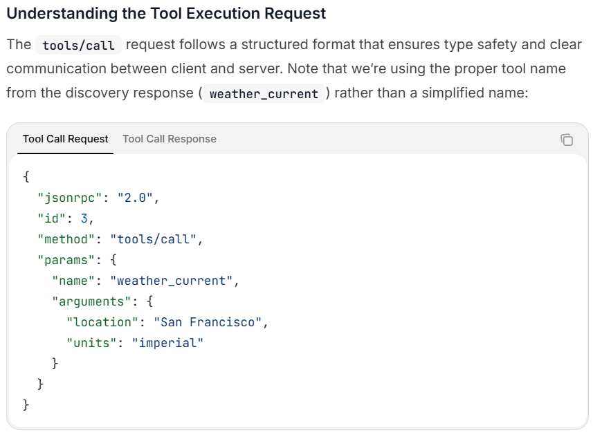
Model Context Protocol (MCP) is a structured method for AI applications and agents to securely discover data, call tools, and share context. Developed by the engineering team at Anthropic in 2024, it has now received widespread adoption across major technology providers, such as Microsoft and OpenAI.
In simple terms, it enables large language models (LLMs) to communicate reliably with other data sources.
Q4. What MCP adoption is happening today?
It is still early, but MCP adoption is accelerating rapidly. Most software companies are developing MCP servers. Many B2C applications already exist, and there are now a growing number of industrial applications, such as those from Highbyte, Flow Software, and Siemens.
Q5. What will “MCP-compliant” mean for AI developers?
From a developer’s perspective, this should be easier than crafting individual application programming interfaces (APIs) that require strict mapping between software products. Any changes on the other end of the system would normally require the API to be restructured. MCP is expected to support inheriting updates without code changes and provide a more uniform setup.
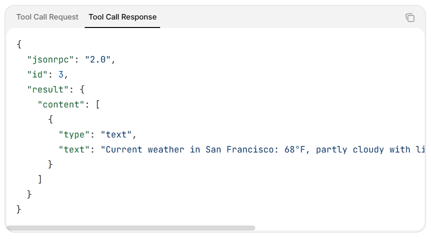
Figure 1a. MCP Standard screen capture of how to use the tool. (Screen capture from the “Architecture overview” page of modelcontextprotocol.io.)Figure 1b. Toggle to the “Tool Call Response” to view the response for that example input request. (Screen capture from the “Architecture overview” page of modelcontextprotocol.io.)
Q6. How would MCP specifically benefit heat treat?
In the last 30 years, I have seen three waves of technology. The first wave was automation that leveraged PLCs, setpoint programmers, and carbon probes to reduce manual errors and improve utilization.
The second wave focused on regulations in aerospace (AMS2750) and automotive (CQI-9) to harmonize auditing processes, improve quality, and reduce in-use failures (reducing recalls). These regulations focused on ensuring ongoing equipment capability (such as TUS for furnaces and ovens), instrumentation and quality thermocouples via SATs, independent calibration, and operator procedures and training.
The last wave focused on Industry 4.0 and IIoT to further automate and optimize previous improvements. However, apart from some isolated cases, many Industry 4.0 solutions have not delivered the expected value. There are many potential reasons, but one standout is the focus on continued machine automation at the expense of human intervention.
The benefit of MCP is that it acts as a bridge between data and the people who need to use that data to improve processes.
Q7. What are the biggest adoption barriers (and how to reduce them)?
I am typically an early adopter of technology. I was asked to automate a manual sealed quench furnace (batch integral quench) to automatic setpoint and carbon control in the early 1990s, which was one of my first projects. I began exploring technology solutions for Industry 4.0 and IIoT back in 2013. There will always be both early adopters and laggards.
Sometimes it makes sense to wait until technology matures and becomes more reliable, but this feels different. For the first time, data will build upon data, and learning early from that data will put companies ahead.
Cybersecurity and IT policies will scrutinize any new technology. One opportunity for AI is to also strengthen cybersecurity robustness. I recently heard that if you do not respond to a technology breach within 30 minutes, you will lose significant data. Human intervention alone will not be fast enough. AI is truly a double-edged sword.
There is also a growing fear that AI will take jobs. This has been demonstrated in the software industry, where it is estimated that 30 percent of code is now written by AI. I do not believe a heat treater can reduce staff further, since most are already operating with skeleton crews. The real opportunity is to enable all individuals to accomplish more, supported by AI.
The final point is when to adopt this technology. The pace of improvement over the past two years has been tremendous, and we are only now reaching the point where new models are robust enough for industrial application.
Q8. Pace of change: start now or wait?
The base LLMs needed time to improve and become more reliable while reducing hallucinations. Each version of ChatGPT has made significant leaps in knowledge and robustness. The latest model, GPT-5, is beginning to provide the level of reliability needed for industrial applications; this progress will continue.
Q9. What AI-powered products or services will emerge with MCP?
We can do a bit of future gazing. I compiled several ideas as part of my preparation for my presentation at ASM Heat Treat in October. In each example below, you will notice that a human remains in the loop. Instead of manually fetching specific data and information, the agent provides timely information.
EnergyOptimizerAgent — Subscribes to “Power/Furnace*/kW” tags and day-ahead tariff feeds. Models alternate start times and sends a proposal called “propose_shift” to a PlanningAgent. If planners accept, the new schedule is written back to the UNS so control logic and enterprise resource planning (ERP) software stay aligned.
ComplianceAgent — Monitors SAT and TUS counters published by the Edge Process Management (EPM) platform. When drift approaches a set threshold, it issues “propose_sat” with a suggested window and part list. After the test, AuditPackAgent gathers .uhh files and publishes a cryptographic hash so auditors can verify authenticity without manual file transfers.
UniformityMonitorAgent — Streams zone temperatures and compares each batch with stored “golden” fingerprints. If deviation grows, it assembles options, such as rerouting the load or adding a soak. Operators approve or reject through a dashboard.
MaintenanceSchedulerAgent — Reads valve-cycle counts, fan-vibration spectra, and motor current signatures. Calls a computerized maintenance management system (CMMS) tool to open a work order, reserve a slot, and order spare parts when limits are reached.
OperatorCopilotAgent — Listens to every proposal on the MCP bus and presents it in chat form. For example: “Shift Load B932 to 13:30 to avoid the peak tariff. Accept or ask why.” One tap reveals historian trends, specification clauses, and the agent’s reasoning trail, giving junior staff instant context while keeping humans in charge.
Q10. Any drawbacks or cautions with MCP?
AI and MCP will continue to be targets for cybercrime. It is important to architect any solution so that the base control and operation of equipment remain safe, even if the AI layer is breached.
At ASM Heat Treat, I will touch on some architectural solutions that can support safer AI implementations. As with anything internet-related, precautions must be taken. With AI, you also introduce the possibility of human-like imposters.
There is risk in everything we do, and everyone needs to continually assess risk versus reward. In many cases, MCP may tip the balance by providing more value than past technology solutions.
The responses in this article represent Peter Sherwin’s personal views and not necessarily those of his organization.
About The Author:
Peter Sherwin Strategic Marketing Watlow
Peter Sherwin is passionate about offering best-in-class solutions to the heat treatment industry. He is a chartered engineer and a recognized expert in heat treatment control and data solutions.
In this episode of Heat TreatRadio, Tony Busch of Control Concepts, Christina Clowes of I Squared R, and Dr. Stephen Feldbauer of Abbott Furnace Company join host Doug Glenn to discuss a new transformer-free approach to electrically heated furnaces. The group walks through how SCR power controllers paired directly with silicon carbide heating elements can reduce system cost, simplify design, and improve control accuracy. They also explore the global adoption of zero-cross technology and its growing relevance in North America.
Below, you can watch the video, listen to the podcast by clicking on the audio play button, or read an edited transcript.
The following transcript has been edited for your reading enjoyment.
Introduction (0:45)
Doug Glenn: We’re going to be talking about a relatively new combination of two fairly well-known technologies that will help some people save money. Those two technologies are SCR power controllers and silicon carbide heating elements. It’s actually kind of a little case study. If you’ve got an electrically heated furnace, this would be one you’ll want to stay and hear.
Clockwise from top left: Doug Glenn (host), Christina Clowes of I²R Elements Company, Tony Busch of Control Concepts, and Dr. Stephen Feldbauer of Abbott Furnace Company
Our first guest is Tony Busch from Control Concepts. Tony Busch is the North American sales manager for Control Concepts. Next is Christina Clowes, the vice president over at I²R Elements Company. Our final guest is Dr. Stephen Feldbauer, the director of research and development at Abbott Furnace Company.
A Furnace with a New Configuration (1:45)
Doug Glenn: To get a sense of this furnace that we’re talking about, can you describe the situation and this new configuration of power controls for the heating elements?
Steve Feldbauer: What I can say is that this was a new piece of equipment to replace an old technology for a new facility.
Okay, so they were going to move to a new facility and they said, “Hey, we don’t want this old stuff. Let’s look at just buying a new furnace for this application.”
This is for the casting industry. The molds go into the furnace and traverse through; the furnace preheats them so that operators can then pull them out and fill them with metal. So it’s a continuous furnace for mold preheating application for the casting industry.
It was exciting! We had an electrically heated furnace, and then began talking with Tony and Christina. Control Concepts had this concept, no pun intended: Traditionally, design of an electrically heated furnace above a certain temperature (1850 degrees), we use silicon carbide heating elements and — due to resistance changes over time — we have to put transformers in there that allow us to keep upping the voltage and maintain heating capability. Control Concepts said, “Hey, we can take innovate technology and save some money, make things a little easier, and get rid of the transformers.”
And we really had a great outcome.
Doug Glenn: This is a foundry industry application, the preheating of molds, and this is a continuous furnace. You guys, Abbott, obviously won that bid to supply that furnace. I’m sure it was a competitive situation, so congratulations.
TraditionalSCR and Silicon Carbide Heating Element Configuration (4:40)
Doug Glenn: So Tony, one of the great features of this Abbott furnace that helped them win this order was this relatively new configuration of the power supplies. as Steve was saying. Tell us a little bit more about the SCRs and the silicon carbide heating elements.
Tony Busch: I think it’s important to understand where we came from and where we are now with this new technology.
In the past, at least in North America, silicon carbide heating elements produce a high temperature, a high current. To help that happen and so you do not have a big, thick gauge wires, a transformer would be added to the design very close to the furnace. This reduces the conductor size. That transformer often was a multi-tap transformer. From a SCR power controller standpoint, you would be controlling the power on the primary side of the transformer, let’s say 480 volt stepping down into 60-70, whatever volts are required for the application. To use a transformer with a power controller, you need phase angle power control.
This is how it has been done in the past with phase angle firing varying every half cycle into the primary of a transformer.
The New Setup (06:09)
Example of SCR power controller units attached directly to industrial furnace. Source: Control Concepts
Doug Glenn: What is the new configuration?
Tony Busch: With the new scheme, we are removing the transformer. Now you have an SCR power controller firing directly into the silicon carbide heating elements.
To do this, you will have to have slightly bigger power controllers, but you’re completely eliminating the transformer and you’re going directly into it. To take it a step further, we use a special firing mode called Fast Zero Cross. This mode satisfies the heating elements.
We are maintaining a very smooth watt density output to the heating elements. You can control it and the power feedback if you need to, which is essentially your unit of measure to control the power, which can be in KW versus voltage or current.
Doug Glenn: That’s on the power side. Control side of things. That’s basically the new arrangement: removal of the transformer; direct feed into the heating element, with some advantages. Christina, how about the heating element? Can you tell us a little bit about the heating element in this situation?
Christina Clowes: This is not a unique heating element in this particular case, because the same heating element configuration probably would’ve been used even if you were using a multi-tap transformer based system.
The key to the operation here is the very rapid switching of full sine waves through the heating elements, where you’re proportioning the “on-to-off” cycles, electrical cycles, so rapidly that the heating element does not have time to respond to the very high instantaneous loadings during each “on” cycle.
For example, in the U.S., typically you are looking at a power supply that’s at 60 hertz, 60 cycles per second. One electrical cycle is one 60th per second, or 16.66 milliseconds. In that case, if you were regulating the outputs from the heating elements to 50%, you would have one cycle on, followed by one cycle off, and that being repeated continually.
The heating element during that one cycle, that 16.66 milliseconds, does not have enough time to respond firmly to that very high loading. As a result, the RMS voltage, the natural average voltage over time, governs the load into the heating elements. So, you can design around systems based on 480 volts but regulate the RMS output on the controller to whatever the heating element needs to generate the amount of power that’s needed by the process.
The control is the key to this operation.
Doug Glenn: Is it possible to use a standard or any type of heating element or do you need a special silicon carbide type?
Christina Clowes: It is not a special silicon carbide. We designed this particular application around the needs of the process, the operating temperature, the specific loading required for the process. But it is a different control methodology that’s really the key.
New Technology for North American (10:22)
Doug Glenn: While this technology is somewhat new in North America, it is actually not new on a global context. Can you address this?
Christina Clowes: In Europe, this kind of zero-cross base system has been commonplace for quite some years; also in Asia. The difference in North America is, I think, tradition, more than anything else. People have been used to using phase angle control for silicon carbide heating elements. That’s kind of where this technology grew out from, and people have stuck with that because it works. But this new technology though gives an opportunity to save money and space, while achieving the same result.
Doug Glenn: So for the North American market, this is somewhat new. But it is a proven technology. It’s not a new technology that we are still trying to get our hands around. It’s been done globally, which is an important point.
Cost Savings for the Customer (11:45)
Doug Glenn: With respect to cost savings for the customer, can you describe the capital expenditures, operating costs, and even maintenance costs?
Steve Feldbauer: We know that by eliminating the transformer, there’s the substantial costings. The SCR is doing the change in the voltage and controlling and eliminating that need for the transformer.
By eliminating that piece of equipment, you’re seeing upwards of anywhere between a 50 to 75% cost savings per heating zone. That’s a big number. There’s a wide range in that cost savings depending on the size of the heating zone, the size of the furnace, and the number of heating zones. That is a substantial saving.
In addition, the customer sees savings in shipping costs. In this case, removing the transformer reduced the size of the furnace by 2,100 pounds. That goes directly into your shipping cost.
Customers also see a lot less downtime because every time that you would want to change the tap in a traditional furnace, you have to power the furnace down, which interrupts production. There’s a knowledge base needed to know when and how to change the tap. But with this new technology, the furnace just continually operates.
There is also space savings. That transformer takes up space, which limits where we can put in things. For example, for the last line on a continuous furnace with a belt, the placement of the belt is dictated by where we put the transformers because the transformers typically go up underneath the hot box. Without the transformer, we now have flexibility and design.
So, we save in a number of different areas.
Maintenance of the SCR (14:24)
Doug Glenn: Maintenance wise, are the SCRs easier to maintain?
Steve Feldbauer: There is not much maintenance required for the SCRs. Once you put them in and they are set up, our customers really do not have to touch them unless they have to replace them. As far as tuning them and similar maintenance, there’s really not a lot that goes into them. Especially since now, you’re also not changing voltages. There’s not a lot of variability in the system. It’s set up and it just sits there and controls itself.
Advantages for the Customer (17:45)
Doug Glenn: What are the advantages for the customer?
Steve Feldbauer: There are many advantages in terms of cost, maintenance, and the ease in usage. There’s also less training, because you’re not teaching someone when or how to change a tap. This is a marked change in how you look at electrical furnace control in North America. This is something that is widely used throughout the rest of the world, so it’s not a new technology, but it’s new and innovative to North America. If you can optimize and streamline the process, why wouldn’t you?
Upgraded Features: Digitization and Data (18:58)
Doug Glenn: I also understand there are upgraded features because you’ve moved to an SCR and into a digital world with being able to get data back out of the furnace and understand the operation of the system because of the digitalization of it. Do you want to address that?
Tony Busch: By having a digital SCR power controller, you can connect up to your network, whether it’s Ethernet IP or Modbus TCP. You are able to collect all of that data. From that data, you are able to do things such as monitor the KW per hour. If you’re starting your process, and you want to know how much power was consumed during that particular time period, you can reset your KW per hour. Then you can find out how much you consumed when you are done and evaluate your efficiencies. All of that is recorded within the power controller. It’s essentially an industrial grade power meter built in.
Also, now that you are directly coupled with the silicon carbide heating elements, you have a very accurate load resistance monitoring capability. You are able to analyze the resistance and determine the health of your silicon carbide heating elements.
You can also plot a resistance curve. So you would know that if tolerance drifts 10, 20, 30%, you may be looking at a predictive maintenance situation where you look at your heating elements at some point and monitor the load currents. For a three-phase setup, if you notice that one of the phases is unbalanced, you may want to evaluate and determine the cause. You are able to be alerted without manually getting in there with a multimeter and doing your own research.
Christina Clowes: Compared to phase angle firing, which has been historically the most commonly used in North America, switching to a zero-cross system, a full sine wave based system, the SCRs turn on and off at zero volts potential.
To learn more about how SCR power controllers support tighter control when directly coupled with heating elements, you can click the image above to read this in-depth technical article co-written by Tony Busch.
As a result, that doesn’t produce any transient spikes that create a harmonic overlay, so there’s no electrical noise being generated. Utility companies do penalize their customers for generating electrical noise on their supplies.
In addition, because you have false sine waves, you have unity power factor, essentially. There’s no poor apparent power factor, which you have with a phase angle firing because you’re chopping the sine wave and conducting only part of the sine wave.
When you have purely resistive load, in the case of a Star Bar element, there’s no reactance, inductance, or capacitance. But because of the way that a phase angle SCR fires, it appears that there’s a power factor and people pay for energy that they are not consuming. This is more efficient way of driving an element system with a better handle over the energy that you’re consuming.
Doug Glenn: Is it more difficult to engineer these systems?
Christina Clowes: The exciting or interesting part is introducing new technology to people that actually helps them and provides real benefits. The total cost of the system is simplified and reduced, which makes it far more attractive for Star Bar-based systems to be sold into applications.
Doug Glenn: Right, right. Okay. Tony, how about you? What was interesting and challenging?
Tony Busch: Sure, yes. Christina touched on it a little bit. It would be that power factor in harmonics — being able to show the ability and not be penalized from your utilities for power factor and potential harmonics. Those questions come up, you know, pretty much anytime you’re using an electric furnace and SCR power controllers, but it’s much more easy to demonstrate to customers that you’re not going to see any of those issues. And I’ve seen our electric bill. When you’re running phase angle, you get these big old penalties that come up on there. It’s nice to be to pass that savings onto the customers with this new application.
Doug Glenn: Yeah. Yeah, that’s interesting. And Steve, I saved you for last because you were the ones that really had to interface with the customer. What was interesting or challenging for you guys?
Steve Feldbauer: I’ll tell you what, it was exciting for us to be able to provide new technology — new to North America — that number one makes it simpler for the customer to use.
You know, one of the challenges is always trying to teach people, “when do I need to change a tap or is there really some other problem?” Well, this eliminates that. Now we’re helping them to be able to operate the furnace more efficiently. And, you know, they don’t require all of the training.
We’re also able to pass on some cost savings because we aren’t buying that transformer. We’re able to have some leeway internally for design and construction. So all the way around, it’s a win-win, right? For the customer, for us, and for the industry, in general. Because now we’re able to move the heating technology forward.
Sustainability Benefits of the SCR Power Controller (26:31)
Doug Glenn: Yeah. I probably should have asked this question before, but there’s always a lot of talk about sustainability and greenness. Are there advantages here on this system?
Steve Feldbauer: Tony, you want to talk about it? I’m sure you can address the harmonics and different things that actually help out.
Tony Busch: Most definitely. From a power controller standpoint, the efficiency is right around 99.9%; you’re not really getting any losses through the power controller. And now you’re talking about being full wave firing, so you’re not trimming back that sine wave, you’re eliminating all those other harmonics. You should see a benefit from all of your equipment, if they ever experience that as well as, and your utility bill, not seeing that power factor.
Doug Glenn: Yeah. So basically I guess that’s it. The simple answer is if you’re reducing your energy bill, then obviously we’re using less energy and that’s probably less of a carbon footprint depending on where your electricity’s coming from. Well guys, thanks very much. This is a very interesting, great partnership between the three companies, obviously for the benefit of customers. Appreciate you working for the benefit of a customer and for spending a little bit of time with us here today.
About the Guests
Tony Busch North American Sales Manager Control Concept
Tony Busch is Control Concept’s North American Sales Manager. Currently in his 15th year with Control Concepts, he has experience in assembly, testing, troubleshooting, field service and an expert understanding of application engineering of SCR power controllers. Tony has a bachelor’s degree in electrical construction from Dunwoody College of Technology which he now applies the electrical concepts to power controllers and their related applications.
Christina Clowes Corporate Vice President and Director I Squared R Elements Co., Inc.
Christina Clowes is the Corporate Vice President and a Director of I Squared R Elements Co., Inc., located in Akron, NY. She has been at I Squared R for the past 9 years and a little over 40 years in the thermal processing industry, focusing on new product and application development.
Dr. Stephen Feldbauer Director of Research and Development Abbott Furnace Company
Dr. Stephen Feldbauer received his Ph.D. in 1995 from Carnegie Mellon University in Materials Science and Engineering. He joined Abbott Furnace Company in 2002 where he is currently the Director of Research and Development. Dr. Feldbauer is also a Senior Adjunct Faculty member in Engineering at the Pennsylvania State University. He is the author of numerous articles, publications, and has been awarded eight patents in both the USA and Europe. He is an active member of the MPIF, the American Welding Society’s C3 Committee on Brazing, and a co-chair of the Markets committee of NAATBatt International.
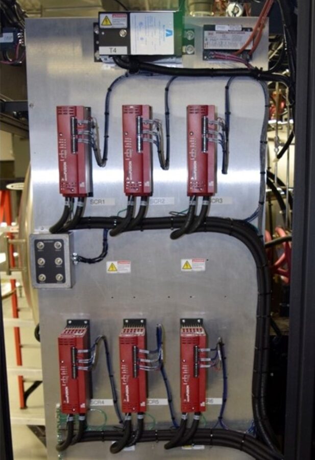
There are many avenues for achieving new feats in sustainability. One foundational method of pursuing sustainability is efficient furnace design. In this Control’s Corner installment of Technical Tuesday, Stanley Rutkowski III, senior applications engineer, RoMan Manufacturing, Inc., explores ways to design furnace electrical power systems for efficiency.
This informative piece was first released inHeat Treat Today’sJune 2025 Buyers Guide print edition.
In the world of industrial heat treating, sustainability isn’t just a buzzword; it’s a measurable outcome of engineering decisions. While discussions around energy usage often focus on renewable sources or carbon offsets, the path to sustainability begins much earlier — with the design of the furnace’s electrical power system.
From transformers and load configurations to modern control technologies, every part of the furnace power pathway affects how efficiently energy is used — and how much of it is wasted. A well-designed system doesn’t just heat effectively; it does so with less resistance, fewer losses, and minimal disruption to the power grid.
The Power Triangle: Real, Reactive, and Apparent
Understanding sustainability starts with understanding how energy is consumed. Utility companies bill based on more than just energy (kWh). They measure and potentially build via:
Real power (kW): the usable energy
Reactive power (kVAR): the energy lost due to inductance and system inefficiencies
Apparent power (kVA): the total power delivered, including losses
Power factor: the ratio of real power to apparent power, indicating system efficiency
Peak demand: the highest level of power drawn during a billing period
Furnace systems with poor power factor or high reactive power incur more cost, even if their real energy usage is low. That’s why electrical design is so critical.
Control Systems: The Shift to Digital
Legacy systems, such as tubes or saturable reactor-based VRTs, have largely given way to more efficient SCR- (silicon controlled rectifier) and IGBT- (insulated-gate bipolar transistor) based controls. IGBT technology, in particular, offers high-frequency switching, reduced losses, and excellent power factor performance. These systems also provide communication protocols — giving real-time insight into power draw, voltage stability, control temperatures, and even predictive maintenance alerts.
Digital communication allows users to evaluate trends over time. For example, changes in DC bus voltage or output current may signal a degrading heating element, enabling early intervention. Smart controls also help avoid peak demand charges by shifting high-load operations to off-peak hours or adjusting recipes to consume less total power.
Load Configurations and Layout
Load configuration is equally as important: single-phase, Scott-T two-phase, or balanced three-phase arrangements. Poorly balanced systems place stress on utility infrastructure and reduce power factor. Balanced loads, especially when combined with IGBT control, lower disturbances to the grid and increase efficiency.
Physical layout also plays a key role. Long conductor runs increase resistance and inductive reactance, which raises energy consumption and heat loss. “Close coupling” the transformer and conductors near the furnace feedthrough reduces losses and improves power delivery, which is important for sustainability and cost savings.
AC vs. Rectified DC Power
Finally, consider how power is delivered. While AC remains common and easy to install, rectified DC systems eliminate voltage zero-crossings, resulting in more stable heating and reduced thermal stress on elements. For high-precision applications like carburizing or annealing, DC systems can extend equipment life and improve thermal uniformity.
Conclusion
Energy sustainability in heat treating isn’t just about switching to greener sources — it starts with how power is delivered, controlled, and consumed. Getting a power conversion expert involved early in the planning and system design process ensures that every component is optimized for efficiency, reliability, and long-term performance. This early collaboration helps manufacturers reduce energy costs, extend equipment life, and achieve more sustainable operations without compromising results.
About The Author:
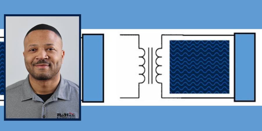
Stanley F. Rutkowski III Senior Applications Engineer RoMan Manufacturing, Inc.
Stanley F. Rutkowski III is the senior applications engineer at RoMan Manufacturing, Inc., working on electrical energy savings in resistance heating applications. Stanley has experience in welding, glass and furnace industries from R&D, design, and application standpoints. For more than 15 years, his focus has been on energy savings applications in industrial heating applications.
As heat treating facilities strive for energy efficiency and reliability, investing in power improvements can move a company toward sustainable operations. In this Controls Cornerinstallment, Brian K. Turner of RoMan Manufacturing, Inc. compares real power factor and displacement power factor in the efficiency and electrical performance of vacuum furnaces.
En el contexto de los hornos de vacío, el factor de potencia real y el factor de potencia de desplazamiento son conceptos claves en relación a la eficiencia y el comportamiento tanto de la fuente de energía eléctrica como de la carga del horno. A continuación, una comparación entre los dos factores.
1. El factor de potencia real (PF, por sus siglas en inglés)
Definición: El factor de potencia real es la relación entre la potencia real (potencia activa, P, medida en vatios) y la potencia aparente (S, medida en voltamperios). Da cuenta tanto del desplazamiento de fase como de la distorsión armónica.
Relevancia para hornos de vacío:
Los hornos de vacío, en particular los que funcionan con calentamiento por inducción, con frecuencia generan cargas no lineales debido a la operación de la electrónica de potencia.
Las cargas no lineales conllevan armónicos que distorsionan la forma de onda de la corriente generando una disminución en el factor de potencia real.
Un bajo factor de potencia real es indicador de ineficiencia ya que el sistema se ve obligado a aumentar el consumo de potencia aparente para generar la potencia real que se requiere.
2. El factor de potencia de desplazamiento (DPF, por sus siglas en inglés)
Definición: El factor de potencia de desplazamiento es el coseno del ángulo (ϕ) entre dos componentes fundamentales: el voltaje y las formas de onda de la corriente.
Relevancia para hornos de vacío
En los hornos de vacío la esencia inductiva de los componentes (p.ej., los transformadores y las cargas inductivas) genera un factor de potencia de retardo que se ve reflejado en el DPF.
Un bajo factor de potencia de desplazamiento (es decir, con retardo importante) implica demandas significativas para el sistema en cuanto a potencia reactiva, lo que a su vez afecta el tamaño de los transformadores y del equipo de distribución de energía.
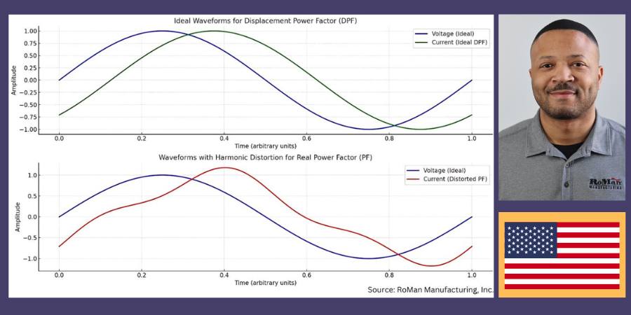
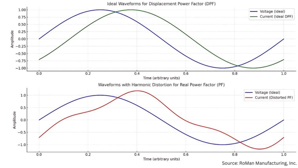
Tabla superior: DPF – Condiciones ideales
La forma de onda sinusoidal verde representa la corriente en un escenario con factor de desplazamiento de potencia ideal en el que interviene únicamente el desplazamiento de fase (ϕ) entre el voltaje (curva azul) y la corriente.
Las formas de onda se ven limpias y sinusoidales, indicando la ausencia de distorsión armónica.
Tabla inferior: PF — Con distorsión armónica
La forma de onda roja representa la corriente con la intervención de la distorsión armónica, situación típica de sistemas con cargas no lineales, caso de los hornos de vacío.
Esta distorsión genera una disminución en el factor de potencia real frente al factor de potencia de desplazamiento, aún cuando no se haya modificado la relación en la fase fundamental.
Formas de onda que permiten visualizar el DPF vs. el PF en relación a voltaje y corriente
Efecto sobre el tamaño de transformadores y transformadores de distribución
Aumento en la demanda de potencia aparente
Un factor de potencia real disminuido (debido a los armónicos) implica que el transformador deberá manejar una mayor potencia aparente (S) sin importar que la potencia real (P) no haya cambiado. Esto puede aumentar los costos de capital al requerir transformadores más grandes.
Estrés térmico
Los armónicos llevan a pérdidas adicionales (por las corrientes inducidas y la histéresis) generando el sobrecalentamiento de los transformadores y disminuyendo la eficiencia y duración de los mismos.
Regulación de voltaje
Los armónicos distorsionan la forma de onda del voltaje, lo que podría afectar los equipos sensibles y obligar al uso de transformadores capaces de regular de manera más precisa el voltaje.
Penalización por consumo energético
Los proveedores del servicio de energía muchas veces aplican sanciones por un bajo factor de potencia real, con lo que buscan incentivar a los usuarios a mejorar la calidad de la potencia mediante el uso de filtros armónicos o corrección del factor de potencia.
Conclusión
La revisión del factor de potencia en los hornos de vacío es de crítica importancia para lograr una mayor eficiencia y la reducción de los costos operativos. En su avance hacia la eficiencia y la fiabilidad energética, invertir en estas mejoras permitirá a las plantas de tratamiento térmico acercarse un paso más a la operatividad sostenible.
Traducido por: Shawna Blair
About the Author:
Brian Turner Sales Applications Engineer RoMan Manufacturing, Inc.
Brian K. Turner has been with RoMan Manufacturing, Inc., for more than 12 years. Most of that time has been spent managing the R&D Lab. In recent years, he has taken on the role as applications engineer, working with customers and their applications.
As heat treating facilities strive for energy efficiency and reliability, investing in power improvements can move a company toward sustainable operations. In this Controls Cornerinstallment, Brian K. Turner of RoMan Manufacturing, Inc. compares real power factor and displacement power factor in the efficiency and electrical performance of vacuum furnaces.
In the context of vacuum furnaces, real power factor and displacement power factor are key concepts related to the efficiency and electrical performance of the furnace’s power supply and load. Here’s a comparison:
1. Real Power Factor (PF)
Definition: Real power factor is the ratio of real power (active power, P, measured in watts) to apparent power (S, measured in volt-amperes). It considers both the phase displacement and harmonic distortion.
Relevance to Vacuum Furnaces:
Vacuum furnaces, especially those using induction heating, often generate nonlinear loads due to the operation of power electronics.
Nonlinear loads introduce harmonics, which distort the current waveform, reducing the real power factor.
A low real power factor indicates inefficiency, as the system draws more apparent power for a given amount of real power.
2. Displacement Power Factor (DPF)
Definition: Displacement power factor is the cosine of the angle (ϕ) between the fundamental components of voltage and current waveforms. It ignores harmonic distortion and considers only the phase displacement caused by inductive or capacitive loads.
Relevance to Vacuum Furnaces
In vacuum furnaces, the inductive nature of components (e.g., transformers and inductive loads) causes a lagging power factor, which is reflected in the DPF.
A poor displacement power factor (e.g., heavily lagging) means the system has significant reactive power demands, affecting the sizing of transformers and power distribution equipment.
The above waveforms illustrate the difference between displacement power factor (DPF) and real power factor (PF) as they relate to current and voltage:
Top Chart: DPF — Ideal Conditions
The green sinusoidal waveform represents the current in an ideal displacement power factor scenario, where only phase displacement (ϕ) exists between the voltage (blue curve) and current.
The waveforms are clean and sinusoidal, indicating no harmonic distortion.
Bottom Chart: PF — With Harmonic Distortion
The red waveform represents the current with added harmonic distortion, typical in systems with nonlinear loads, like vacuum furnaces.
This distortion causes the real power factor to drop compared to the displacement power factor, even if the fundamental phase relationship is the same.
Waveforms that illustrate DPF vs. PF as it relates to voltage and current
Effects on Transformer and Utility Transformer Sizing
Increased Apparent Power Demand
A lower real power factor (due to harmonics) means the transformer must handle higher apparent power (S), even if the real power (P) is unchanged.
This can necessitate larger transformers, increasing capital costs.
Thermal Stress
Harmonics lead to additional losses (eddy currents and hysteresis), causing transformers to overheat and reducing their efficiency and lifespan.
Voltage Regulation Issues
Harmonics distort the voltage waveform, which can affect sensitive equipment and require transformers with tighter voltage regulation capabilities.
Utility Penalties
Utilities often impose penalties for low real power factor, incentivizing users to improve power quality through harmonic filters or power factor correction.
Conclusion
Addressing power factor in vacuum furnaces is crucial for improving efficiency and reducing operational costs. As heat treating facilities strive for energy efficiency and reliability, investing in these improvements is a step toward sustainable operations.
About the Author:
Brian Turner Sales Applications Engineer RoMan Manufacturing, Inc.
Brian K. Turner has been with RoMan Manufacturing, Inc., for more than 12 years. Most of that time has been spent managing the R&D Lab. In recent years, he has taken on the role as applications engineer, working with customers and their applications.
For more information: Contact Brian at bturner@romanmfg.com.
Processes that utilize electric-powered industrial heaters instead of fossil fuels will necessitate improved power consumption management. Therefore, advanced technologies in power management systems are critical, as in-house operations think about cost savings and electric power requirement compliance.
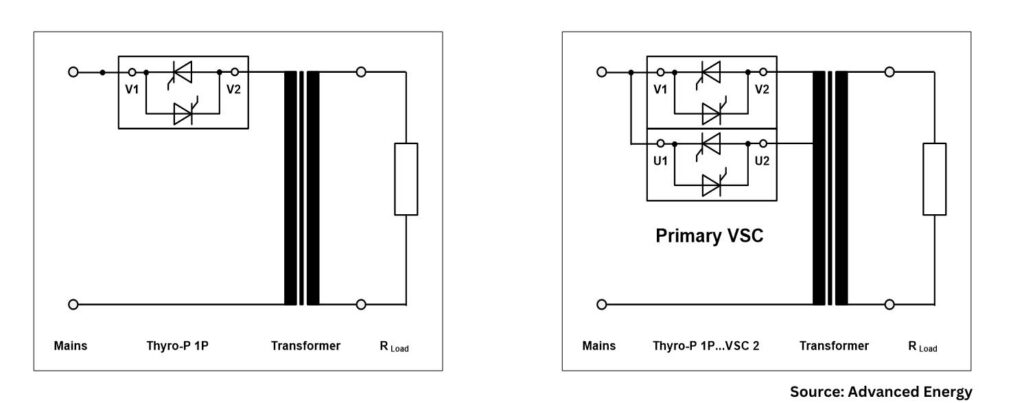
Janelle Coponen, senior product marketing program strategist, and Christian Schaffarra, director of research and development — Power Control Solutions’ Engineering Team, both of Advanced Energy, address the key to the discussion, SCRs and VSC, in this Technical Tuesday.Read more to understand how the reduction of harmonics allows operations to better manage energy consumption.
This informative piece was first released inHeat Treat Today’sJanuary 2025 Technologies To Watch in Heat Treating print edition.
Processes are increasingly converting to electric-powered industrial heaters instead of fossil fuels to improve process control and comply with the latest energy policies. This transition enables greater operational efficiencies but necessitates improved power consumption management by companies and their heat treat operations.
The integration of advanced technologies in power management systems is critical for both cost savings and to comply with electric power requirements. Among these technologies, silicon-controlled rectifiers (SCRs) and voltage sequence control (VSC) play a pivotal role in optimizing energy consumption. This article explores the significance of the reduction of harmonics by using a special energy-efficient mode to allow facilities to better manage and reduce their energy consumption.
What Are SCR Power Controllers?
Figure 1. SCR power controller
SCR power controllers regulate the power delivered to resistive or inductive loads. Unlike traditional mechanical switches, SCRs offer faster switching times and greater reliability. They are commonly used in applications requiring heating, melting, or bending such as heating elements, motors, and lighting systems.
These devices control electrical power, current, or voltage with high precision and reproducibility. They adjust the phase angle of the AC supply, allowing for finer control over the amount of power sent to the load. This reduces energy consumption and minimizes wear on the equipment, thereby extending its lifespan. Phase-angle firing is designed for high dynamic loads with small thermal inertia and allows for high control dynamic, soft and bump-less loading, and exact current-limit setting.
SCR power controllers produce high manufacturing quality and efficiency through:
Energy efficiency of approximately 99.6%
Power density of approx. 18 W/in3 (for 3-step VSC SCR)
High accuracy up to 1% for output power, 0.5% output voltage
Flexibility
EtherCAT Interface
Traditional SCR operation can be inefficient, especially under partial loads. An energy-efficient mode optimizes the SCR firing angle based on load requirements, reducing energy waste. By adapting to varying loads, these controllers improve system efficiency, lower energy costs, and reduce environmental impact.
Figure 2. Phas-angle firing control mode
Understanding Power Factor
Power factor (PF) is a critical component, representing the ratio of real load power (kW, the actual power consumed) to apparent load power (kVA, the total power supplied). It is a measure of how effectively electrical power is being converted into useful work output. A power factor of 1 (or 100%) indicates maximum efficiency, while lower values indicate wasted energy due to reactive power.
In many industrial settings, a low power factor can lead to higher electricity bills and additional charges from utility companies. Utilities must generate more power to compensate for the inefficiencies caused by reactive power, which does not perform useful work.
Benefits of Improved Power Factor and Reduced Harmonics
One significant advantage of using SCR power controllers is the ability to minimize harmonic distortion. Harmonics are voltage or current waveforms that deviate from the ideal sinusoidal wave, often caused by non-linear loads like electronic devices. These distortions can lead to overheating, equipment damage, and inefficiencies within the electrical system.
Figure 3. Power triangle
Reducing harmonics improves the overall efficiency of power systems and smoother equipment operation, which can prevent costly downtime. Additionally, improving power factor can result in financial savings by reducing energy loss, lowering demand charges, and increasing the capacity of existing electrical infrastructure.
This results in lower energy bills, less wasted energy, and better system reliability. Improved power factor can also help meet regulatory standards requiring specific power factor levels.
Special Energy-Efficient Mode, Voltage Sequence Control (VSC)
VSC complements SCR technology to enhance power system performance by managing voltage levels more effectively. It systematically sequences voltage application to loads, which improves power quality and extends the lifespan of equipment.
VSC is particularly beneficial for applications with inductive loads, where voltage management can significantly reduce inrush currents and mitigate harmonics. By integrating VSC with SCR technology, industries can harness the benefits of both systems, ensuring a stable and efficient power supply.
Combined Advantages of SCRs with Voltage Sequence Control
Improved energy efficiency: By optimizing firing angles and managing voltage sequences, facilities can achieve substantial reductions in energy consumption.
Cost savings: Lower energy usage translates directly into reduced operational costs, making these technologies economically attractive for businesses.
Enhanced equipment longevity: By reducing stress on electrical components through better voltage management, both SCRs and VSC can prolong the operational lifespan of machinery.
Environmental impact: Energy-efficient systems contribute to lower greenhouse gas emissions, aligning with global sustainability goals and regulatory standards.
Figure 4. Comparison phase-angle firing versus VSC
Advantages and Disadvantages of Using SCR in Voltage Sequence Control Mode
Here are several of the advantages:
Improved stability: Helps maintain voltage stability across the system, reducing the risk of voltage fluctuations and outages.
Enhanced performance: Optimizes the performance of electrical equipment by ensuring they operate within their rated voltage range, improving efficiency.
Protection against voltage imbalances: Monitors and adjusts for voltage imbalances in three-phase systems, which can prevent equipment damage and reduce wear.
Energy efficiency: By maintaining optimal voltage levels, VSC can lead to energy savings and lower operational costs.
Automated control: Often incorporates automation, allowing for real-time adjustments without manual intervention, thus improving response times.
Lowest level of harmonics: VSCs can help minimize harmonic distortion in electrical systems.
Lowest level of reactive power: The specific control design of the VSC can significantly impact the minimum achievable reactive power level, even in a weak grid.
Figure 5a. Standard circuit VAR (phase angle) / Figure 5b. VSC circuit
Compare with a few disadvantages:
Large footprint: Larger power controller footprint versus standard SCR power control system.
Initial cost: The initial investment in VSC systems and related technology can be higher, but payback time is less than a year.
Conclusion
Figure 6. Power factor over outpower in VAR (phase angle) blue line vs. VSC red line
In-house heat treat operations aiming for greater efficiency and cost reduction can benefit from VSC, the energy-efficient mode for SCR power controllers. By enhancing power factor and reducing harmonics, these devices optimize energy use and support sustainable, cost-effective operations. Adopting such technologies leads to significant improvements in industrial power consumption and enhanced savings for end users.
About the Author:
Janelle Coponen Senior Product Marketing Program Strategist Advanced Energy
With more than 21 years of experience in the industrial and energy sectors, Janelle Coponen bridges the gap between technical solutions and market needs. At Advanced Energy, she works alongside engineering teams to translate complex technologies into market ready strategies ensuring alignment between engineering innovations and business objectives.
Christian Schaffarra Director of Research and Development Power Control Solutions’ Engineering Team Advanced Energy
With more than 30 years of experience, Christian Schaffarra leads a research team dedicated to developing and advancing innovative power control technologies, ensuring optimal performance and reliability. He has a deep understanding of both the technical and marketing requirements that drive successful product development and engineered solutions.
If you work in a standards-driven industry, you may already feel the imperative of digitalization. In today’s Technical Tuesday, Mike Loepke, head of Nitrex Software & Digitalization, posits how, even if you aren’t necessitated to track compliance digitally, you are probably looking to synthesize and leverage the strengths of multiple advanced operations — furnace and process record-keeping, knowledge of furnace past operations, juggling different new equipment capabilities — across just one platform. In other words, you are looking to bring digitalization system management to your operations.
This informative piece was first released inHeat Treat Today’sDecember 2024 Medical & Energy Heat Treat print edition.
The Future of Heat Treatment Relies on Digitalization
The ultimate goal for heat treaters, whether commercial or captive, is to uphold the quality of their product and meet client expectations while remaining profitable. Digitalization supports these efforts as it synthesizes and presents detailed, transparent, and accessible data that allows heat treaters to better manage their equipment, processes, and product quality. In addition, the collection of detailed information can serve as a database of knowledge to be used by the next generation of heat treaters, supporting future viability and advancement in the field.
There are necessary steps to take to establish a digital solution and essential components to look for when choosing a software platform that assists heat treaters in optimizing equipment and processes, effectively creating the digitalization of the heat treat operations. Let’s explore these now.
How Digitalization Optimizes Heat Treatment Processes
Digitalization in the heat treatment industry relies on the integration of industrial internet of things (IIoT) technologies with traditional and modern heat treatment processes. Using enabling devices such as sensors, modern connectivity methods, analytics, machine learning, and IIoT software platforms, it is possible for heat treaters to collect and process data that, after analysis, drives informed decisions to optimize equipment, processes, and product quality. To put a finer point on it, digitalization occurs when a manufacturing system is digitally integrated to capture and preserve human experience and knowledge, forming a holistic virtual representation of heat treat operations.
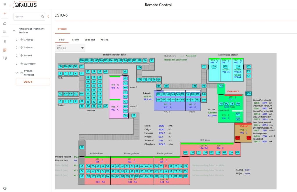
Figure 1. QMULUS Shop Layout enables visual inspection of the current production status, the
location of goods and parts, as well as the real-time status of assets and their ongoing processes. Source: Nitrex
While digitalization varies from industry to industry and plant to plant, there are some common ways in which heat treaters can employ digital technologies to build such a system. Firstly, digitally integrated solutions can optimize process management and control. For example, when a sensor detects a temperature anomaly during a heat treatment process, the integrated software platform picks up that reading, analyzes it in real time, recognizes it as an error based on historical data or programmed parameters, and alerts the operator.
This integration also facilitates predictive, condition-based maintenance. For example, if collected data and analysis suggests that a furnace is behaving abnormally, the system can automatically generate a work order along with a list of potential failure causes, so that a technician can troubleshoot, identify, and correct small issues — such as a failing thermocouple — before they impact quality or result in equipment failure. By addressing these proactively, heat treaters can avoid extended periods of costly unplanned downtime and ensure continuous operation.
Secondly, artificial intelligence through machine learning plays a crucial role in optimizing quality control in a digitalized system. By analyzing data collected during heat treating processes, it learns to detect patterns and identify anomalies. As in the examples above, this capability enables the system to identify deviations from the desired outcomes, allowing heat treaters to quickly rectify any issues before they impact quality.
Figure 2. The heart of the IIoT data platform needs to be thoughtfully planned and designed. Illustrated are 5
steps to follow to ensure the cloud data system properly engages with the data generated from your specific
heat treat operations, ultimately delivering actionable insights. Step 1 depicts the various data sources;
Step 2 shows the data transformation, integration, and processing stages; Step 3 highlights the central
QMULUS database where data is indexed and organized; and Steps 4 and 5 demonstrate how data is further
processed, distributed, and accessed by different end-users. Source: Nitrex
Thirdly, algorithms can be programmed into a comprehensive management system to identify the most energy-efficient operating conditions for the heat treating process, helping heat treaters reduce their carbon footprint, minimize energy costs, and comply with sustainability goals.
In addition to these types of operational advantages, digitalization technologies can also be used to create a database of knowledge before experienced operators and experts leave the workforce. Traditionally, a handful of experts in the plant oversee the furnaces and equipment and understand how to best control and maintain them based on experience. However, passing down this knowledge to the next generation of heat treaters can take years, which may not be possible due to a company’s workflow demands and cost pressures. Digitalization addresses this challenge by creating a streamlined and accessible database of knowledge, offering less experienced operators and technicians immediate access to detailed information about what may be happening in the equipment or process for an issue at hand. This ensures that essential insights are not lost and enables quicker problem-solving and decision-making on the shop floor.
Making the Digitalization Transformation
While digitalization presents obvious advantages, the heat treatment industry, often conservative in its approach to technology, has some initial work and investment required before realizing the full benefits.
Going “paperless” in order to unlock the full potential of the available data is an important first step. All reports, histories, drawings, and other paperwork associated with equipment, processes, maintenance activities, product quality, and other relevant information should be digitized to provide a comprehensive view of both historical and current data.
Connectivity and integration between machine and higher-level systems are essential for effective data acquisition, monitoring, and remote control. SCADA systems, Manufacturing Execution Systems (MES), and other higher-level systems are rich sources of machine and process data. Gathering and analyzing this data can provide actionable insights that operators can use to make smarter decisions about the control and maintenance of equipment and processes.
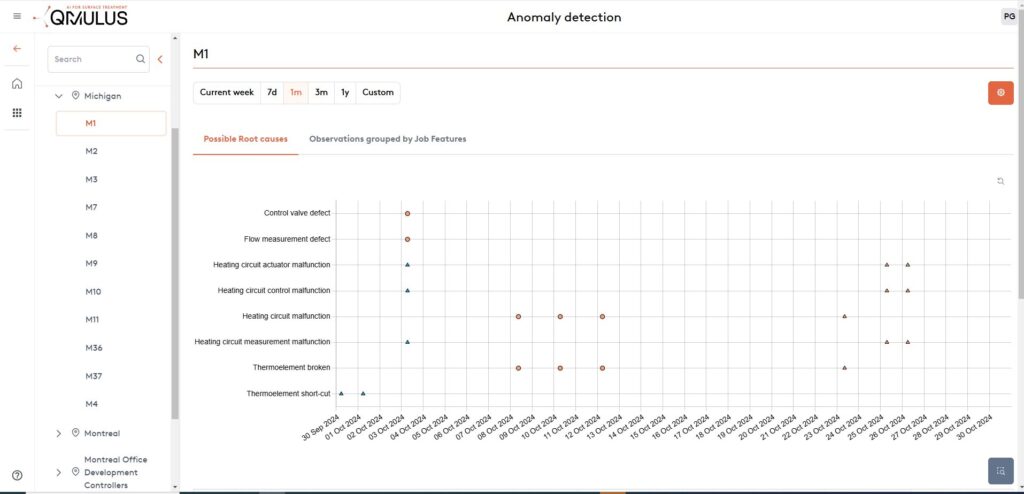
Figure 3. A comprehensive overview displays all detected control loop anomalies, indicating possible root causes as well as recommended actions. Incorporating feedback from the responsible maintenance personnel further improves accuracy and delivers more effective recommendations for future
occurrences. Source: Nitrex
Finally, just having data is not enough. The data must be accessible, transparent, and relevant to be valuable. Achieving a complete picture of all the collected data, known as data consolidation, is necessary.
To build an IIoT platform with a well-architectured data engine, heat treaters should begin by identifying and understanding the different sources of data provided by sensors and high-level systems. This involves integrating the data through interfaces adapted to the data type and source, as well as documenting the integrated data sources, data fields, and data streams. Next, a “data lake” should be created to store the collected raw data. From this foundation, a data warehouse can be established to store enriched or analyzed data, derived values, data models, and forecasts in an organized way. For heat treaters, this type of contextualized data might be grouped by parts, loads, or orders.
Once the data engine is in place, the information stored in the data warehouse must be presented in a way that makes sense to operators and technicians for them to make informed decisions for heat treatment processes. To facilitate this, a universal data interface should be considered.
Building from this well-architectured data engine, the IIoT platform can then be expanded with statistical analytics, remote monitoring, KPI tracking, machine learning, artificial intelligence, and other applications to optimize processes and increase profitability.
What Heat Treaters Need in a Digitalization Solution
Harnessing modern technologies tomake digitalization a reality presents heat treaters with the opportunity to implement a solution based on a complete and well documented data system. It also means that the solution creates a holistic solution to data analysis, interpretation, reporting, and action that supports the real-world actions of heat treaters on the plant floor and in the office.
For this reason, a digitalization solution that has cloud and on-premises allows real-time access to analysis and alert messages for operators on the floor as well as managers who are away from the plant, ensuring quick problem-solving and maximum uptime in the event of process or machine issues.
Additionally, heat treaters should look for a solution that offers the freedom to integrate all the various platforms and equipment from which data are gathered from. These may include relevant machinery and production data from the shop floor as well as third-party and custom controllers. This flexibility to synthesize information from multiple sources will ensure the digitalization efforts lead to a comprehensive solution with actionable process overviews, recipe control, batch tracking, and other customization options.
To further this intent of a holistic solution, heat treaters should consider various data capabilities with different portal views, such as a manufacturer portal, a plant portal, and a client portal. However, considering the historic value of a comprehensive software solution, it may be worthwhile to consider how each user could transfer direct feedback and add new rules into the system, creating a repository of knowledge that bridges the knowledge of outgoing generations to future heat treaters.
Finally, any platform that directs the digitalization of a plant must prioritize robust security measures. Several features to look for are:
enhanced encryption standards to keep data confidential and tamper-proof during transmission and storage;
secure protocols based on industry best practices to safeguard data integrity;
a granular access control system (ACS) to allow IT administrators to define and manage user permissions of authorized personnel, thereby minimizing the risk of data breaches and unauthorized data manipulation; and
intrusion detection and prevention systems to continuously monitor network and system activities, enabling instant identification and mitigation of suspicious behavior. This serves as an additional layer of defense against potential cyber threats.
Beyond the software setup, be sure to use best practices by conducting regular security audits to assess the platform’s vulnerabilities and ensure compliance with evolving cybersecurity standards. While digitalization of heat treat operations may seem like a task for the next generation to complete, secure software options that integrate the hard work of digitizing plant activities can make this endeavor just a step away.
About the Author:
Mike Loepke Head of Nitrex Software & Digitalization Nitrex
Drawing from a background in Mathematics and Physics, coupled with extensive R&D experience and metallurgical modeling, Mike Loepke specializes in AI and process prediction. He has led Nitrex’s initiative in developing QMULUS, a pioneering IIoT cloud-based platform. Mike’s relentless pursuit of knowledge keeps him at the forefront of evolving technology.
In this installment of the Controls Corner, we are addressing inductance in a furnace heating system, and the critical role it plays in various industrial systems, including furnace load systems. Impedance acts as a measure of how much a circuit resists the flow of AC current. In this guest column, Brian Turner, sales applications engineer at RoMan Manufacturing, Inc., explains how impedance applies in electrical circuits.
Inductance is a fundamental concept in electrical engineering, and it plays a critical role in various industrial systems, including furnace load systems. In furnaces used for heating, inductance is a key factor influencing the system’s electrical performance, energy efficiency, and overall operational behavior.
To talk about inductance, let’s first address impedance and how it applies:
In electrical circuits, impedance refers to the total opposition to the flow of alternating current (AC), which is a combination of both resistance (from resistors) and reactance (from inductors), essentially acting as a measure of how much a circuit resists the flow of AC current, taking into account both the resistive component (like a resistor) and the reactive component (like an inductor at a specific frequency) within the circuit.
Load configuration, power source (IGBT, VRT, ERT) to the furnace feedthrough Source: RoMan Manufacturing Inc.
Inductance
Inductance is the property of an electrical conductor that opposes a change in the current flowing through it. It arises from the magnetic field generated around the conductor when an electric current passes through it. The unit of inductance is the Henry (H).
In an AC circuit, inductance creates a phenomenon known as inductive reactance, which resists the flow of current. Inductive reactance (XL) is given by the formula:
XL= 2πƒL
Where: • XL is the inductive reactance (in ohms) • f is the frequency of the AC supply (in hertz) • L is the inductance (in Henrys)
This reactance influences how the current behaves in the system, which is particularly important in furnace load systems where high current flows are common.
Resistance
Electrical resistance is the opposition that a material offers to the flow of electric current. It is measured in ohms (Ω) and depends on factors such as the material’s properties, its temperature, and the geometry of the conductor (length, cross-sectional area). In heating systems like vacuum furnaces, resistance is harnessed to convert electrical energy into heat through Joule heating (also known as resistive heating).
The relationship between electrical power, voltage, current, and resistance is governed by Ohm’s law:
V = IR
Where: • V is the voltage across the heating element(in volts) • I is the current through the element (inamperes) • R is the electrical resistance of theelement (in ohms)
The heat generated by the furnace’s heating elements is a function of the power dissipated in the resistance, given by the equation:
P = I2 x R
This shows that the heat produced is directly proportional to the resistance and the square of the current flowing through the heating elements
Close Couple
Reducing the material in the secondary* reduces resistance (HEAT = I2 x R)
Reducing the area in the secondary reduces inductive reactance increasing power factor
To be most efficient, use the shortest amount of conductor material from the electrical system secondary to the furnace feedthrough. Additionally, keep the distance between those conductors as small as possible.
Power Factor and Efficiency
Inductance in a furnace load system causes the current and voltage to be out of phase. This phase difference results in a lower power factor, which is a measure of how effectively the system converts electrical power into useful work. A lower power factor means that more apparent power (the combination of real power and reactive power) is required to achieve the same level of heating.
In practical terms, a furnace with a high inductive load will draw more current from the power supply for a given amount of heating, leading to increased energy losses and inefficiency.
In practical terms, a furnace with a high inductive load will draw more current from the power supply for a given amount of heating, leading to increased energy losses and inefficiency. Power factor correction techniques, such as the use of capacitors, are often employed to counteract the effects of inductance and improve system efficiency.
Conclusion
Inductance is a fundamental factor in the operation of furnace load systems, influencing everything from heating performance to energy efficiency and power quality. By understanding and managing inductance, furnace operators can optimize their systems for maximum performance while minimizing energy losses and operational costs. Controlling inductance is essential for ensuring that furnace load systems operate reliably and efficiently in demanding industrial environments.
*The connection from a vacuum power source to the furnace’s feedthroughs, this connection can be made using air-cooled cables, water-cooled cables, or copper bus.
About the Author:
Brian Turner Sales Applications Engineer RoMan Manufacturing, Inc.
Brian K. Turner has been with RoMan Manufacturing, Inc., for more than 12 years. Most of that time has been spent managing the R&D Lab. In recent years, he has taken on the role as applications engineer, working with customers and their applications.