
Ask The Heat Treat Doctor® has returned to bring sage advice to Heat Treat Today readers and to answer your questions about heat treating, brazing, sintering, and other types of thermal treatments as well as questions on metallurgy, equipment, and process-related issues. In this installment, Dan Herring explains how partial pressure atmospheres prevent evaporation and achieve bright, oxide-free parts in vacuum furnaces.
This informative piece was first released in Heat Treat Today’s December 2025 Annual Medical & Energy Heat Treat print edition.
Have questions or feedback? We’d love to hear from you — reach out to our editorial team at editor@heattreattoday.com.
Operating in vacuum can often lead to problems related to evaporation, that is, literally “boiling away” elements present in the materials being heat treated. This affects surface integrity, functionality, performance, and in some rare cases altering the chemical composition of the base (or filler) metal.
One way to overcome this problem is to introduce a gas partial pressure higher than that of the material’s vapor pressure. Different gas choices, introduction methods, and controls are available to the heat treater. The natural question is, how and when should they be used? Let’s learn more.
What is Partial Pressure?
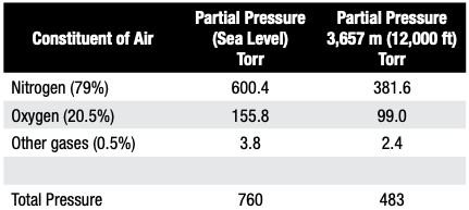
In simplest terms, the partial pressure of a gas introduced into a vacuum furnace is the force exerted by that gas (or gases) constrained in the vacuum vessel. If only a single gas is present, the partial pressure of the system is the same as the total pressure. For a multi-gas system, air is a good example to look at. At sea level with atmospheric pressure 760 torr (760 mm Hg) and at an altitude of 3,657 m (12,000 ft), the atmospheric pressure is only 483 Torr (Table A).
In vacuum systems, when the chamber atmosphere is evacuated to a high enough vacuum level — commonly between 10⁻³ Torr (0.1 micron) and 10⁻⁵ Torr (0.01 microns) — issues of evaporation are likely to occur during heat up and holding at temperature. As such, nitrogen or a truly inert gas is introduced below a predetermined temperature at a controlled rate to a fixed partial pressure range and then controlled within this range. One then isolates the high vacuum portion of the pumping system and employs bypass circuitry using the mechanical pump to introduce a continuous flow of gas equal to the pumping capacity (throughput) at the required operating pressure (Figure 1 below).
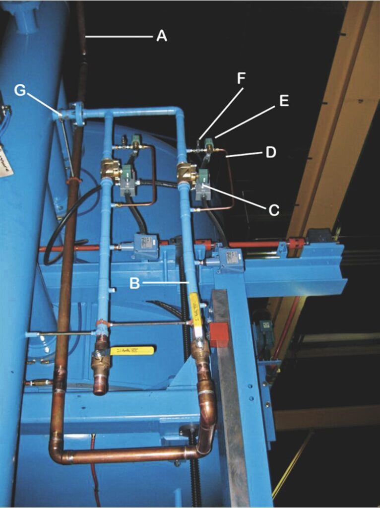
Figure 1. Typical partial pressure piping on a vacuum furnace
Key:
A: Incoming gas supply line
B: Backfill line
C: Quench solenoid
D: Partial pressure line
E: Partial pressure solenoid valve
F: Partial pressure (micrometer) needle value
G: Inlet into furnace
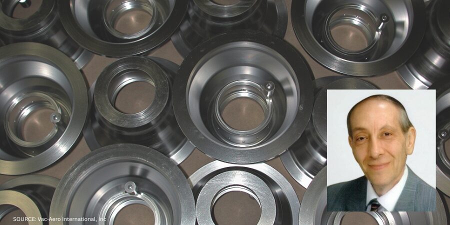
Source: Courtesy of Vac-Aero International
Why Do We Need to Use Partial Pressure in a Vacuum Furnace?
There is no hard and fast rule for partial pressure settings used for processing various materials in the heat treat industry. However, from a practical standpoint, there are two process considerations for determining partial pressure. The first is the metal-oxide reduction partial pressure. The partial pressure of oxygen at a given temperature determines the direction of the reaction and consequently whether the part is “bright” or “discolored” (oxidized). These values are typically in the range of 10⁻⁶ Torr to 10⁻² Torr. This is why materials like titanium alloys and superalloys must be processed at extremely low vacuum levels. The second consideration is the vaporization of metal at high temperature and hard vacuum. The metal solid-to-vapor partial pressures require higher pressures to avoid alloy depletion. These higher pressures often produce sufficient dilutions of contaminants to drive the reaction to be reducing.
What is often overlooked or misunderstood is that higher levels of partial pressure “dilute” any oxygen or water vapor partial pressure but still can produce oxide free “bright” parts at higher pressures. This dilution also occurs, for example when a retort is purged with nitrogen or argon to achieve clean parts. The oxygen partial pressure is reduced by dilution rather than by vacuum. In addition, it cannot be overemphasized that oxidation present on parts from exposure to the atmosphere and moisture absorbed by the furnace lining when the door is open are critical in running clean work. Oxidation occurs on heat up, but when the temperature is high enough and conditions are right, we can reverse the oxidation reaction so the parts will clean up. This is why it is harder to bright temper than to bright harden.
In batch vacuum furnaces, combination hardening and tempering cycles are used to take advantage of the furnace configuration in which parts stay in the furnace for the full process. Often, the same parts will discolor if tempered in the same furnace after they have been removed and the furnace exposed to air.
Also, a thorough understanding of the required component properties and material characteristics (e.g. alloy composition, grain size, hardenability response) is needed to design the final vacuum heat treat cycles and select the final partial pressure settings.
For example, stainless steels, tool steels, and more exotic alloys run in a vacuum furnace will benefit substantially from the use of partial pressure atmospheres. In most heat treat shops, partial pressure cycles begin around 760°C (1400°F) at pressure from 1–1.5 Torr (1000–1500 microns). This is primarily because chromium present in many of these materials and in our baskets/fixtures evaporates noticeably at temperatures and pressures within normal heat treatment ranges. At around 990°C (1800°F), chromium will vaporize rapidly as a function of both vacuum level and time. In general, the practical operating vacuum level for most materials is significantly above their equilibrium vapor pressures. It is also helpful at times to know the temperature at which individual elements exceed a critical (10⁻⁶ g/cm²-s) vaporization rate (Herring 2015).
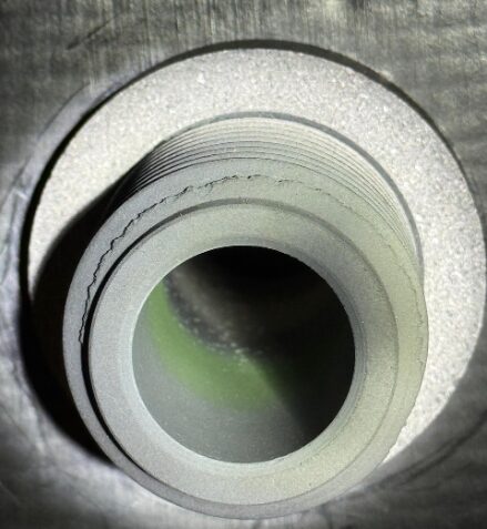
In practice, heat treaters often observe greenish discoloration (chromium oxide) on the interior of their vacuum furnaces (Figure 2), the result of chromium vapor reacting with air leaking into the hot zone. Otherwise, the evaporation deposit is bright and mirror-like. To avoid these types of deposits contaminating both the furnace and the parts run in it, an operating partial pressure between 1 Torr and 5 Torr (1,000 microns to 5,000 microns) is typical for parts that will boil away their elemental constituents.
Chromium Coloration
Heat treaters should be aware that although the most common color of chromium discoloration is green, the color is dependent on chromium’s oxidation state (Table B). For example, Cr (II) compounds typically appear blue, Cr (III) compounds appear green, and Cr (VI) compounds appear orange or red.
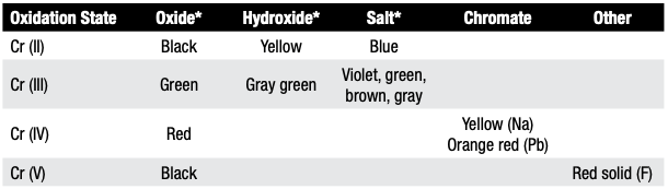
Table B. Oxidation Colors of Chromium and Chromium Compounds
Table B provides a more detailed breakdown of chromium’s oxidation states and associated colors.
Which Partial Pressure Gas(es) Can We Use?
Argon, nitrogen, and hydrogen are the most common partial pressure gases. Often, argon is preferred as it is a truly inert gas and tends to “sweep” the hot zone; that is, being a heavier molecule, it tends to reduce evaporation compared with nitrogen or hydrogen. Specialized applications, such as those in the electronics industry, may use helium or even neon (if an ionizing gas is needed). Gases having a minimum purity of 99.99% and a dew point of -60°C (-76°F) or lower should be specified.
Certain cautions are in order. For example, nitrogen may react with certain stainless steels and titanium bearing alloys resulting in surface nitriding. In the case of hydrogen, the normally near neutral vacuum atmosphere can be sharply shifted to a reducing atmosphere to prevent oxidation of sensitive process work or for furnace/fixture bakeout/cleanup cycles. Embrittlement by hydrogen is a concern for certain materials (e.g., Ti, Ta).
In Summary
Partial pressure atmospheres are required in many heat treating and brazing operations to achieve desired results. Introduction of the partial pressure gas into the furnace hot zone at one or more locations and controlling the partial pressure injection gas stream as a continuous flow, rather than trying to operate at a specific pressure, are critical considerations. The choice of partial pressure gas is also important both from a cost and quality standpoint.
References
Herring, Daniel H. 2014. Vacuum Heat Treatment. Vol. 1. Troy, MI: BNP Media.
Herring, Daniel H. 2015. Vacuum Heat Treatment. Vol. 2. Troy, MI: BNP Media.
Houghton, R., Jr. n.d. Private correspondence, Spectrum Thermal Processing.
Jones, W. R. 1997. “Partial Pressure Vacuum Processing – Part I and II.” Industrial Heating, September/October.
Jones, William. n.d. Private correspondence, Solar Atmospheres Inc.
Fabian, R., ed. 1993. Vacuum Technology: Practical Heat Treating and Brazing. Materials Park, OH: ASM International.
The Boeing Company. n.d. “Practical Vacuum Systems Design Course.”
About the Author

“The Heat Treat Doctor”
The HERRING GROUP, Inc.
Dan Herring has been in the industry for over 50 years and has gained vast experience in fields that include materials science, engineering, metallurgy, new product research, and many other areas. He is the author of six books and over 700 technical articles.
For more information: Contact Dan at dherring@heat-treat-doctor.com.
For more information about Dan’s books: see his page at the Heat Treat Store.