Brian Turner

Why PF and DPF Matter

As heat treating facilities strive for energy efficiency and reliability, investing in power improvements can move a company toward sustainable operations. In this Controls Corner installment, Brian K. Turner of RoMan Manufacturing, Inc. compares real power factor and displacement power factor in the efficiency and electrical performance of vacuum furnaces.

This informative piece was first released in Heat Treat Today’s February 2025 Air/Atmosphere Furnace Systems print edition.

To read the article in Spanish, click here.


In the context of vacuum furnaces, real power factor and displacement power factor are key concepts related to the efficiency and electrical performance of the furnace’s power supply and load. Here’s a comparison:

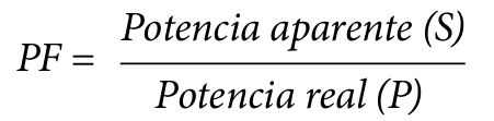
1. Real Power Factor (PF)

Definition: Real power factor is the ratio of real power (active power, P, measured in watts) to apparent power (S, measured in volt-amperes). It considers both the phase displacement and harmonic distortion.

Relevance to Vacuum Furnaces:

  • Vacuum furnaces, especially those using induction heating, often generate nonlinear loads due to the operation of power electronics.
  • Nonlinear loads introduce harmonics, which distort the current waveform, reducing the real power factor.
  • A low real power factor indicates inefficiency, as the system draws more apparent power for a given amount of real power.

2. Displacement Power Factor (DPF)

Definition: Displacement power factor is the cosine of the angle (ϕ) between the fundamental components of voltage and current waveforms. It ignores harmonic distortion and considers only the phase displacement caused by inductive or capacitive loads.

Relevance to Vacuum Furnaces

  • In vacuum furnaces, the inductive nature of components (e.g., transformers and inductive loads) causes a lagging power factor, which is reflected in the DPF.
  • A poor displacement power factor (e.g., heavily lagging) means the system has significant reactive power demands, affecting the sizing of transformers and power distribution equipment.

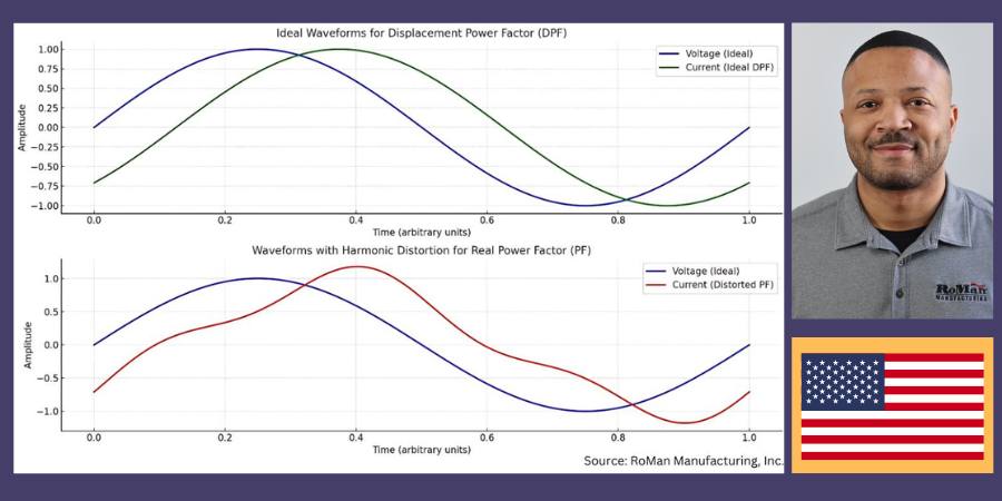
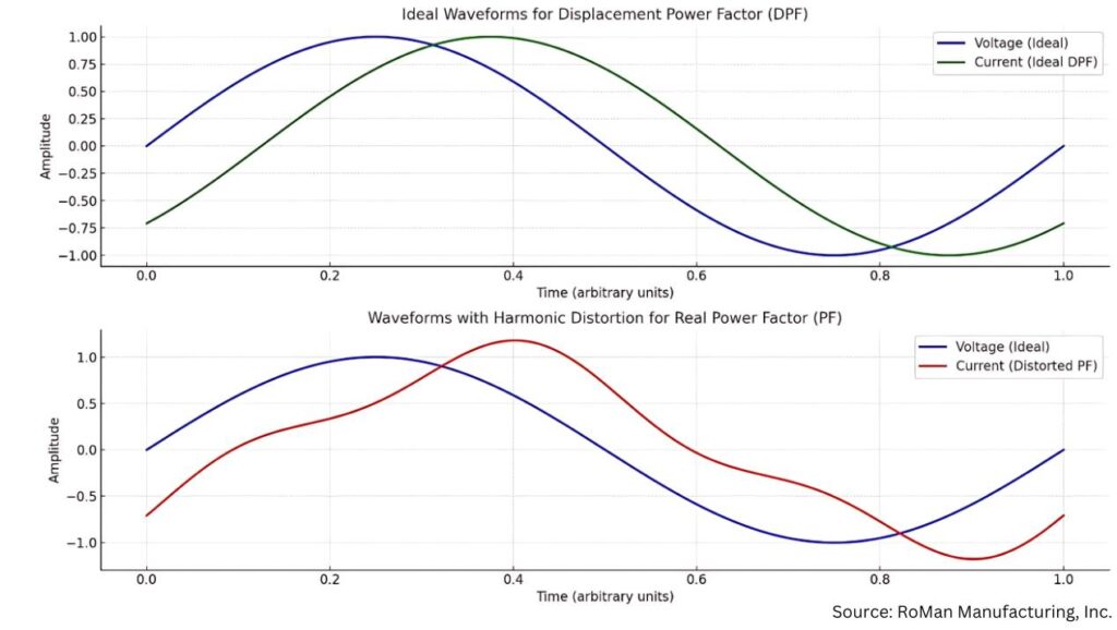
The above waveforms illustrate the difference between displacement power factor (DPF) and real power factor (PF) as they relate to current and voltage:

Top Chart: DPF — Ideal Conditions

  • The green sinusoidal waveform represents the current in an ideal displacement power factor scenario, where only phase displacement (ϕ) exists between the voltage (blue curve) and current.
  • The waveforms are clean and sinusoidal, indicating no harmonic distortion.

Bottom Chart: PF — With Harmonic Distortion

  • The red waveform represents the current with added harmonic distortion, typical in systems with nonlinear loads, like vacuum furnaces.
  • This distortion causes the real power factor to drop compared to the displacement power factor, even if the fundamental phase relationship is the same.
Waveforms that illustrate DPF vs. PF as it relates to voltage and current

Effects on Transformer and Utility Transformer Sizing

Increased Apparent Power Demand

  • A lower real power factor (due to harmonics) means the transformer must handle higher apparent power (S), even if the real power (P) is unchanged.
  • This can necessitate larger transformers, increasing capital costs.

Thermal Stress

  • Harmonics lead to additional losses (eddy currents and hysteresis), causing transformers to overheat and reducing their efficiency and lifespan.

Voltage Regulation Issues

  • Harmonics distort the voltage waveform, which can affect sensitive equipment and require transformers with tighter voltage regulation capabilities.

Utility Penalties

  • Utilities often impose penalties for low real power factor, incentivizing users to improve power quality through harmonic filters or power factor correction.

Conclusion

Addressing power factor in vacuum furnaces is crucial for improving efficiency and reducing operational costs. As heat treating facilities strive for energy efficiency and reliability, investing in these improvements is a step toward sustainable operations.

About the Author:

Brian Turner
Sales Applications Engineer
RoMan Manufacturing, Inc.

Brian K. Turner has been with RoMan Manufacturing, Inc., for more than 12 years. Most of that time has been spent managing the R&D Lab. In recent years, he has taken on the role as applications engineer, working with customers and their applications.

For more information: Contact Brian at bturner@romanmfg.com.


Why PF and DPF Matter Read More »

El PF y el DPF: ¿importan?

As heat treating facilities strive for energy efficiency and reliability, investing in power improvements can move a company toward sustainable operations. In this Controls Corner installment, Brian K. Turner of RoMan Manufacturing, Inc. compares real power factor and displacement power factor in the efficiency and electrical performance of vacuum furnaces.

This informative piece was first released in Heat Treat Today’s February 2025 Air/Atmosphere Furnace Systems print edition.

To read the article in English, click here.


En el contexto de los hornos de vacío, el factor de potencia real y el factor de potencia de desplazamiento son conceptos claves en relación a la eficiencia y el comportamiento tanto de la fuente de energía eléctrica como de la carga del horno. A continuación, una comparación entre los dos factores.

1. El factor de potencia real (PF, por sus siglas en inglés)

Definición: El factor de potencia real es la relación entre la potencia real (potencia activa, P, medida en vatios) y la potencia aparente (S, medida en voltamperios). Da cuenta tanto del desplazamiento de fase como de la distorsión armónica.

Relevancia para hornos de vacío:

  • Los hornos de vacío, en particular los que funcionan con calentamiento por inducción, con frecuencia generan cargas no lineales debido a la operación de la electrónica de potencia.
  • Las cargas no lineales conllevan armónicos que distorsionan la forma de onda de la corriente generando una disminución en el factor de potencia real.
  • Un bajo factor de potencia real es indicador de ineficiencia ya que el sistema se ve obligado a aumentar el consumo de potencia aparente para generar la potencia real que se requiere.

2. El factor de potencia de desplazamiento (DPF, por sus siglas en inglés)

Definición: El factor de potencia de desplazamiento es el coseno del ángulo (ϕ) entre dos componentes fundamentales: el voltaje y las formas de onda de la corriente.

Relevancia para hornos de vacío

  • En los hornos de vacío la esencia inductiva de los componentes (p.ej., los transformadores y las cargas inductivas) genera un factor de potencia de retardo que se ve reflejado en el DPF.
  • Un bajo factor de potencia de desplazamiento (es decir, con retardo importante) implica demandas significativas para el sistema en cuanto a potencia reactiva, lo que a su vez afecta el tamaño de los transformadores y del equipo de distribución de energía.

Tabla superior: DPF – Condiciones ideales

  • La forma de onda sinusoidal verde representa la corriente en un escenario con factor de desplazamiento de potencia ideal en el que interviene únicamente el desplazamiento de fase (ϕ) entre el voltaje (curva azul) y la corriente.
  • Las formas de onda se ven limpias y sinusoidales, indicando la ausencia de distorsión armónica.

Tabla inferior: PF — Con distorsión armónica

  • La forma de onda roja representa la corriente con la intervención de la distorsión armónica, situación típica de sistemas con cargas no lineales, caso de los hornos de vacío.
  • Esta distorsión genera una disminución en el factor de potencia real frente al factor de potencia de desplazamiento, aún cuando no se haya modificado la relación en la fase fundamental.
Formas de onda que permiten visualizar el DPF vs. el PF en relación a voltaje y corriente

Efecto sobre el tamaño de transformadores y transformadores de distribución

Aumento en la demanda de potencia aparente

  • Un factor de potencia real disminuido (debido a los armónicos) implica que el transformador deberá manejar una mayor potencia aparente (S) sin importar que la potencia real (P) no haya cambiado. Esto puede aumentar los costos de capital al requerir transformadores más grandes.

Estrés térmico

  • Los armónicos llevan a pérdidas adicionales (por las corrientes inducidas y la histéresis) generando el sobrecalentamiento de los transformadores y disminuyendo la eficiencia y duración de los mismos.

Regulación de voltaje

  • Los armónicos distorsionan la forma de onda del voltaje, lo que podría afectar los equipos sensibles y obligar al uso de transformadores capaces de regular de manera más precisa el voltaje.

Penalización por consumo energético

  • Los proveedores del servicio de energía muchas veces aplican sanciones por un bajo factor de potencia real, con lo que buscan incentivar a los usuarios a mejorar la calidad de la potencia mediante el uso de filtros armónicos o corrección del factor de potencia.

Conclusión

La revisión del factor de potencia en los hornos de vacío es de crítica importancia para lograr una mayor eficiencia y la reducción de los costos operativos. En su avance hacia la eficiencia y la fiabilidad energética, invertir en estas mejoras permitirá a las plantas de tratamiento térmico acercarse un paso más a la operatividad sostenible.

Traducido por: Shawna Blair

About the Author:

Brian Turner
Sales Applications Engineer
RoMan Manufacturing, Inc.

Brian K. Turner has been with RoMan Manufacturing, Inc., for more than 12 years. Most of that time has been spent managing the R&D Lab. In recent years, he has taken on the role as applications engineer, working with customers and their applications.

Para contactar a Brian: bturner@romanmfg.com.


El PF y el DPF: ¿importan? Read More »

Understanding Inductance in a Furnace Heating System

In this installment of the Controls Corner, we are addressing inductance in a furnace heating system, and the critical role it plays in various industrial systems, including furnace load systems. Impedance acts as a measure of how much a circuit resists the flow of AC current. In this guest column, Brian Turner, sales applications engineer at RoMan Manufacturing, Inc., explains how impedance applies in electrical circuits.

This informative piece was first released in Heat Treat Today’s November 2024 Vacuum Heat Treat print edition.


Inductance is a fundamental concept in electrical engineering, and it plays a critical role in various industrial systems, including furnace load systems. In furnaces used for heating, inductance is a key factor influencing the system’s electrical performance, energy efficiency, and overall operational behavior.

To talk about inductance, let’s first address impedance and how it applies:

In electrical circuits, impedance refers to the total opposition to the flow of alternating current (AC), which is a combination of both resistance (from resistors) and reactance (from inductors), essentially acting as a measure of how much a circuit resists the flow of AC current, taking into account both the resistive component (like a resistor) and the reactive component (like an inductor at a specific frequency) within the circuit.

Load configuration, power source (IGBT, VRT, ERT) to the furnace feedthrough
Source: RoMan Manufacturing Inc.

Inductance

Inductance is the property of an electrical conductor that opposes a change in the current flowing through it. It arises from the magnetic field generated around the conductor when an electric current passes through it. The unit of inductance is the Henry (H).

In an AC circuit, inductance creates a phenomenon known as inductive reactance, which resists the flow of current. Inductive reactance (XL) is given by the formula:

XL = 2πƒL

Where:
XL is the inductive reactance (in ohms)
f is the frequency of the AC supply (in hertz)
L is the inductance (in Henrys)

This reactance influences how the current behaves in the system, which is particularly important in furnace load systems where high current flows are common.

Resistance

Electrical resistance is the opposition that a material offers to the flow of electric current. It is measured in ohms (Ω) and depends on factors such as the material’s properties, its temperature, and the geometry of the conductor (length, cross-sectional area). In heating systems like vacuum furnaces, resistance is harnessed to convert electrical energy into heat through Joule heating (also known as resistive heating).

The relationship between electrical power, voltage, current, and resistance is governed by Ohm’s law:

V = IR

Where:
V is the voltage across the heating element(in volts)
I is the current through the element (inamperes)
R is the electrical resistance of theelement (in ohms)

The heat generated by the furnace’s heating elements is a function of the power dissipated in the resistance, given by the equation:

P = I2 x R

This shows that the heat produced is directly proportional to the resistance and the square of the current flowing through the heating elements

Close Couple

  • Reducing the material in the secondary* reduces resistance (HEAT = I2 x R)
  • Reducing the area in the secondary reduces inductive reactance increasing power factor

To be most efficient, use the shortest amount of conductor material from the electrical system secondary to the furnace feedthrough. Additionally, keep the distance between those conductors as small as possible.

Power Factor and Efficiency

Inductance in a furnace load system causes the current and voltage to be out of phase. This phase difference results in a lower power factor, which is a measure of how effectively the system converts electrical power into useful work. A lower power factor means that more apparent power (the combination of real power and reactive power) is required to achieve the same level of heating.

In practical terms, a furnace with a high inductive load will draw more current from the power supply for a given amount of heating, leading to increased energy losses and inefficiency.

In practical terms, a furnace with a high inductive load will draw more current from the power supply for a given amount of heating, leading to increased energy losses and inefficiency. Power factor correction techniques, such as the use of capacitors, are often employed to counteract the effects of inductance and improve system efficiency.

Conclusion

Inductance is a fundamental factor in the operation of furnace load systems, influencing everything from heating performance to energy efficiency and power quality. By understanding and managing inductance, furnace operators can optimize their systems for maximum performance while minimizing energy losses and operational costs. Controlling inductance is essential for ensuring that furnace load systems operate reliably and efficiently in demanding industrial environments.

*The connection from a vacuum power source to the furnace’s feedthroughs, this connection can be made using air-cooled cables, water-cooled cables, or copper bus.

About the Author:

Brian Turner
Sales Applications Engineer
RoMan Manufacturing, Inc.

Brian K. Turner has been with RoMan Manufacturing, Inc., for more than 12 years. Most of that time has been spent managing the R&D Lab. In recent years, he has taken on the role as applications engineer, working with customers and their applications.

For more informationContact Brian at bturner@romanmfg.com.


Understanding Inductance in a Furnace Heating System Read More »

Basic Definitions: Power Pathways in Vacuum Furnaces

Ever wish you had a map to follow when navigating your power source? In the following Technical Tuesday article, Brian Turner, sales applications engineer at RoMan Manufacturing, Inc., charts the route that power takes from the source to the load and back again in a vacuum furnace.


In a vacuum furnace, the journey from the load (the material being heat treated) to the incoming power involves a complex arrangement of components that deliver, control, and monitor electrical energy. Here’s a breakdown of the path from the source to the load and back to the source of incoming power of a vacuum furnace:

Load

The material — either an item or batch of items — that is undergoing heat treatment; can be metals, ceramics, or composites.

Heating Elements

Common materials for heating elements include graphite, molybdenum, or tungsten, depending on the temperature range and application.

Electrical Feedthrough

These are used to transmit electrical power or signals through the vacuum chamber wall. They often contain insulated conductors and connectors to ensure safe transmission without leaking air into the vacuum environment.

Conductors

The most common methods to connect power from a vacuum power source to the furnace’s feedthrough include air-cooled cables, water-cooled cables, and copper bus bar. Power efficiency can be improved when selecting the length, size, and area between conductors. This can be achieved by close coupling the power system to the electrical feedthroughs, reducing resistance and inductive reactance, and improving the power factor.

Machined Copper Bar
Source: RoMan Manufacturing, Inc.

Controlled Power Distribution Systems

The furnace market today generally relies on three primary types of control power distribution systems: VRT, SCR, and IGBT. Each of these technologies employs different methods to regulate the power input to the furnace, which in turn generates the required heat.

VRT (Variable Reactance Transformer)

  • The VRT controls AC voltage to the load, this is accomplished by a DC power controller that injects DC current into the reactor within the transformer.

SCR (Silicon Controlled Rectifier)

IGBT (Insulated-Gate Bipolar Transistor)

  • Balanced three-phase voltage is rectified through a bridge circuit to charge a capacitor in the DC bus. The IGBT network switches the DC bus at 1000Hz to control the AC output voltage to a Medium Frequency Direct Current (MFDC) power supply.
  • MFDC power supply transforms the AC voltage to a practical level and rectifies the secondary voltage (DC) to the heating circuit.
  • A line reactor on the incoming three-phase line mitigates harmonic content.

Control Systems

These systems manage the furnace’s operation, including driving the setpoint of the power system, temperature control, vacuum levels, and timing. They often consist of programmable logic controllers (PLCs), human-machine interfaces (HMIs), sensors, and other automation components.

Incoming Power

This is the origin of the furnace’s electrical energy, typically from a utility grid. It provides alternating current (AC), which is distributed and transformed within the furnace system to power all necessary components. In industrial settings, power companies usually charge for electricity based on several factors that reflect both the amount of electricity used and how it’s used. Some common charges/penalties are energy consumption (kWh), demand charges (kW), power factor penalties, and time-of-use (TOU) reactive power.

Conclusion

The careful arrangement of heating elements, electrical feedthroughs, conductors, and controlled power distribution systems allows for precise temperature control, ultimately impacting the quality of the processed material. Understanding the role of various control systems, such as VRT, SCR, IGBTs, and transformers is crucial for optimizing furnace performance and managing energy costs

About the Author:

Brian Turner
Sales Applications Engineer
RoMan Manufacturing, Inc.
Source: RoMan Manufacturing, Inc.

Brian K. Turner has been with RoMan Manufacturing, Inc., for more than 12 years. Most of that time has been spent managing the R&D Lab. In recent years, he has taken on the role as applications engineer, working with customers and their applications.

For more information: Contact Brian at bturner@romanmfg.com.


Find Heat Treating Products And Services When You Search On Heat Treat Buyers Guide.Com


Basic Definitions: Power Pathways in Vacuum Furnaces Read More »