Why Heat Matters and the Need for Speed
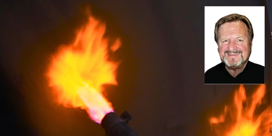
In this installment of Technical Tuesday, Jim Roberts of U.S. Ignition engages readers in a Combustion Corner editorial about the role of velocity in heat treating — breaking down how faster burner speeds create more turbulence in the furnace, which helps parts heat up faster and more evenly.
This editorial was first released in Heat Treat Today’s June 2026 6th Annual Buyers Guide Issue print edition.
A furnace guy walks into a heat treat plant and looks around. While it all looks calm and controlled, the agitation inside the furnaces is rampant.
So many times, we forget to slow down, look over our shoulders, and see all we’ve accomplished or learned. Combustion Corner series began with the intent to take a simple, almost primer-level look at what combustion-related issues the modern heat treater — furnace technicians, production managers, and really everybody involved in the process — may encounter.
The focus has been on burners and flame-related items. Occasionally, we get questions for an opinion on considering gas-fired versus electric furnaces or other similar questions. That’s dangerous ground to tread because so many different processes can use both. In fact in most cases, the method of heating is really moot to the process goal: Get heat delivered, cleanly, and all will be well with the parts and the process.
With that in mind, let’s take a peek at what really matters in heat treating. It’s the heat. Specifically, it’s how to get heat delivered as quickly as possible and with as much control as is possible. I know, kind of obvious that heat is important in heat treating. There are “four modes of heat transfer,” but we’ll just look at one of them today.
Convective Transfer
Convective transfer is an easy one because we see so many practical applications in our own homes. The new ovens in the modern home are often convection ovens and seemingly everybody has an air fryer. In the kitchen alone, you can see this how heat transfer increases can happen via convection increases. Take this principle to the shop floor and you can see how critical it is in processes that allow contact with flue gases or hot air.
We used to heat up the box of bricks, and once it got to the needed temperature for the metallurgy requirement, we would push in a basket of parts and wait for them to catch up to that temperature. The thermal mass of the load would literally suck the heat right out of the box, and the temperature would crash. Then, we’d wait for the temperature to stabilize. Once there, the old rules of time and temperature would apply.
But what if we wanted to speed up the process? What if we wanted more even temperature delivery and more temperature uniformity? The word that comes to mind in most burner intrinsic processes is velocity.
Velocity
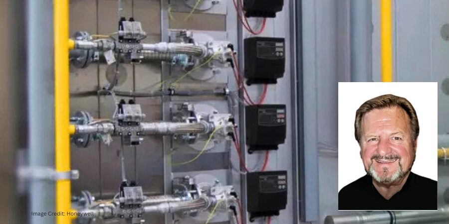
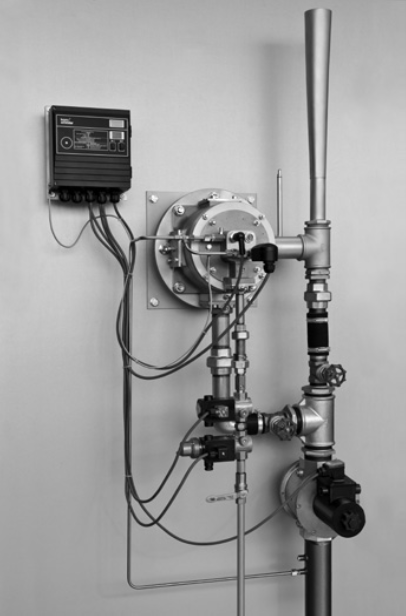
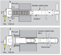
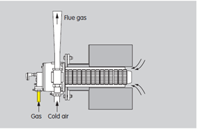
We talked about how some direct-fired burners are now designed to give fantastic exit velocities from the burner and into the furnace chamber. And when I say fantastic, it has to do with comparing what was an acceptable burner design back in the early days of industrial America when burner flame/flue gas exit velocity of direct-fired heat treating was like 40 MPH. New burners of today have exit velocities of almost 500 MPH!
Here is why it matters: Velocity will have a direct effect on the heat transfer, firstly by blasting into the “boundary layer” of gases that circulate around parts in the furnace. And most flue gases have been laminar in nature, but with this increased turbulence, the agitation of these gases allows more direct contact with the actual part.
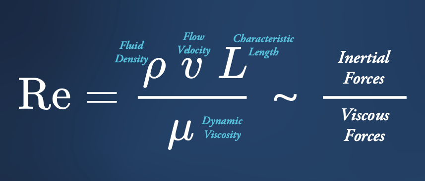
This increased turbulence results in a higher Reynolds number. The Reynolds number (Re) is a dimensionless quantity in fluid mechanics that predicts flow patterns — laminar (smooth) or turbulent (chaotic) — by calculating the ratio of inertial forces to viscous forces.
The word viscous reminds us that all things flowing around in the furnace are considered fluid from a scientific viewpoint. Interestingly, all this turbulence also results in greater mass transport. Remembering that the part or load has some mass, once it begins to heat up, it actually begins to emit heat as well. This mass transport mechanism is a result of the turbulence moving the heated molecules away from the surface of the part more quickly, which maintains a higher temperature differential, and again, increases heat transfer.
I guess what we are doing here is starting with velocity on a burner-level discussion, and we will discuss multiple methods and scientific quirks regarding the big picture — heat transfer. We will discuss some of the basics of heat transfer and explore comparisons between conduction, radiation, and convection, and more.
Till next time…
About The Author:

President
US Ignition
Jim Roberts president at U.S. Ignition, began his 45-year career in the burner and heat recovery industry focused on heat treating specifically in 1979. He worked for and helped start up WB Combustion in Hales Corners, Wisconsin. In 1985 he joined Eclipse Engineering in Rockford, IL, specializing in heat treating-related combustion equipment/burners. Inducted into the American Gas Association’s Hall of Flame for service in training gas company field managers, Jim is a former president of MTI and has contributed to countless seminars on fuel reduction and combustion-related practices.
For more information: Contact Jim Roberts at jim@usignition.com.

Why Heat Matters and the Need for Speed Read More »