


Ask The Heat Treat Doctor® has returned to bring sage advice to Heat Treat Today readers and to answer your questions about heat treating, brazing, sintering, and other types of thermal treatments as well as questions on metallurgy, equipment, and process-related issues. In this installment, Dan Herring explores the third part of his series on heat treatment guidelines, covering how to define and specify case depth, hardness values, and testing locations on prints, and how to choose the right hardness test method to get accurate repeatable results.
This informative piece was first released in Heat Treat Today’s November 2026 Annual Vacuum Heat Treating print edition.

If you have any comments or queries, on this article, let us know at editor@heattreattoday.com.
Para leer el artículo en español, haga clic aquí.
We continue our heat treatment series offering guidelines focused on “getting the job done right, the first time and every time” in the real world. Let’s learn more.
How We Achieve Our Goals
Here are a few more basic metallurgical and heat treatment guidelines that can, from a practical standpoint, help to avoid heat treatment issues (Herring 2014a, 2014b, 2014c).
Defining Terminology
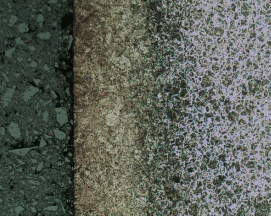
It is important to understand what we mean when we specify a heat treat requirement. For example, consider atmosphere gas carburizing. The technical definition for a carburized case depth is expressed in terms of carbon content:
- Total case depth: The depth at which the carbon content of the steel is 0.04% above the core carbon content of the steel. In other words, total case depth is the point at which differences in the chemical or physical properties of the case and core can no longer be distinguished (Figure 1). Many metallurgists determine the total case depth by (Nital) etching a steel sample and measuring the zone affected by the etchant.
- Effective case depth: The depth at which the carbon content of low-alloy steel is 0.40% and approximately 0.30% for medium alloy and high-alloy steels.
Since it is often time consuming and expensive to measure carbon concentration as a function of depth in a carburized component to determine case depth, other techniques are commonly used, such as microhardness. In certain situations involving very deep case depths, hardness can be measured on a test sample directly on the Rockwell “A” or “C” scales. The following definitions are used:
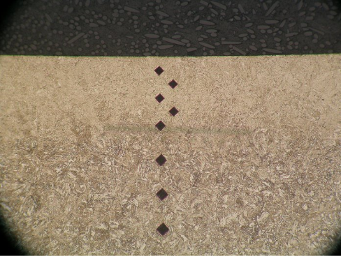
- Effective case depth (U.S.): The distance from the surface (in inches) to a point within the case where the hardness is 50 HRC (542 Knoop or 513 HV). This measurement is done on a cross-section by microhardness techniques with a Knoop or Vickers indenter (Figure 2). These values are then converted to Rockwell C hardness when a 500-gram-force load is used per ASTM E384 (latest revision). Interpolation is required to arrive at the proper case-depth value. The effective case depth depends on the carbon gradient and the case hardenability, but 50 HRC is typically equated to a carbon content of 0.40% in low-alloy steels and 0.30% in medium- and high-alloy steels.
- Effective case depth (international): The distance from the surface (in millimeters) to a point within the case where the hardness is 550 HV (approximately 52.5 HRC). This measurement is done by a Vickers microhardness method with a predefined load of 1 kilogram and is not converted to Rockwell C. The effective case depth still depends on the carbon gradient and the case hardenability. For highly alloyed case-hardening steels, the carbon content for 550 HV is typically in the range of 0.25- 0.30%. For medium-alloy grades, it is approximately 0.30-0.35% C, and for low-alloy steels, it is approximately 0.35-0.40% C.
Case-Depth Callouts on Prints
Case depth on engineering drawings should be stated as total case depth, effective case depth, or finished effective case depth after a defined amount of material is removed from the surface. It is important to note that if neither total nor effective case depth is specified, it should not be assumed that total case depth is intended (although at one time many years ago this was a commonly held belief).
A “rule of thumb” is often used to approximate the total case depth from the effective case depth. Given the effective case depth, the total case depth can be estimated by multiplying the effective case depth by 3/2. To determine the effective case depth from the total case depth, multiply the total case depth ⅔. The steel grade, chemistry, material hardenability, and case depth influence this rule.
Other important considerations include:
- Specify the condition of the part at the time of testing (as-quenched, as-tempered, after final grind).
- Specify the test procedure at each location and for each characteristic.
- State the maximum and minimum specification tolerance.
- Show the part print and specification to your test lab and part producer and check their interpretations of the specification against your requirements.
When specifying the required case-hardening heat treatment, it is important to define the process, the desired case depth range, and the hardness testing scale to evaluate the parts.
This is best illustrated in a case study where hardened light-duty bearings made of 1117 steel failed after being heat treated to a specification requiring a hardness of 58 HRC and a case depth of 0.015–0.020 inches. There are several technical concerns with the specification regarding process definition, case depth definition, and the unspecified hardness scale to measure case depth.
Hardness Values
When specifying the hardness range or tolerance for expected surface hardness values or core hardness, it is necessary to recognize the full range of hardenability of the specified steel at the point of interest on, or in, the part. The expected variation in surface hardness after induction or flame hardening can be determined by checking the high and low values of the carbon for the specific grade of steel versus the hardness values shown in the 99.9% martensite column in Table 1 (Part One). For example, SAE 1045 steel, with a carbon range of 0.43–0.50%, can achieve a fully martensitic as-quenched hardness of 57–60 HRC, while SAE 4140 steel, with a carbon range of 0.38–0.43%, can achieve only 55-57 HRC.
For through-hardening heat treatments, curves (c.f., Figure 1, Part Two) can be used with the Jominy hardenability data for the specific steel grade to predict the actual variation in surface or core hardness for a given steel and quenching situation. To predict the expected variation in core hardness at the center of a 13-mm (0.5-inch) section of 8620H, the center of the section when quenched in oil with good agitation (H = 0.35) will yield hardnesses equivalent to about the J3 position. From the Jominy hardenability data (c.f., Figure 2, Part Two), the hardness values at the J3 position are 32-44 HRC, or a 12 HRC point spread. This range of core hardness values would be the appropriate print specification given this specific situation.
Part Geometry
Total case depth and effective case depth can vary on a part that is uniformly heat treated due to section size, steel hardenability, and part geometry. Therefore, it is good practice to identify the critical area(s) where case depth or core hardness values are to be determined. This identification is still critical for gears where it is generally understood that the tests are to be at the pitch line or root diameter. For other parts, such as tubes, shafts, and parts having convex or concave spherical sections, it is very important to define the testing location. The effective case depth on a part having both a flat surface and concave surface can vary as much as 30% on a properly carburized part.
Hardness Testing
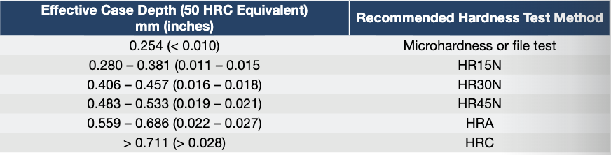
When specifying the surface hardness requirements for case hardened parts, care must be taken to specify the proper hardness scale to ensure that the case will support the test and that accurate hardness values can be obtained. There is a relationship between the hardness test method that can be used and the required minimum specified effective case depth (Table A).
Next time we will look at how to best determine process cycles, focusing on two of the more common case hardening methods, carburizing and carbonitriding.
References
Dossett, Jon. 2007. “Make Sure Your Specified Heat Treatment Is Achievable.” Heat Treating Progress (March/April).
Dossett, Jon. 2025. Private conversation.
Herring, Daniel H. 2014a. Atmosphere Heat Treatment. Vol. 1. Troy, MI: BNP Media Group II.
Herring, Daniel H. 2015b. Atmosphere Heat Treatment. Vol. 2. Troy, MI: BNP Media Group II.
Herring, Daniel H. 2014c. “Interpreting Carburized Case Depths, Part 1: Hardness Testing Methods.” Industrial Heating, July, 2014.
Herring, Daniel H. 2014d. “Interpreting Carburized Case Depths, Part 2: Methods for Measuring Case Depth.” Industrial Heating, August, 2014.
About the Author

“The Heat Treat Doctor®”
The HERRING GROUP, Inc.
Dan Herring has been in the industry for over 50 years and has gained vast experience in fields that include materials science, engineering, metallurgy, new product research, and many other areas. He is the author of six books and over 700 technical articles.
For more information: Contact Dan at dherring@heat-treat-doctor.com.
For more information about Dan’s books: see his page at the Heat Treat Store.