Automating the Brinell Hardness Tester In-House
![]()
Automating Brinell hardness testing could mean saving on expensive laboratories, as was the case for one oil tool industry manufacturer. Learn the basics of Brinell hardness testing, its strengths and weaknesses, and options for automation.
This Technical Tuesday article, written by Alex Austin, managing director of Foundrax Engineering Products Ltd., was originally published in Heat Treat Today’s December 2023 Medical and Energy Heat Treat print edition, both in English and in Spanish.
Brinell Hardness Testing: Strengths and Weaknesses

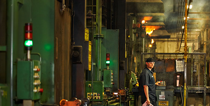
In many steelworks producing large forgings and billets, in numerous heat treatment companies, and near many factory lines producing components for safety-critical applications, you’ll find a Brinell hardness tester. These machines have been used all over the world for more than a century (the test was first demonstrated by its inventor, the Swedish metallurgist August Brinell, in 1900), determining metal hardness by means of a tungsten carbide indenter ball that leaves a dish-shaped indentation in the surface of the test material.
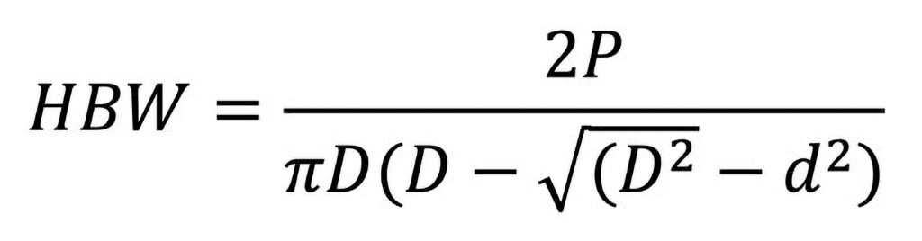
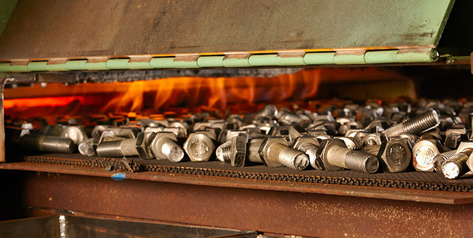
In the test, the material sample is placed on a rigid anvil, and the indenter descends onto it under loads ranging from 1 kg up to 3,000 kg, depending on the material. Indenters vary in diameter from 1 mm to 10 mm. Most tests use a 3,000 kg load and a 10 mm ball, and the standards always refer to this as “HBW 10/3000.” HBW stands for Hardness Brinell Wolfram, Wolfram being another name for the tungsten carbide the indenter ball is made from. After the (approximately) fifteen second indenting cycle, the indentation is measured across both its x and y axes, as a minimum, by a special calibrated microscope. The mean of the diameter readings is then fed into the Brinell equation.

Naturally, most technicians would rather not use that equation, so they look the indentation diameter up on a chart and “read across” to the derived hardness.
The great advantage of the Brinell test, when considered alongside other metal hardness testing methods, is that the large indentation diameter (typically between 2.4 mm and 6 mm) means the test result is generally unaffected by the grain structure of the metal. It also means that the surface of the test sample can be adequately prepared in just a few seconds with an angle grinder. For these reasons, the test is regarded by many as the “default” one for rough-surfaced and/or coarse-grained samples.
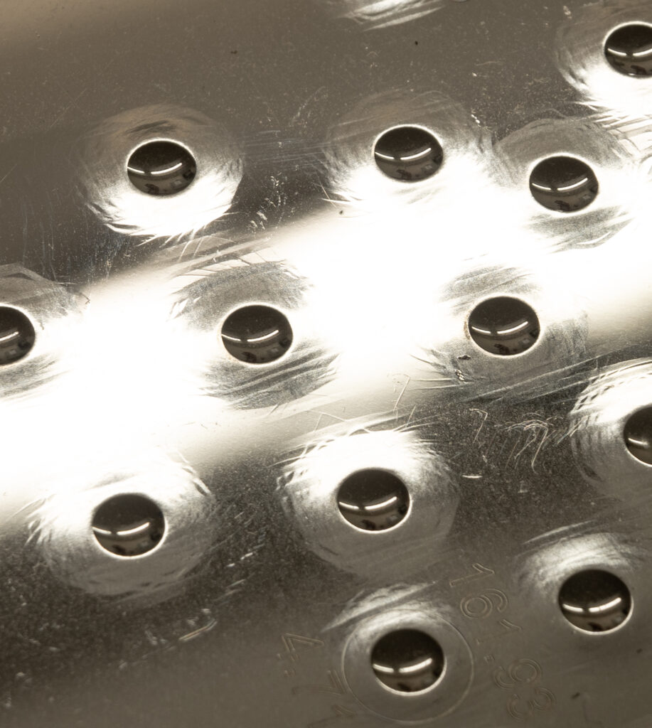
On the block in image (Figure 4), the distortion around the indentations can be seen very clearly.
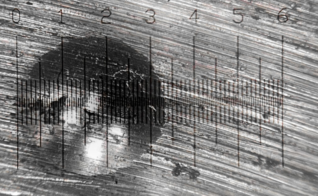
That seems pretty simple, but there are inherent weaknesses in the Brinell test: measuring the indentation. In our previous article (read it in Heat Treat Today’s August 2023 Automotive Heat Treat print edition), we used this image (Figure 2) to illustrate how difficult it could be to work out exactly where an indentation edge begins and ends.
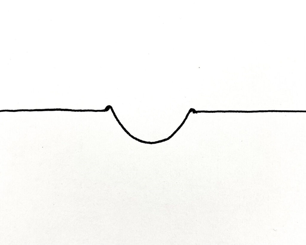
You might look at Figure 2 and think, “I’m pretty confident about where that indentation edge is,” but it’s trickier than it looks, because the process of indenting doesn’t just push material downwards; it also spreads it sideways, and you get a “pile up” around the rim of the indentation. The pile up may be difficult to see on hard material, or there may be a subtle “lip” inside the pile up that represents the true edge, but considered in cross-section, indentations look roughly like this simple sketch above (Figure 3).
The overhead light illuminates the “pile up” rim very clearly on some of those indentations as a highlight around the edge. Where, exactly, does the pile up end and the true edge of the indentation begin? Bear in mind that 0.2 mm can equal 20 hardness points. You could show an indentation to three experienced workshop technicians and receive three different answers to the diameter question, and this problem has been a challenge of the Brinell test from its inception. Special blocks are available for training technicians in measurement, but the problem of operator interpretation was such that, in some quarters, the Brinell test was regarded as a bit “rough and ready.” “Ok for the workshop but not for the lab,” was perhaps how it was once seen.
Why Automate the Brinell?
The first question to consider when looking at the automation of the Brinell test is the measurement system because this is the inherent weakness. There are, of course, applications where only narrow tolerances are acceptable, and disagreements can arise between customers and suppliers.
Over the years, certain manufacturers, who mill heat treated materials for the oil tool industry, confided to us that they were regularly using expensive testing laboratories because of clients disputing the hardness figures of their products. They had previously been using manual microscopes. Obviously, this has reputational, as well as financial, consequences. If a manual microscope is employed on raw materials at the goods-in-process stage and there’s an error reading the hardness, you could find at final machining that you have put a lot of time and effort into a part that, in the end, is too hard or soft for the intended application.
Manually manipulating the microscope may not be worth the effort, especially when even a diligent operator may read the result incorrectly. With an automatic Brinell microscope, however, there is the possibility of major time and cost savings.
4 Levels of Automation
#1 Beginnings of Brinell Automation
The first step in automating Brinell hardness testing began 40 years ago when the world’s first automatic measurement microscope hit the market. The system, still being regularly refined, was able to measure the diameter of the indentation across over 100 axes, calculate the mean, and determine the hardness in a split second. It can handle most surface irregularity, operate in poor lighting, and warns operators of unacceptable surface preparation. Additionally, its precision adjusts for spatial error when lining up with a graticule. Within a few years of launch, a major oil tool manufacturer’s quality chief recommended its use to his suppliers, and user uptake was rapid.
#2 Integrated Microscope Model
A further step in automation is to dispense with operator handling of the microscope entirely by the acquisition of a tester with an integrated microscope. The microscope mentioned above, for example, is a feature on several hardness testing machines. The heavy-duty indenter holder pivots away from its normal line of thrust at the end of the indenting cycle, allowing a supra-mounted camera to view the indentation. This is hugely advantageous: no separate apparatus near the test machine, reduced handling time, and thus, much faster testing overall. Results from such machines are displayed next to the control panel and quickly uploadable to company quality systems.
#3 Dispensing of Manual Operations
Another automation option is to dispense with a hand-cranked anvil capstan and purchase a tester with a fixed anvil and movable test head. The technician is not required to manually raise and lower the anvil to allow for variations in the size of sample. Instead, the test head automatically “takes up” the space and also clamps the test piece very securely in place during the test cycle.
#4 Incorporate Custom Hardness Tester in Production Line
The fourth, and obviously most dramatic, automation step to consider is incorporating a custom-designed hardness tester into the production line. In some industries, this is essential. Large billets and forgings can’t be lifted into the jaws of a benchtop or floor-standing Brinell tester; so, for highly accurate testing of such items, a larger machine is required (Figure 5).
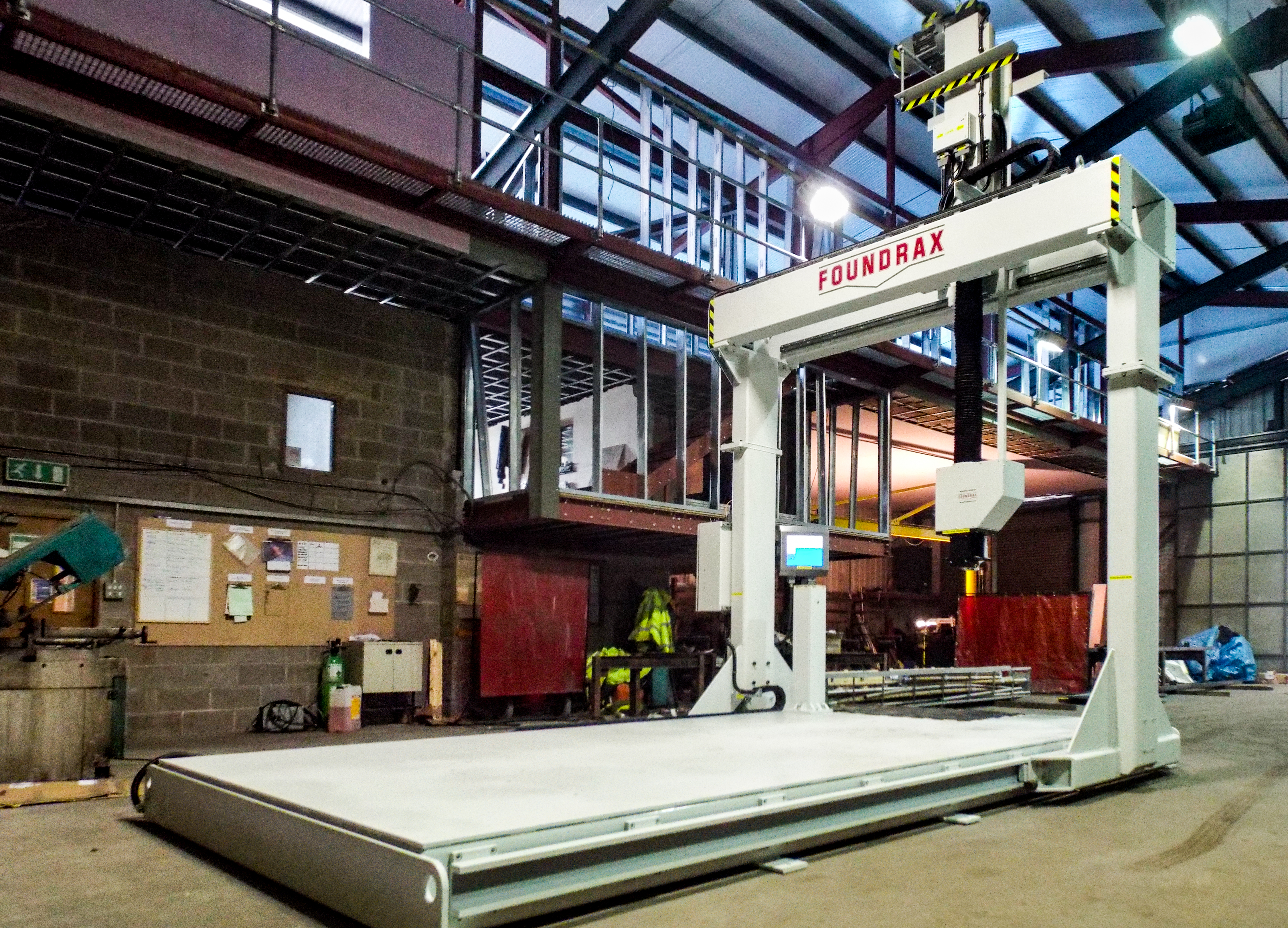
The whole gantry moves on one axis of travel while the test head moves perpendicular to that and, of course, up and down. This provides the full x, y, z movement. Large samples are maneuvered on and off by crane. The test head assembly incorporates the automatic microscope and results are displayed on a screen beside the control panel. Test results can be instantly uploaded to factory quality systems. The head assembly can also incorporate a milling tool for surface preparation!
With any decision to purchase plant and machinery equipment, some form of cost-benefit analysis is worthwhile. Clearly, if you’re doing a significant amount of business annually with a customer who is threatening to cease contracting with you because your hardness measurements are wrong too often, then the decision to buy an automatic microscope is not a difficult one. If staff are on overtime because mandatory hardness testing is adding too much time to production schedules, then a heavy-duty production machine with automatic microscope, movable test head, and sample clamp will pay for itself easily.
One thing is certain: Every automation option in Brinell testing increases accuracy and saves time.
About the Author
Alex Austin has been the managing director of Foundrax Engineering Products Ltd. since 2002. Foundrax has supplied Brinell hardness testing equipment for 60+ years and is the only company in the world to truly specialize in this field. Alex sits on the ISE/101/05 Indentation Hardness Testing Committee at the British Standards Institution. He has been part of the British delegation to the International Standards Organization advising on the development of the standard ISO 6506 “Metallic materials – Brinell hardness test” and is the chairman and convenor for the current ISO revision of the standard.
For more information: Visit www.foundrax.co.uk
Find Heat Treating Products And Services When You Search On Heat Treat Buyers Guide.Com
Automating the Brinell Hardness Tester In-House Read More »