


by David Pye, Pye Metallurgical Consulting
EDM is a tried and accepted, economical method of machining many different tool steels. This method of EDM machining can produce very intricate shapes can be machined to very accurate sizes.
However there are problems which can (and do) occur that are associated with the EDM process in relation to the final heat treatment of the die or tool.
It is most important for both the toolmaker and the heat treater to have an understanding of the resulting metallurgy and surface layer construction in relation to the final heat treatment.
Below is shown a schematic of both system principle and the resulting operation of the EDM process.


The final EDM layer is generally seen (microscopically) as follows;
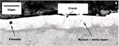
The surface layer which is also known as The Recast Layer. This layer is at the immediate surface and is generally very hard and brittle. (Remember it has seen a very high temperature, which is up to the point of melting). The objective of the EDM is to vaporize the surface layer and remove it. But it is, in reality a melted layer which will cool rapidly at the surface of the tool. The surface is now in a highly residual and stress full condition which can and very often does, lead to cracking, heat checking and ultimately premature surface failure. More often than not, it is the heat treater who is blamed, no matter how careful the heat treater has treated the tool.
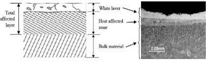
The untempered martensite transformation occurs due to the heat sink that takes place from the generated heat of the EDM. The generated heat energy diffuses into the body of the tool and creates the appropriate transformation from austenite into martensite because of the rate of cooling. This will give rise to a stressful potential crack occurrence condition (due to the untempered, unstable m fresh martensite). Hardness values of the untempered martensite layer can be as high as 62 HRC (depending of course on the chemistry of the steel).

Below the untempered martensite layer will be another layer of what can be a tempered martensite layer with hardness values (once again depending on the steel chemistry) in the region of up to 52 to 54HRC.
Below that layer on tempered martensite will be the original hardness and microstructure of the base material.
The recast layer is the dangerous layer, because not all of the melted layer has been flushed away. When a failed/cracked sample is etched, the recast layer will be seen as a white layer (do not confuse with the white layer of a nitrided surface).
What can be done to prevent (or at least reduce the risk of potential cracking)? The only simple procedure (but with no guarantee) that can reduce the risk of cracking, would be to temper the component immediately after the EDM procedure.