In this installment of the Controls Corner, we are addressing load configurations in a furnace. An industrial furnace is made up of multiple zones for the heating of the load. These zones are strategically placed to minimize heat losses and to give the best heat profile for the application (minimize hot and cold spots in the vessel). In this Technical Tuesday installment, guest columnist Stanley Rutkowski III, senior applications engineer at RoMan Manufacturing, Inc., highlights the differences between power controls based on voltage and current.
This informative piece was first released inHeat Treat Today’sSeptember 2024 People of Heat Treat print edition.
The utility company transmits power to the electrical grid in terms of “voltage” and “current.” Voltage is the pressure to push the current through the wires. The amount of voltage required is a function of the losses in the system (resistance, reactance, and impedance). Utility companies transmit this via the highest voltage available to minimize the current. By minimizing the current, the cross section of the conductors to transmit gets smaller and less costly to run over long distances. At an industrial facility, a step down transformer (distribution type) is used to change the high voltage from the utility company to plant voltage (and by the same ratio increase the current from low to high).
In the operations of a furnace, the term commonly used is power, which is a multiplication of two variables, voltage and current.
In the operations of a furnace, the term commonly used is power, which is a multiplication of two variables, voltage and current. The utility company transmits power in a three-phase configuration with 120 degrees difference between phases (typically labeled A-B, B-C, and C-A). Let’s take a brief look at four major load configurations.
Single-Phase Load
A single-phase load uses one of the three legs of the system in operation. This type of system is best used in three zone applications to try to balance the power of each zone to the utility. A single-phase load allows for the most control of a zone in a furnace as it is individually controlled, but potentially causes the most disturbances to the utility company.
Two-Phase Load (Scott-T)
A Scott-T system is a way to balance load a three-phase system but allow for two loads in operation. In a five zone furnace, you could configure a three-phase system for the middle three zones and a Scott-T system for the first and last zones (front and back). A Scott-T system has a single point of control for the two zones to have the least disturbances to the utility company.
Three-Phase Load
A three-phase load can be in different configurations, the most common being Delta and Wye. The differences between them are the vectors of the voltage and current. A Wye system has less voltage and more current while a Delta system has less current and higher voltage. Care needs to be taken to minimize potential circulating currents that can be created by the vectors of three-phase systems. The three-phase system is a single point of control for the loads and causes less disturbances to the utility company. Mixing of three-phase systems inside a furnace (Delta and Wye) can help further minimize disturbances to the utility company.
IGBT (Insulated-Gate Bipolar Transistor)
An IGBT (Insulated-Gate Bipolar Transistor) system is a hybrid system that uses a three-phase primary to create a single-phase load. This allows for the highest level of control while minimizing the disturbances to the utility company. This system also allows the usage of higher frequencies to shrink the footprint of the transformers, allowing the use of rectification to minimize inductance and minimize the high current runs to the load(s).
About the Author:
Stanley F. Rutkowski III Senior Applications Engineer RoMan Manufacturing, Inc.
Stanley F. Rutkowski III is the senior applications engineer at RoMan Manufacturing, Inc., working on electrical energy savings in resistance heating applications. Stanley has worked at the company for 33 years with experience in welding, glass and furnace industries from R&D, design, and application standpoints. For more than 15 years, his focus has been on energy savings applications in industrial heating applications.
Like most power systems, power control dates back to vacuum tube technology. Like radios, amplifiers, and other industrial equipment, the furnace market started using transistors as the technology evolved. Vacuum tubes were not generally balanced and contained poisonous elements and were phased out of usage in almost all industries. In this Technical Tuesday installment, guest columnist Stanley Rutkowski III, senior applications engineer at RoMan Manufacturing, Inc., distinguishes the different methods used to regulate power input to furnaces.
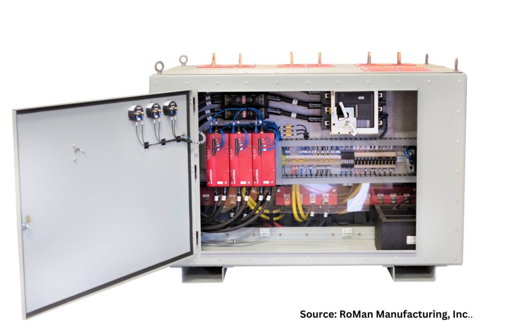
An ERT/SCR power control Source: RoMan Manufacturing, Inc.
In today’s furnace market, there are generally three primary types of control systems: VRT, SCR, and IGBT. Each of these control technologies employs different methods to regulate the power input to the furnace, which in turn generates the required heat. These control systems transfer the power from the plant power system to a transformer in line with the load (heating elements). Power is delivered to a plant in a three-phase system from the utility company. The least costly and highest power factor systems have a balanced load across the three phases during the operation of any furnace.
VRT (Variable Reactance Transformer)
A VRT incorporates a feedback mechanism to either increase or decrease the amount of DC injected into the controlling reactor in the system. This increases or decreases the amount of current in the system to control the heat in the furnace by comparing it to the scheduled setpoint. A VRT system can have the following configurations:
Single-phase power controller for single load applications
Scott-T three-phase power controller (this is a system that allows all three phases of the incoming power system to be utilized in a two-phase load application)
Three-phase power controller (in either a Delta or Wye configuration) for three zone load applications
SCR (Silicon Controlled Rectifier)
An SCR control system uses a pair of thyristors (gated diodes) to control the amount of power applied to the primary of a transformer. The SCR control delays the start of the waveform, and the control point is reset when the waveform crosses the zero line. An SCR system can have the following configurations:
Single-phase, phase-angle controlled for single load applications
Single-phase, zero-cross controlled for single load applications
Single-phase, on-load, tap-changing controlled (this incorporates multiple pairs of the thyristors together to lessen the losses of the SCR system)
Scott-T three-phase power controlled (this is a system that allows all three phases of the incoming power system to be utilized in a two-phase load application)
Three-phase, phase-angle controlled (in either a Delta or Wye configuration) for three zone load applications
Three-phase, zero-cross controlled (in either a Delta or Wye configuration) for three zone load applications
IGBT (Insulated-Gate Bipolar Transistor)
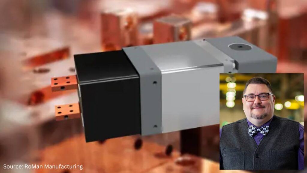
An IGBT power control Source: RoMan Manufacturing, Inc.
An IGBT uses a diode bridge, capacitor, and switching transistors to control the amount of power applied to the primary of a transformer. The input frequency to the transformer is controlled by the switching transistors. The diode bridge is connected to the three-phase system allowing single, Scott-T (two zone), or three zone systems all to pull a balanced load across the three phases of the plant power system. A line reactor is incorporated to maximize the power factor in the system, minimizing the total power usage of the furnace. The IGBT system also uses a square wave into the transformer and a rectifier after the transformer to remove inductance out of the power delivery system to reduce costs of cables, breakers, and other components in the total package.
About the Author:
Stanley F. Rutkowski III Senior Applications Engineer RoMan Manufacturing, Inc.
Stanley F. Rutkowski III is the senior applications engineer at RoMan Manufacturing, Inc., working on electrical energy savings in resistance heating applications. Stanley has worked at the company for 33 years with experience in welding, glass and furnace industries from R&D, design, and application standpoints. For more than 15 years, his focus has been on energy savings applications in industrial heating applications.
“Communication is key.” As heat treating equipment and processes evolve, it becomes critical that the accompanying control systems also develop to maintain “communication.” In this Technical Tuesday installment, guest columnist Stanley Rutkowski III, senior applications engineer at RoMan Manufacturing, Inc., discusses how digital control system communications have improved to increase energy efficiency for manufacturers with in-house heat treat operations.
This informative piece was first released inHeat Treat Today’sMay 2024 Sustainability Heat Treat print edition.
Industrial furnace applications that rely on resistive heating will consume large amounts of electrical energy when processing their loads. Utilizing digital controls technologies to maximize this type of heating allows for a cleaner-and thus greener-approach to energy demands.
Typically, heat treat processes have a long duration (hours to days in length), and each load can have its own unique recipe in the amount of power required. With unique recipes, there tends to be a ramp-up phase (getting the vessel to temperature), followed by a soak phase (which demands more control over the power system), and then a cool-down phase (an even more controlled state). As the power is controlled through the furnace system, disturbances occur with different technologies. This starts with “tube technology,” then variable reactance transformer (VRT) technology, then silicon controlled rectifier (SCR) technology, and finally IGBT (insulated-gate bipolar transistor) technology. As these technologies have evolved, their ability to communicate information digitally has allowed for less disturbance in the power system and allowing both a less expensive energy bill and a cleaner energy usage for the process.
Definitions
Electrical Power
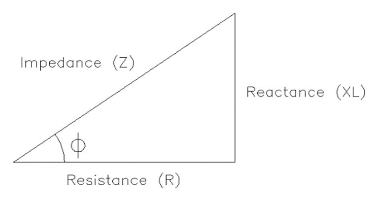
Power losses in an electrical system are defined by five aspects (Figure 1):
Resistance (R): a function of the material cross section and the length of an electrical conductor.
Reactance (XL): a function of the area in a circuit and is a vector 90 degrees offset from resistance.
Capacitance (XC): a vector 180 degrees offset from reactance. In inductive circuits, capacitance can be added for power factor correction.
Impedance (Z): the vector sum of resistance, reactance, and capacitance.
Power Factor [cos(F)]: the ratio of resistance to impedance. In industrial applications, displacement power factor (DPF), the offset of the current to voltage waveforms, is used in the billing of electrical power.
There are five unique aspects that define electrical power usage (Figure 2):
Real power (kW): the amount of power that is generated.
Reactive power (kVAR): the amount of power that is wasted.
Total power (kVA): the rate at which power is consumed. This is also referred to as apparent power.
Power factor (cos(F)): the ratio of real power to total power. In industrial applications, the displacement power factor (DPF) is the offset of the current to voltage waveforms and is used to bill for electrical power.
Peak demand: the capacity required when the power grid experiences the highest power demand in a specified period of time.
3 Most Popular Types of Control Systems
For the most part, today’s furnace manufacturers use three main types of control systems: VRT, SCR, and IGBT. Each operates with slightly different methods to control how power goes into the heat treat furnace and creates heat.
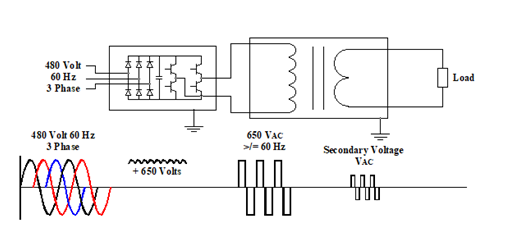
VRT Control System
One traditional resistance heating setup uses a VRT control system that incorporates a saturable reactor, which controls the power applied to the transformer in the system (Figure 3). The control transformer on the output side of the transformer feeds back to the reactor to set the limit on the input power to the transformer.
Figure 3. VRT Control and Transformer Schematic (CT=control transformer); Source: RoMan Manufacturing, Inc.
SCR Control System
Figure 4. SCR Control and Transformer Schematic; Source: RoMan Manufacturing, Inc.
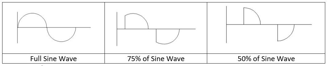
Another traditional resistance heating setup uses an SCR control system that includes dual thyristors (gated diodes) to control the amount of power applied to the primary of a transformer.
The SCR control delays the start of the waveform, and the control point is reset when the waveform crosses the zero line.
Figure 5. Comparison of Sine Waves; Source: RoMan Manufacturing, Inc.
IGBT Control System
Finally, an IGBT control system uses a diode bridge, capacitor, and switching transistors to control the amount of power applied to the primary (i.e., main power input of a transformer). The input frequency to the transformer is controlled by the switching transistors. Since the IGBT control system utilizes all three phases of the power system, the IGBT control can be set to a particular phase for the zero cross (for phase orientation in the application, synchronous mode) or left floating (non-synchronous mode), as is demonstrated in Figure 6. The input voltage to the transformer is increased by the operation of the IGBT control. As such, potential energy savings may be had with these types of controls as compared to tradition controls (such as on-off contractors, time proportioning controls, or other types of current proportioning control systems).
Figure 6. IGBT Control and Transformer Schematic; Source: RoMan Manufacturing, Inc.
Synchronization with the IGBT can be to the incoming lines (A, B, or C phase) and can be offset from each of the phases. The ability to offset from a phase allows for traditional arrangements (Single Phase, Scott-T, Delta and Wye) as well as unique offsets allowing for additional vector heating in the application with AC outputs. The unique arrangements beyond the traditional systems could allow for more uniform heating of the part and less energy being consumed during the process.
Advantages of Utilizing Communications
As technology for controlling heating systems has evolved, and with an emphasis on clean energy sources, the ability to communicate with the control system has increased as well. This communication allows for more precise control of the run for the load, improved power usage (better power factors and less peak power usage as well as less total power usage), and inputs into a preventive maintenance program.
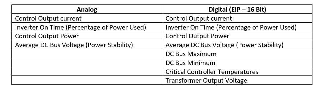
Table A. Analog vs. Digital IGBT Systems
With an IGBT system, both analogue and digital control communications are available today. See Table A for a comparison on how each control option works.
In addition to the EIP defined pieces, there is the ability to access the FPGA system for graphical outputs that can be downloaded into another system in your process for storage, comparisons, or general record keeping for a part run. The FPGA is an internal processor in the control that allows for more data, charting, and diagnostics to be captured and used by the system for both energy consumption and possible preventative maintenance purposes.
Why does this matter? Let’s turn to some possible ways of using the data generated from digital controls systems:
Evaluate average, minimum, and maximum DC bus voltages to plan for the best time and day to run heat treat jobs. For high power draw jobs, planning ahead can minimize power costs; similarly, knowing power trends can be helpful to plan jobs requiring sensitive control of the heating.
Evaluate transformer output voltage to allow the system to detect any shorts in the process. If the controller output and transformer output diverge from the known turns ratio, a change has occurred in the system. This could be corroborated if controller on time and output power do not trend.
Track furnace run records with EIP communications and FPGA data. This will be most helpful in processing lots of data, as is the case for Milspec records.
Evaluate changes in power factor to monitor any loose cables, and so avoid reactive power losses.
Evaluate the current versus the voltage to monitor the resistance of the system. If there is an increase in the resistance, you could project the trends in wear of the heating elements, therefore predicting future required maintenance.
Evaluate the critical control temperatures of the system to know if it is being run close to, or above, its ratings or if there is a disturbance in the cooling systems.
Use knowledge of power usages and power stability to update recipes for load runs so they use less power over the total run; this allows for a less costly power-savings solution. With less power usage, more output of the total facility can be had as each station contributes less to energy consumption
Even more benefits can be realized when users and builders of furnace systems and component manufacturers collaborate in the design of the total system. Such dialogues lead to the creation of more interactive and intuitive solutions that minimize power consumption, minimize downtime, and maximize outputs. These practical benefits are the foundation of a greener system.
About the Author:
Stanley F. Rutkowski III Senior Applications Engineer RoMan Manufacturing, Inc.
Stanley F. Rutkowski III is the senior applications engineer at RoMan Manufacturing, Inc., working on electrical energy savings in resistance heating applications. Stanley has worked at the company for 33 years with experience in welding, glass and furnace industries from R&D, design, and application standpoints. For more than 15 years, his focus has been on energy savings applications in industrial heating applications.