As heat treating facilities strive for energy efficiency and reliability, investing in power improvements can move a company toward sustainable operations. In this Controls Cornerinstallment, Brian K. Turner of RoMan Manufacturing, Inc. compares real power factor and displacement power factor in the efficiency and electrical performance of vacuum furnaces.
In the context of vacuum furnaces, real power factor and displacement power factor are key concepts related to the efficiency and electrical performance of the furnace’s power supply and load. Here’s a comparison:
1. Real Power Factor (PF)
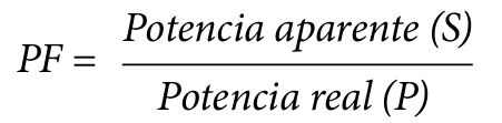
Definition: Real power factor is the ratio of real power (active power, P, measured in watts) to apparent power (S, measured in volt-amperes). It considers both the phase displacement and harmonic distortion.
Relevance to Vacuum Furnaces:
Vacuum furnaces, especially those using induction heating, often generate nonlinear loads due to the operation of power electronics.
Nonlinear loads introduce harmonics, which distort the current waveform, reducing the real power factor.
A low real power factor indicates inefficiency, as the system draws more apparent power for a given amount of real power.
2. Displacement Power Factor (DPF)
Definition: Displacement power factor is the cosine of the angle (ϕ) between the fundamental components of voltage and current waveforms. It ignores harmonic distortion and considers only the phase displacement caused by inductive or capacitive loads.
Relevance to Vacuum Furnaces
In vacuum furnaces, the inductive nature of components (e.g., transformers and inductive loads) causes a lagging power factor, which is reflected in the DPF.
A poor displacement power factor (e.g., heavily lagging) means the system has significant reactive power demands, affecting the sizing of transformers and power distribution equipment.
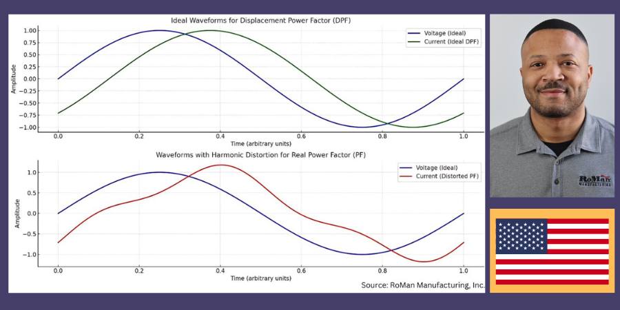
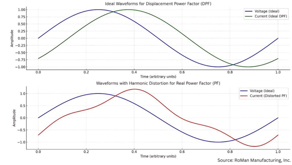
The above waveforms illustrate the difference between displacement power factor (DPF) and real power factor (PF) as they relate to current and voltage:
Top Chart: DPF — Ideal Conditions
The green sinusoidal waveform represents the current in an ideal displacement power factor scenario, where only phase displacement (ϕ) exists between the voltage (blue curve) and current.
The waveforms are clean and sinusoidal, indicating no harmonic distortion.
Bottom Chart: PF — With Harmonic Distortion
The red waveform represents the current with added harmonic distortion, typical in systems with nonlinear loads, like vacuum furnaces.
This distortion causes the real power factor to drop compared to the displacement power factor, even if the fundamental phase relationship is the same.
Waveforms that illustrate DPF vs. PF as it relates to voltage and current
Effects on Transformer and Utility Transformer Sizing
Increased Apparent Power Demand
A lower real power factor (due to harmonics) means the transformer must handle higher apparent power (S), even if the real power (P) is unchanged.
This can necessitate larger transformers, increasing capital costs.
Thermal Stress
Harmonics lead to additional losses (eddy currents and hysteresis), causing transformers to overheat and reducing their efficiency and lifespan.
Voltage Regulation Issues
Harmonics distort the voltage waveform, which can affect sensitive equipment and require transformers with tighter voltage regulation capabilities.
Utility Penalties
Utilities often impose penalties for low real power factor, incentivizing users to improve power quality through harmonic filters or power factor correction.
Conclusion
Addressing power factor in vacuum furnaces is crucial for improving efficiency and reducing operational costs. As heat treating facilities strive for energy efficiency and reliability, investing in these improvements is a step toward sustainable operations.
About the Author:
Brian Turner Sales Applications Engineer RoMan Manufacturing, Inc.
Brian K. Turner has been with RoMan Manufacturing, Inc., for more than 12 years. Most of that time has been spent managing the R&D Lab. In recent years, he has taken on the role as applications engineer, working with customers and their applications.
For more information: Contact Brian at bturner@romanmfg.com.
As heat treating facilities strive for energy efficiency and reliability, investing in power improvements can move a company toward sustainable operations. In this Controls Cornerinstallment, Brian K. Turner of RoMan Manufacturing, Inc. compares real power factor and displacement power factor in the efficiency and electrical performance of vacuum furnaces.
En el contexto de los hornos de vacío, el factor de potencia real y el factor de potencia de desplazamiento son conceptos claves en relación a la eficiencia y el comportamiento tanto de la fuente de energía eléctrica como de la carga del horno. A continuación, una comparación entre los dos factores.
1. El factor de potencia real (PF, por sus siglas en inglés)
Definición: El factor de potencia real es la relación entre la potencia real (potencia activa, P, medida en vatios) y la potencia aparente (S, medida en voltamperios). Da cuenta tanto del desplazamiento de fase como de la distorsión armónica.
Relevancia para hornos de vacío:
Los hornos de vacío, en particular los que funcionan con calentamiento por inducción, con frecuencia generan cargas no lineales debido a la operación de la electrónica de potencia.
Las cargas no lineales conllevan armónicos que distorsionan la forma de onda de la corriente generando una disminución en el factor de potencia real.
Un bajo factor de potencia real es indicador de ineficiencia ya que el sistema se ve obligado a aumentar el consumo de potencia aparente para generar la potencia real que se requiere.
2. El factor de potencia de desplazamiento (DPF, por sus siglas en inglés)
Definición: El factor de potencia de desplazamiento es el coseno del ángulo (ϕ) entre dos componentes fundamentales: el voltaje y las formas de onda de la corriente.
Relevancia para hornos de vacío
En los hornos de vacío la esencia inductiva de los componentes (p.ej., los transformadores y las cargas inductivas) genera un factor de potencia de retardo que se ve reflejado en el DPF.
Un bajo factor de potencia de desplazamiento (es decir, con retardo importante) implica demandas significativas para el sistema en cuanto a potencia reactiva, lo que a su vez afecta el tamaño de los transformadores y del equipo de distribución de energía.
Tabla superior: DPF – Condiciones ideales
La forma de onda sinusoidal verde representa la corriente en un escenario con factor de desplazamiento de potencia ideal en el que interviene únicamente el desplazamiento de fase (ϕ) entre el voltaje (curva azul) y la corriente.
Las formas de onda se ven limpias y sinusoidales, indicando la ausencia de distorsión armónica.
Tabla inferior: PF — Con distorsión armónica
La forma de onda roja representa la corriente con la intervención de la distorsión armónica, situación típica de sistemas con cargas no lineales, caso de los hornos de vacío.
Esta distorsión genera una disminución en el factor de potencia real frente al factor de potencia de desplazamiento, aún cuando no se haya modificado la relación en la fase fundamental.
Formas de onda que permiten visualizar el DPF vs. el PF en relación a voltaje y corriente
Efecto sobre el tamaño de transformadores y transformadores de distribución
Aumento en la demanda de potencia aparente
Un factor de potencia real disminuido (debido a los armónicos) implica que el transformador deberá manejar una mayor potencia aparente (S) sin importar que la potencia real (P) no haya cambiado. Esto puede aumentar los costos de capital al requerir transformadores más grandes.
Estrés térmico
Los armónicos llevan a pérdidas adicionales (por las corrientes inducidas y la histéresis) generando el sobrecalentamiento de los transformadores y disminuyendo la eficiencia y duración de los mismos.
Regulación de voltaje
Los armónicos distorsionan la forma de onda del voltaje, lo que podría afectar los equipos sensibles y obligar al uso de transformadores capaces de regular de manera más precisa el voltaje.
Penalización por consumo energético
Los proveedores del servicio de energía muchas veces aplican sanciones por un bajo factor de potencia real, con lo que buscan incentivar a los usuarios a mejorar la calidad de la potencia mediante el uso de filtros armónicos o corrección del factor de potencia.
Conclusión
La revisión del factor de potencia en los hornos de vacío es de crítica importancia para lograr una mayor eficiencia y la reducción de los costos operativos. En su avance hacia la eficiencia y la fiabilidad energética, invertir en estas mejoras permitirá a las plantas de tratamiento térmico acercarse un paso más a la operatividad sostenible.
Traducido por: Shawna Blair
About the Author:
Brian Turner Sales Applications Engineer RoMan Manufacturing, Inc.
Brian K. Turner has been with RoMan Manufacturing, Inc., for more than 12 years. Most of that time has been spent managing the R&D Lab. In recent years, he has taken on the role as applications engineer, working with customers and their applications.
Processes that utilize electric-powered industrial heaters instead of fossil fuels will necessitate improved power consumption management. Therefore, advanced technologies in power management systems are critical, as in-house operations think about cost savings and electric power requirement compliance.
Janelle Coponen, senior product marketing program strategist, and Christian Schaffarra, director of research and development — Power Control Solutions’ Engineering Team, both of Advanced Energy, address the key to the discussion, SCRs and VSC, in this Technical Tuesday.Read more to understand how the reduction of harmonics allows operations to better manage energy consumption.
This informative piece was first released inHeat Treat Today’sJanuary 2025 Technologies To Watch in Heat Treating print edition.
Processes are increasingly converting to electric-powered industrial heaters instead of fossil fuels to improve process control and comply with the latest energy policies. This transition enables greater operational efficiencies but necessitates improved power consumption management by companies and their heat treat operations.
The integration of advanced technologies in power management systems is critical for both cost savings and to comply with electric power requirements. Among these technologies, silicon-controlled rectifiers (SCRs) and voltage sequence control (VSC) play a pivotal role in optimizing energy consumption. This article explores the significance of the reduction of harmonics by using a special energy-efficient mode to allow facilities to better manage and reduce their energy consumption.
What Are SCR Power Controllers?
Figure 1. SCR power controller
SCR power controllers regulate the power delivered to resistive or inductive loads. Unlike traditional mechanical switches, SCRs offer faster switching times and greater reliability. They are commonly used in applications requiring heating, melting, or bending such as heating elements, motors, and lighting systems.
These devices control electrical power, current, or voltage with high precision and reproducibility. They adjust the phase angle of the AC supply, allowing for finer control over the amount of power sent to the load. This reduces energy consumption and minimizes wear on the equipment, thereby extending its lifespan. Phase-angle firing is designed for high dynamic loads with small thermal inertia and allows for high control dynamic, soft and bump-less loading, and exact current-limit setting.
SCR power controllers produce high manufacturing quality and efficiency through:
Energy efficiency of approximately 99.6%
Power density of approx. 18 W/in3 (for 3-step VSC SCR)
High accuracy up to 1% for output power, 0.5% output voltage
Flexibility
EtherCAT Interface
Traditional SCR operation can be inefficient, especially under partial loads. An energy-efficient mode optimizes the SCR firing angle based on load requirements, reducing energy waste. By adapting to varying loads, these controllers improve system efficiency, lower energy costs, and reduce environmental impact.
Figure 2. Phas-angle firing control mode
Understanding Power Factor
Power factor (PF) is a critical component, representing the ratio of real load power (kW, the actual power consumed) to apparent load power (kVA, the total power supplied). It is a measure of how effectively electrical power is being converted into useful work output. A power factor of 1 (or 100%) indicates maximum efficiency, while lower values indicate wasted energy due to reactive power.
In many industrial settings, a low power factor can lead to higher electricity bills and additional charges from utility companies. Utilities must generate more power to compensate for the inefficiencies caused by reactive power, which does not perform useful work.
Benefits of Improved Power Factor and Reduced Harmonics
One significant advantage of using SCR power controllers is the ability to minimize harmonic distortion. Harmonics are voltage or current waveforms that deviate from the ideal sinusoidal wave, often caused by non-linear loads like electronic devices. These distortions can lead to overheating, equipment damage, and inefficiencies within the electrical system.
Figure 3. Power triangle
Reducing harmonics improves the overall efficiency of power systems and smoother equipment operation, which can prevent costly downtime. Additionally, improving power factor can result in financial savings by reducing energy loss, lowering demand charges, and increasing the capacity of existing electrical infrastructure.
This results in lower energy bills, less wasted energy, and better system reliability. Improved power factor can also help meet regulatory standards requiring specific power factor levels.
Special Energy-Efficient Mode, Voltage Sequence Control (VSC)
VSC complements SCR technology to enhance power system performance by managing voltage levels more effectively. It systematically sequences voltage application to loads, which improves power quality and extends the lifespan of equipment.
VSC is particularly beneficial for applications with inductive loads, where voltage management can significantly reduce inrush currents and mitigate harmonics. By integrating VSC with SCR technology, industries can harness the benefits of both systems, ensuring a stable and efficient power supply.
Combined Advantages of SCRs with Voltage Sequence Control
Improved energy efficiency: By optimizing firing angles and managing voltage sequences, facilities can achieve substantial reductions in energy consumption.
Cost savings: Lower energy usage translates directly into reduced operational costs, making these technologies economically attractive for businesses.
Enhanced equipment longevity: By reducing stress on electrical components through better voltage management, both SCRs and VSC can prolong the operational lifespan of machinery.
Environmental impact: Energy-efficient systems contribute to lower greenhouse gas emissions, aligning with global sustainability goals and regulatory standards.
Figure 4. Comparison phase-angle firing versus VSC
Advantages and Disadvantages of Using SCR in Voltage Sequence Control Mode
Here are several of the advantages:
Improved stability: Helps maintain voltage stability across the system, reducing the risk of voltage fluctuations and outages.
Enhanced performance: Optimizes the performance of electrical equipment by ensuring they operate within their rated voltage range, improving efficiency.
Protection against voltage imbalances: Monitors and adjusts for voltage imbalances in three-phase systems, which can prevent equipment damage and reduce wear.
Energy efficiency: By maintaining optimal voltage levels, VSC can lead to energy savings and lower operational costs.
Automated control: Often incorporates automation, allowing for real-time adjustments without manual intervention, thus improving response times.
Lowest level of harmonics: VSCs can help minimize harmonic distortion in electrical systems.
Lowest level of reactive power: The specific control design of the VSC can significantly impact the minimum achievable reactive power level, even in a weak grid.
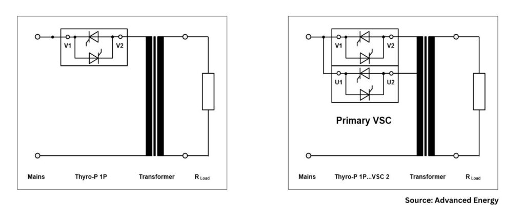
Figure 5a. Standard circuit VAR (phase angle) / Figure 5b. VSC circuit
Compare with a few disadvantages:
Large footprint: Larger power controller footprint versus standard SCR power control system.
Initial cost: The initial investment in VSC systems and related technology can be higher, but payback time is less than a year.
Conclusion
Figure 6. Power factor over outpower in VAR (phase angle) blue line vs. VSC red line
In-house heat treat operations aiming for greater efficiency and cost reduction can benefit from VSC, the energy-efficient mode for SCR power controllers. By enhancing power factor and reducing harmonics, these devices optimize energy use and support sustainable, cost-effective operations. Adopting such technologies leads to significant improvements in industrial power consumption and enhanced savings for end users.
About the Author:
Janelle Coponen Senior Product Marketing Program Strategist Advanced Energy
With more than 21 years of experience in the industrial and energy sectors, Janelle Coponen bridges the gap between technical solutions and market needs. At Advanced Energy, she works alongside engineering teams to translate complex technologies into market ready strategies ensuring alignment between engineering innovations and business objectives.
Christian Schaffarra Director of Research and Development Power Control Solutions’ Engineering Team Advanced Energy
With more than 30 years of experience, Christian Schaffarra leads a research team dedicated to developing and advancing innovative power control technologies, ensuring optimal performance and reliability. He has a deep understanding of both the technical and marketing requirements that drive successful product development and engineered solutions.