Let’s discover new tricks and old tips on how to best heat treat, whatever your application.
In this Technical Tuesday, originally published in the March/April 2024 Aerospace Heat Treatprint edition, Heat Treat Today compiled top tips from experts around the industry to get the best results in your heat treat furnace by optimizing fixtures and fabrications.
#1 Welding Fabrications with Nickel Alloy
Contact us with your Reader Feedback!
“Heat resistant alloys used for heat treating fixtures, muffles, retorts, radiant tubes, and other parts are typically stainless steel or nickel-based austenitic alloys.
“Good welding practices for nickel alloys are centered on the need to remove heat as quickly as possible in order to minimize the time spent in the hot tearing range. The first consideration is to keep the heat input as low as possible to still get a full penetration weld. The actual input in kJ is dependent on the alloy being welded.”
Source: “Marc Glasser on the Tools and Trade Secrets of Heat Resistant Alloy Welding,” reprinted in Heat Treat Today, 2020.
#hottearingrange #austeniticalloys
#2 Consider Corrugated Inner Covers
Inner covers are a component of the batch annealing process in the steel industry. If your inner covers are vertically corrugated, consider horizontally corrugated inner covers instead. Horizontally corrugated inner covers are repairable and, for this reason, offer longer overall life and better value.
Source: Alloy Fabrications
#batchannealing #innercovers #maintenance
#3 Countermeasure To Combat CFC Failure
“It is important to consider the specific process conditions in advance so that unwanted reactions — from carburization to catastrophic melting of the workpieces — can be avoided. Effective countermeasures can be taken.”
Dr. Demmel gives the following countermeasures:
Ceramic oxide coatings such as aluminum oxide (Al2O3) or zirconium oxide (ZrO2) layers placed onto the CFC
Hybrid CFC fixtures having ceramics in key areas to avoid direct contact with metal workpieces
Alumina composite sheets
Boron nitride sprays
Special fixtures made of oxide ceramics
Source: Dr. Jorg Demmel, “CFC Fixture Advantages and Challenges, Part 2,” Aerospace Heat Treating (Heat Treat Today, March 2023).
#CFC #fixtures
#4 Allow for Thermal Expansion
When bringing furnaces to operating temperature, always be aware of thermal expansion of your alloy components. Muffles, retorts, and radiant tubes all expand with heat input. These components must be free to expand within the furnace or early failure may result.
Source: Alloy Fabrications
#thermalexpansion #heattreatfailure
#5 Batch Rotary Retorts — Stay Put and Stay Clean
Batch rotary retorts are positioned on furnace rollers at the front of the furnace. In time, these retorts expand until they no longer track on the rollers. Extend the life of your batch rotary retorts by using adjustable roller brackets (available from Alloy Engineering). And to keep the outlet tubes clean, use Alloy Engineering pigtails and augers to self-clean batch rotary retort outlet tubes.
Source: Alloy Fabrications
#thermalexpansion #heattreatfailure
#6 Corrosion at Every Corner
“[All] materials are chemically unstable in some environments and corrosive attacks will occur. It can often be predicted or modeled. . . In the real world, however, it is important to recognize the various forms of corrosion, namely:
What process holds a soft spot in your heart? Tempering or annealing? For Valentine's Day, turn up the heat -- errr heat treatments -- with this look at the differences in tempering and annealing! Heat TreatToday has resources for you to spark some thought and learning on these processes.
Sentiments and strong feelings can certainly be heightened this Valentine's Day. While tempering and annealing may not lend themselves easily to the holiday, we hope you enjoy a bit of a nod to the day in our headings below. Make use of the Reader Feedback button, too, and keep us in the loop with questions and comments on what heat treatment you love.
Problem with Annealing? Get to the Heart of the Issue
An automotive parts manufacturer was running into problems with cracking parts. The variable valve timing plates were returning from heat treatment with this problem. To determine why those parts were cracking after the annealing process, an investigation was launched by metallurgists at Paulo.
The presence of nitrogen combining with the aluminum already present in the particular steel being used was forming aluminum nitrides. What could be done? Read more in the case study article below to find out a workable solution that allowed the annealing to create a crack-free product.
Induction, Rapid Air, Oven and Furnace Tempering: Which One do You Love?
Contact us with your Reader Feedback!
This article gives some perspectives, from experts in the field, on what kinds of tempering are available and for what the processes are used.
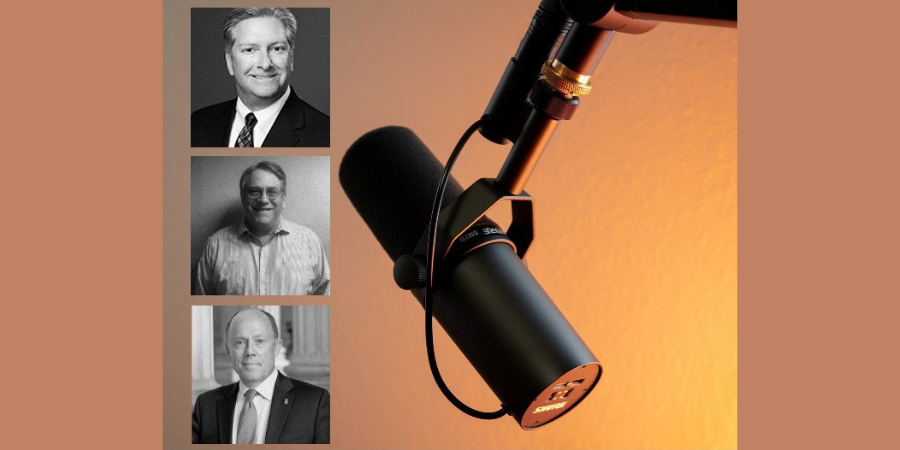
Hear from Bill Stuehr of Induction Tooling, Mike Zaharof of Inductoheat, and Mike Grande of Wisconsin Oven with some basics and background information on tempering. Those reasons alone make this resource helpful with information like this: "tempering at higher temperatures results in lower hardness and increased ductility," says Mike Grande, vice president of sales at Wisconsin Oven. "Tempering at lower temperatures provides a harder steel that is less ductile."
More specific in-depth study is presented as well. The Larson-Miller equation is considered, and the importance of temperature uniformity is emphasized. Read more of the perspectives: "Tempering: 4 Perspectives — Which makes sense for you?"
Cast or Wrought Radiant Tubes in Annealing Furnaces - is Cheaper Really What to Fall For?
Marc Glasser, director of Metallurgical Services at Rolled Alloys, takes a look at radiant tubes. He particularly discusses the cast tubes and wrought tubes. For use in continuous annealing furnaces, there are several factors contributing to choice of radiant tube type.
Marc says, "Justification for the higher cost wrought alloy needs to take into consideration initial fabricated tube cost, actual tube life, AND the lost production of each anticipated downtime cycle as these downtime costs are often much more than material costs." He probes into areas that may not be considered when thinking of all the costs involved. Read more of his article "Radiant Tubes: Exploring Your Options."
Tempering Furnaces: Improvements are Thrilling
The expert behind this piece shows the importance of tempering, particularly in automotive fastener production. Tim Donofrio, vice president of sales at CAN-ENG Furnaces International Limited examines what's working in the tempering furnaces. The products are meeting and exceeding expectations.
To wrap up this Technical Tuesday post on tempering and annealing, head over to this additional resource to round out the scope of each process. "What is the Difference: Tempering VS. Annealing" gives a summary perspective on the heat treatments discussed above.
Find heat treating products and services when you search on Heat Treat Buyers Guide.com
Twice a month, Heat TreatToday publishes an episode of Heat TreatRadio, a unique-to-the-industry podcast. Hear some good news about the future of the energy industry, learn about the benefits of salt quenching, and discover some surprising ways to increase cost to part ratio in this snapshot of three episodes. Enjoy this original content, and happy listening!
Heat Treat Radio: The Greenness and Goodness of Salt Quenching with Bill Disler
Bill Disler President, CEO AFC-Holcroft Source: AFC-Holcroft
What comes to mind when you think of salt quenching? Do the words "green technology" or "environmentally friendly"? Bill Disler, president and CEO of AFC-Holcroft, thinks they should. Quenching is a critical step in most heat treating processes, and, as most heat treaters know, boiling oil on part surfaces and contaminated washers can make quenching a nasty business.
Quenching with sodium nitrate/sodium nitrite salts gets rid of all the "nasties." It is green and it is good, because salt does not boil at temperatures used for quenching, and heat treaters can recycle 99% of quenching salt. No more rinsing oil down the drain.
To learn more about how salt quenching compares to gas quenching, oil quenching, and polymer water quenching, listen to this episode of Heat TreatRadio.
Heat Treat Radio: Energy’s Bright Future with Mark Mills, Senior Fellow at the Manhattan Institute
Mark Mills Senior Fellow Manhattan Institute Source: Manhattan Institute
After the COVID-19 pandemic and the outbreak of the war in the Ukraine, the world is badly in need of some good news. In this episode of Heat TreatRadio, Mark Mills, host of the podcast The Last Optimist and author of the book The Cloud Revolution: How the Convergence of New Technologies Will Unleash the New Economic Boom and A Roaring 2020s, provides some much-needed good news. According to Mark, energy's future is bright. "There is essentially," Mark says, "an infinite supply of energy. Energy is all around us in all kinds of forms. It is always a question of what technologies are available to tap into nature's energy forms[. . .]."
In this optimistic episode, Doug Glenn and Mark Mills discuss how new technologies emerge at just the right time throughout history to solve the energy crisis of the day.
Interested? To hear Mark's thoughts on energy's future, Russia's role in the natural gas industry, and renewables' feasibility in the heat treating industry, listen to this episode of Heat TreatRadio.
Heat Treat Radio: High-Temperature Material Selection with Marc Glasser, Rolled Alloys
Marc Glasser Director of Metallurgical Services Rolled Alloys Source: Rolled Alloys
"Expensive is cheaper." Not convinced? In this episode of Heat TreatRadio, Marc Glasser of Rolled Alloys sits down with Doug Glenn to change the way the heat treat industry thinks about increasing profit per part. Selecting the cheapest part or component does not make economic sense in the long-run. And when it comes to cost savings, the long-run is what really matters.
Glasser asks crucial questions like: Will the weight of a fixture create a heat sink when a lighter (and possibly more expensive) fixture would solve this problem? How many times will the cheaper part need to be replaced compared to the more expensive part? How much will downtime for multiple replacements cost?
To hear the discussion of these questions, as well as practical tips on logging the lifetime of components, listen to this episode of Heat TreatRadio.
Heat TreatToday publisher Doug Glenn and Marc Glasser of Rolled Alloys on why choosing the cheapest material is not always the best way to go. Listen to some of the practical tips Mr. Glasser gives for choosing the right alloy for your application.
Below, you can either listen to the podcast by clicking on the audio play button, or you can read an edited transcript.
The following transcript has been edited for your reading enjoyment.
Doug Glenn (DG): We're going to talk today about something that Marc and I had talked about that kind of caught my attention that I thought might be of interest to our listeners, and that's this whole idea that sometimes buying the cheapest material isn't always the best option. So, that's the topic, but, before we do that, Marc, I want you to tell our listeners and/or viewers a little bit about yourself, your background, and what you're currently doing.
Marc Glasser (MG): I have been a metallurgist or material scientist for forty years. Next month will be exactly forty years since I graduated from Rensselaer Polytechnic Institute with a bachelor's degree in materials engineering. After ten years of working, I went, simultaneously, to a job and to night school for five years and I obtained my Master of Science in material science from, then, Polytechnic University which is now known as the NYU School of Engineering. I've been working in all areas of metallurgy and material science. I've worked in rolling, I've worked in forging, I've worked in powder metallurgy, and I've worked in heat treating laboratories. I'm currently working in metallurgy of heat resistant materials and applications of these alloys in industry.
School of Engineering at NYU
DG: Let's jump in then, Marc. I want to talk to you a little bit about this contention that you and I talked about that sometimes, but not all the time, expensive is better and buying the cheapest isn't always the best. In a nutshell, what are you trying to say on that?
MG: I'll take it even one step further: Expensive is cheaper. Let me expand on that. You have a part and it's a certain price and you know you have a life of two years. . . so that's cost X. You have alloy #2 that's going to cost 60% more. It's going to have a life of eight years. Again, you're going to pay 60% more for this part than you would for the first part of the less expensive alloy. But, over the operating life of that less expensive alloy, you're going to have to replace it three times. You're going to use four separate components. So, 60% of the cost times four, you're spending 240% more than you would spend on one component that's a little more.
It's cheaper up front, but over the entire life cycle of the part, buying four more parts of the cheaper one is a lot more expensive.
DG: Let's talk about some of those hidden factors that come into play when you're analyzing the true cost of selecting those materials. Do you have a couple of examples?
MG: Absolutely. The most stark example, that we made our first case history on, is radiant tubes. For years, the alloy of choice on radiant tubes was a wrought 601 thin wall and you get about two years on it in a typical furnace. Then the casting industry came in and, because of limitations of the machinery, they had to go with a heavier wall that was three times as thick and that cost 30% more, but it got four years of life. Now, there's newer technology and they can cast it a lot thinner, but thinner doesn't last as long. So, for the wrought tube, you're talking about 1/8 of an inch wall thickness. With cast, for the four-year version, is about 3/8 of an inch and if you go down to 1/4 inch or less, you get maybe two or two-and-a-half years and if you go to the more expense wrought alloy, (again, you're talking about 1/8 inch wall), it's 60% more than the original one, 30% more than the cast, and you get eight years out of it.
Now, again, these numbers are based just on the cost of the material. But, you've got to dig a little deeper because you're not capturing the true savings of using the more expensive material because, think of this: If you've been in a heat treating shop and you know your carburizing furnaces, you have to turn it off, cool it down, let it air out because you've got a carbonaceous gas in there and any residual carbon monoxide, if you go in there, you're going to asphyxiate.
The bottom line is, the turnaround can take up to a week. Each time you have to go down for a week, what everybody doesn't even think about is how much revenue in sales and/or in profits are you losing from that week down? And, if you're going from cast to the better wrought alloy, you're talking about one week. If you're still going with the original less alloyed, thinner wrought tube, that's three times. Those savings can be much larger, depending on the facility, than just the material cost; it's just a few thousand dollars. I don't know how to evaluate how many tens of thousands or hundreds of thousands of dollars of lost production would be, but each shop has to consider that. They know the numbers; those are proprietary numbers that need to be considered.
With muffles, it's the same kind of analysis because you have the same alloys except muffles are not typically cast. But, let me give you an example. A lot of muffles operate at 2125 and, again, you use a 601 muffle. They're going to stay perfectly straight and flat at that temp for about six months. At that point, the typical shop will start seeing a little bit of roof sag and it will sag more and more and more. But there's plenty of room, so you can get a lot of sag before it starts interfering with the parts being conveyed. So, my general rule from the shops that I've seen, is that it can sag for about three times as long as it stays straight before the sagging is too great and has to be removed. Typically, it's about two years. With the better alloy, again, the case that I've seen was two years without any sagging and that was a higher temperature.
What we've done is we've actually gone to good customers who understand the concept and we work with them on developing case history. They log in when they put it in and the log in when they take it out. They have good records, number one.
Now, I'm talking predicted metal temperature based off the process temperature which could be more or less because it's estimated. But I know that the one that we looked at was at least 2200 on the metal temperature. And this was one of the really crazy ones because it was replacing a cast material of much higher quality cast material and the cast material was dead straight for a year-and-a-half, it would start to just creep a little, but if you're familiar with casting, there's not a lot of ductility in casting when it starts creeping maybe 3 or 4%, you don't have to worry about more creep; it ruptures! Then, the gas starts escaping and that's no good so they take it down. In this case, when you switch from the cast, the best wrought material was actually cheaper and it lasted longer and the particular customer would just change them every two years because they were still in cost savings mode. Based on my experience, I've predicted that they should be able to get at least six years on it. But, they're not willing to take that chance.
DG: The examples that you gave were the radiant tube and the muffles. I assume the same thing would be true, though, in retorts, for baskets or even fixturing systems, and things like that.
MG: Absolutely. I bring those two up because I have more good case histories.
DG: I assume the same would be somewhat true for fans, and things of that sort, if necessary, although you wouldn't be worrying so, so much about sagging and stuff like that. But anything, basically, I assume, metal.
MG: That's correct.
DG: How about measuring the life cycle of materials components? Any tips or tricks you've got for people on how exactly to do that and to get an accurate estimate?
MG: What we've done is we've actually gone to good customers who understand the concept and we work with them on developing case history. They log in when they put it in and the log in when they take it out. They have good records, number one. We've worked with others who've wanted it to work but they didn't do so good of a job tracking it. In one case, it was a much larger furnace where they had many radiant tubes and they were just working with a few of them. Personnel changed – one person didn't let the next person know about the trial and the identity got lost. So, we spent a lot of time for nothing. But, what we learned on that one is something real simple: You take a welder and you weld the alloy name somewhere on the tube and that's not going to wear away. Assuming you choose the right consumable, that weld is not going to go away.
DG: You already gave a couple of examples, but let me ask you this: How about a few concrete examples of where a more expensive material produced an overall more cost effective part? You already kind of gave us those back with the radiant tube, but are there any others that you've got along that line?
MG: The radiant tube is a great example. Muffles and retorts. We've been trying to work with some people on larger heat treating trays, but, again, there the task people have done a pretty good job, so we're trying to find a few people willing to go out on a limb and try something better.
Here, the concept is the idea of something lighter so that we don't look as much about the cost of the component. If you go with a lighter fixture, your furnace has a weight capacity and if you cut your weight 20-30%, you can put more parts on it and have more of your furnace BTUs going to heat treat parts instead of fixturing. When you're putting BTUs into parts, you're talking more profit per part.
DG: Right. You're not spending as much time, basically, using a basket as a heat sink, or something like that.
MG: Exactly. And, that's a concept that I introduced at one of the conferences about a year and a half ago. These things take time to percolate before they're accepted by people.
DG: Speaking of acceptance, let me ask you this question: Are these concepts that we've been talking about, the idea that sometimes less expensive is not better, is it widely accepted, do you think? I mean, do you think people understand it, generally speaking?
MG: Some people do. Not as much as I'd like to see! The other obstacle you're looking at is when you're looking at four years versus eight years and you look at some of the larger companies, you may have personnel turnover and one person doesn't want his 'replacement' to get all the credit. These are things that were learned the hard way. You have to get the right people to try it. A family-owned business is a perfect place.
I can give you another real good example on heat treating baskets where it made a difference. I'm going to give the name because I have done papers with him at a conference on this subject so I don't think it's taboo. I work with Solar Atmospheres on a basket for an extremely high temperature heat treating process that was slightly under 2300 degrees Fahrenheit. (We can say that because it's in the case history.) The first baskets that he used were your traditional Inconel 600 601 and they were supporting heavy parts. After five cycles, they had to cut all the sides off, hand straighten them (each of the sides) and weld it back together. That's timely. So, he went to another alloy, a better alloy, a competitor's alloy (HR120), and got ten cycles on it. He was very happy. Then, one of the people at their headquarters heard me give a talk on this new alloy that we had, our 602CA, which we trademark as RA602CA, and he got excited. He started asking me questions after the presentation and we eventually got kicked out of the room because it went well beyond the break; so we continued out in the hall as we walked to our company's booth and we talked. It took about ten to twelve months before they were ready to try it. We worked with their fabricator to get the material. They were up to forty-five cycles before they straightened it and there's a catch, though, to that. At forty-five cycles, they probably could've continued, but during the pandemic in 2020, when things were slow, they made a smart business decision that this would be a great time to do the straightening. I can't fault them, but it would have been nice to know just how many more. But, at forty-five versus ten, it is probably a similar cost at the time of manufacture. That's a no-brainer.
DG: So, we've covered some of the basics. We understand that it's not necessarily widely accepted so people should pay attention to some of these things that you've said. Are there any other economic factors that you think people aren't necessarily taking into consideration when they're doing material selection, besides the things we've talked about. Initial cost, life cycle, cost of replacement, and those types of things. Is there anything else that they ought to be thinking about?
As I mentioned in one of the cases, when there is significant down time to replace a part, you've got to consider how much money you're not bringing in because you're down for a week, or however long it is. This is often overlooked, as well.
MG: As I mentioned in one of the cases, when there is significant down time to replace a part, you've got to consider how much money you're not bringing in because you're down for a week, or however long it is. This is often overlooked, as well.
DG: To me, that's cost of replacement, because that's not just a hard replacement cost, but the downtime replacement, right?
MG: It's a little less obvious, though.
DG: Those are all good thoughts, Marc. When people go to do material selection, keep some of these things in mind. It's not just a matter of what the buyer, the purchaser guy, sees coming across his desk and comparing those two costs, let's talk about the material properties and longevity of the product and things of that sort.
I know that you, being with Rolled Alloys, you guys help customers, I imagine, pretty much continually on things like this. If people want to get in touch with you or Rolled Alloys, how is it best to do that?
MG: There are a couple of ways. The first way is my email: mglasser@rolledalloys.com. You can always ask me a question. On our website, there is a link to ask a metallurgist a question. I believe, you can also go www.metallurgical-help@rolledalloys.com and that will bring you to one of the metallurgists in my department and somebody will get an answer to you .
DG: Thank you very much, Marc. I appreciate your expertise. We'll hope it's helpful to the heat treat world.
MG: Doug, I thank you for having me as your guest and I look forward to more conversations with you.
Doug Glenn
Publisher Heat TreatToday
To find other Heat Treat Radio episodes, go to www.heattreattoday.com/radio and look in the list of Heat Treat Radio episodes listed.
Heat TreatTodayoffers News Chatter, a feature highlighting representative moves, transactions, and kudos from around the industry.
Equipment Chatter
TAV VACUUM FURNACES SPA sold two horizontal all metal high vacuum heat treatment furnaces to a well-known Chinese heat treater working in the manufacturing industry.
Honeywell announced that Global Control Pte Ltd, a global heating system original equipment manufacturer (OEM), is incorporating Honeywell technologies, including the ControlEdge™ HC900 controller, into its heat treatment solutions to help its customers improve their asset performance, reduce their inventory and lifecycle costs, and save energy.
Grieve Corp. announces 1250°F (667°C) inert atmosphere oven currently used for heat treating firearms components at a customer’s facility.
Tenova, a company specializing in innovative solutions for the metals and mining industries, started up the most productive Electric Arc Furnace in history, a Tenova Consteel® EAF, at Acciaieria Arvedi, Cremona (Italy) on September 17 this year.
ECM Technologies announces the release of a new furnace system which will replace current sealed quench (SQ) or integral quench (IQ) style furnaces.
Hubbard-Hall has completed the first phase of a three-year Digital Initiative Strategy. This phase focuses on creating a more engaging user experience, with use of Web Chat and On-Demand Portal technologies.
Gasbarre Thermal Processing Systems is pleased to announce the recent commissioning of a Vacuum Oil Quench Furnace, which included 2 BAR gas quench capabilities to an international manufacturer.
Kanthal is adding a 60 kW heater to its range of flow heaters to meet demands for higher power in industries like aluminum and glass.
Grieve Corp. Inert Atmosphere Oven
Tenova Consteel® EAF at Acciaieria Arvedi, Cremona (Italy)
ECM Technologies announces new furnace
Gasbarre’s Vacuum Oil Quench Furnace
Personnel Chatter
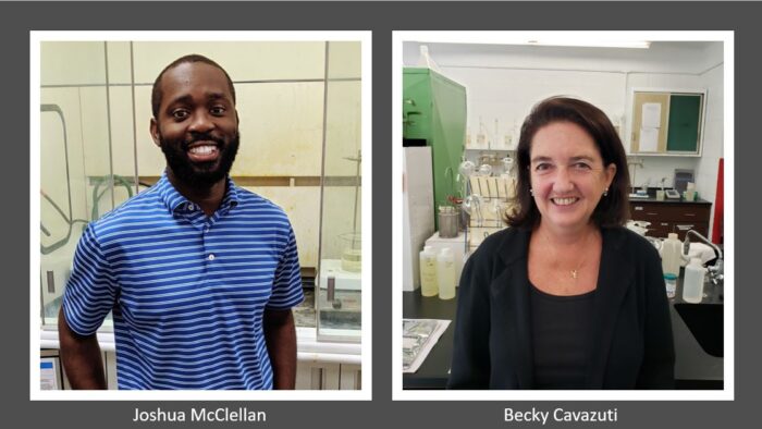
Hubbard-Hall Inc. welcomes Joshua McClellan as application engineer-cleaning and Becky Cavazuti as customer engagement key accounts manager. These roles are critical in expanding Hubbard-Hall’s services in metal finishing operations and achieving customer’s goals with less cost, complexity, and chemical consumption.
Group picture with Joshua and Becky from Hubbard-Hall.
Hubbard-Hall Inc. welcomes Fernando Carminholi as Business Development Manager.
Wire Experts Group, the parent company to Pelican Wire of Naples, Florida and Rubadue Wire of Loveland, Colorado has named Trent Dunn as the new WEG Marketing Manager, with overall responsibility for the marketing departments of all business units, including the parent organization.
The Heat Treating Society of ASM International welcomes to the board Steven Ferdon, director engineering technology, Cummins Incorporated. Chuck Faulkner, commercial development manager-heat treatment, Quaker Houghton, and Marc Glasser, director of metallurgical services, Rolled Alloys, were reappointed for a second three-year term.
Fernando Carminholi Business Development Manager Hubbard-Hall, Inc.
Trent Dunn Wire Experts Group Manager Marketing Manager
Marc Glasser serves at Heat Treating Society of ASM International
Company Chatter
Brian Fitzpatrick, District 1 US Congressman, Bucks County, Pa., at the Solar Manufacturing plant.
Custom Electric Manufacturing was acquired by Sweden-based Kanthal in 2018 and will now go to market under the Kanthal brand. The transition will be effective as of January 1, 2021. View a video with Jon Hartmayer and Victor Strauss about the brand transition.
Brian Fitzpatrick, District 1 US Congressman, Bucks County, PA., toured the Solar Manufacturing plant in Sellersville, PA.
Advanced Heat Treat Corp. (AHT), a recognized leader in heat treat services and metallurgical solutions, announced a new logo for their UltraOx® heat treatment today. The new logo features an ox as the term ‘ox’ is often used as an abbreviation of the term ‘oxide’ – one of the three steps of this protective heat treatment.
Jon Hartmayer Sales Area Manager NAFTA Kanthal
Victor Strauss Vice President and Director of Operations CEM
Kudos Chatter
Lindsey Newcomb, Marketing Manager at Advanced Heat Treat Corp. (AHT), was recently selected for a “2020 20 under 40 list,” furthering the understanding/awareness of heat treat among the general public.
In August, 2020, Solar Atmospheres of Western Pennsylvania (SAWPA) participated in a Boeing Supplier Assessment. The on-site, preventative engagement resulted in zero findings and Solar, once again, achieving preferred status for Heat Treating, Hardness, and Non-Destructive Liquid Penetrant Testing.
Advanced Heat Treat Corp. recognized in the 2020 Courier Employers of Choice. These honorees demonstrate the diversity of career options in and continued commitment to healthy communities in Cedar Valley, IA.
Solar Atmospheres of Western Pennsylvania (SAWPA) recognized from the Boeing Supplier Assessment
Heat TreatToday is pleased to join in the announcements of growth and achievement throughout the industry by highlighting them here on our News Chatter page. Please send any information you feel may be of interest to manufacturers with in-house heat treat departments especially in the aerospace, automotive, medical, and energy sectors to editor@heattreattoday.com.
Heat resistant alloys used for heat treating fixtures, muffles, retorts, radiant tubes, and other parts are typically stainless steel or nickel based austenitic alloys. Welding of these alloys requires practices that are often exactly the opposite of the practices required for carbon and alloys steels since austenitic stainless steels do not undergo phase transformations. Metallurgists are often asked many questions on the proper welding methods. Carbon and alloy steel welding requires practices and procedures that will minimize or prevent the chances of cracking due to potential martensite formation during weld solidification. Austenitic stainless steels do not undergo any phase transformation. They require rapid cooling to prevent solidification cracks due to hot cracking. Thus different procedures are required.
In this Heat Treat TodayTechnical Tuesday feature, Marc Glasser, Director of Metallurgical Services for Rolled Alloys, provides some basic information on the metallurgy as well as good welding practices to follow.
Reprinted with permission from Heat Treat 2019: Proceedings of the 30th Heat Treating Society Conference and Exposition, October 15-17, 2019, Detroit, Michigan, USA. ASM International, 2019.
CHEMISTRY CONSIDERATIONS
Most heat resistant alloys used in the heat treating industry for components are austenitic. They can be austenitic stainless steels, or austenitic nickel alloys. The key word is austenitic. One of the virtues of austenitic materials is that they are not subject of phase changes from cooling to heating or heating to cooling. This is markedly different from alloy and carbon steels, which undergo a phase transformation from austenite to ferrite and cementite. The cooling must be slow enough to prevent martensite formation, so preheating and postheating are performed to either prevent this phase transformation or to temper any formed martensite.
Austenitic alloys do not undergo phase transformations to martensite, and as a result slow cooling the material is the worst operation that an austenitic alloy can be subject to. In austenitic alloys, the main concern is the tendency for welds to hot tear upon solidification[1]. In stainless steels with up to approximately 15% nickel, the solution is simple. The composition is adjusted to form small amounts of ferrite during solidification[2]. Prediction of the ferrite number FN, which represents an estimate of the amount of ferrite in the weld after solidification, is predicted by using Schaeffler diagrams. The ferrite nullifies the effect of certain trace elements that cause hot cracking [1]. One of these trace elements, phosphorous cannot be refined out of the material. Since these materials are all melted from scrap metal, the amount of phosphorous found in the heat will mirror the amount in the scrap. Sulfur, silicion, and boron also contribute to hot shortness, but these elements can be refined to very low levels in the steelmaking process.
For higher nickel bearing grades, with more than 20% nickel, the chemistry precludes the possibility of ferrite formation. Therefore, other means must be employed to prevent hot tearing during solidification. In this case, the residual trace elements, particularly P must be kept low, as they lead to hot shortness [2, 3]. Certain alloy additions including manganese (Mn), niobium (Nb), molybdenum (Mo), and carbon (C) all reduce the propensity of austenitic nickel alloys and high nickel stainless steels to crack [4]. 310 stainless steel stans in a unique position having neither ferrite formers nor weldability-enhancing alloy additions. In this alloy, control of chemistry and residuals is of utmost importance.
The other key to successful welding of nickel alloys is to minimize the time spent in the high temperature range where they are susceptible to hot tearing [4].
GOOD WELDING PRACTICES
Good welding practices for nickel alloys are centered on the need to remove heat as quickly as possible in order to minimize the time spent in the hot tearing range. The first consideration is to keep the heat input as low as possible to still get a full penetration weld. The actual input in kJ is dependent on the alloy being welded.
Heat input (HI) is defined as: HI (KJ/in) = Voltage x Amperage x 6/(Speed (inch/min) x 100)
Welds should NOT be preheated and interpass temperatures should be 200°F maximum. The cooler the interpass temperature is, the less likely hot tearing is [5]. A reliable, easy test for a welder is the spit test. Spit on the weld, and if it boils it is still to hot, and further waiting is in order.
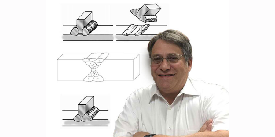
One of the most important considerations in welding nickel alloys is to weld in a straight line along the length of the weld and do not weave. Welders tend to weave from side to side especially when welding nickel alloys which are more viscous that carbon steels and this weaving makes the metal flow better. While this technique works well for carbon steel where a higher heat input and slower cooling are necessary, it is exactly the wrong procedure for nickel alloys. Weaving tends to flatten out a weld. This in turn reduces the crown height and strength.
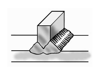
Furthermore, weaving tends to increase the heat going into the weld and slow down the weld speed. The key is to get a nicely shaped, convex weld bead, as illustrated in Figure 1. A concave bead configuration tends to crack along the centerline [5].
Figure 1: Convex vs. Concave Weld
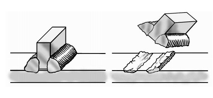
Full penetration welds are important. Beveling one or more of the pieces to be joined may be required to get a full penetration weld. Incomplete penetration leaves a void between the two workpieces. Such a channel can entrap surface treating gases leading to brittle pieces surrounding the weld. Furthermore, the gap can act as a propagation site for cracks which form from thermal cycling from heat treating. This is shown in Figure 2 below.
Figure 2: The effect of non fully penetrated welds
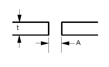
Some suggested joint designs include square butt joint, single V joint, double V joint, single U joint, double U joint, J groove joint, and T Joint. These are shown in Figures 3 to 9 below, along with design criteria. These suggestion grooves are from ASME code[6], but are good guidelines to follow even if code stamps are not required.
Figure 3: Square butt joint. Maximum t = 1/8 ” Gap A = 1/16″ Minimum, 3/32″ Maximum
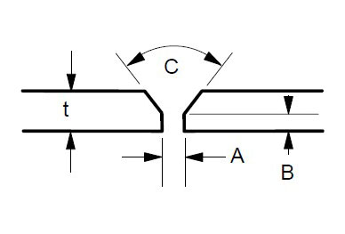
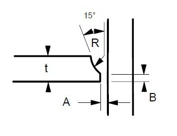
Figure 4: Single V Joint. Maximum t = 1/2″ Gap A = 1/16″ Minimum, 1/8″ Maximum Land B = 1/16 to 3/32″ Angle C = 60 – 75 degrees
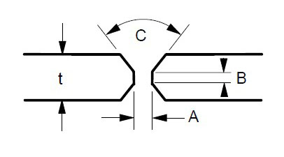
Figure 5: Double V Joint. Gap A = 1/16″ Minimum, 1/8″ Maximum Land B = 1/16 to 3/32″ t = 1/2″ or greater Angle C = 60-75 degrees
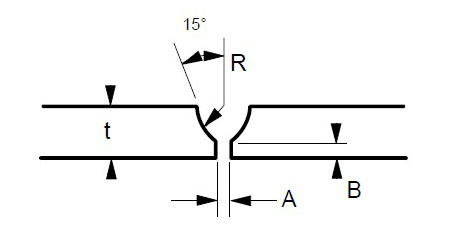
Figure 6: Single U Joint. Gap A = 1/16″ Minimum, 1/8″ Maximum Land B – 1/16 to 3/32″ Radius R – 3/8″ Minimum For single groove welds on heavy plate thicker than 3/4 inch. Reduces the amount of time and filler metal required to complete the weld.
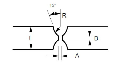
Figure 7: Double U Joint. Gap A = 1/16 to 1/8″ Land B = 1/16 to 3/32″ Radius R = 3/8″ Minimum Minimum t = 3/4″
Figure 8: J Groove Joint. Gap A = 1/16 to 1/8″ Land B = 1/16 to 3/32″ Radius R – 3/8″ Minimum For single groove welds on plates thicker than 3/4 inch. Reduces the amount of time and filler metal required to complete the weld.
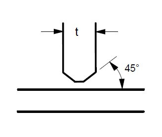
Figure 9: T Joint. t = greater than 1/4″ For joints requiring maximum penetration. Full penetration welds give maximum strength and avoid potential crevices.
Regardless of which joint is selected, the purpose is to obtain a full penetration weld with no voids or channels, as shown in Figure 10 below.
Figure 10: Example of Full Penetration Weld
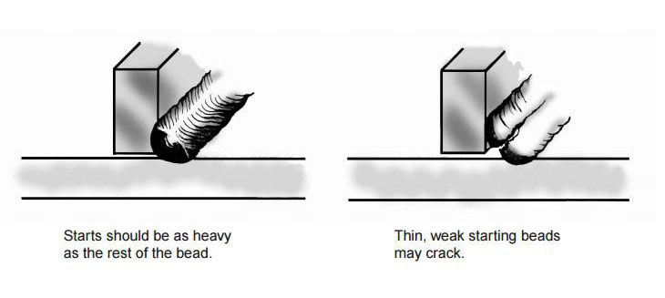
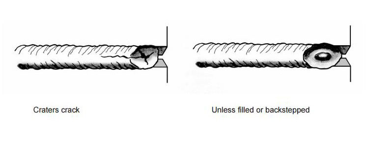
Both the starting and finishing ends of the weld beads can be crack initiation sites. The best practice for starting is to make the start of the weld bead as heavy as the rest of the weld bead [4]. A light or thin start up can cause cracking. This is shown in Figure 11. Furthermore, in nickel alloys, the end of the bead can sometimes yield a star shaped crack. This can be eliminated by backstepping the weld for ½ to 1 inch as shown in Figure 12 [3].
Figure 11: Start welds as heavy as the rest of weld beads
Figure 12: Backstep the weld ends to prevent cracking
Cleanliness is extremely important for welding stainless and nickel alloys. Some general rules include [5]:
Remove all shop dirt, oil, grease, cutting fluids, lubricants, etc. from welding surface and on the area 2 inches wide on each side of the weld joint with suitable cleaning agent.
Eliminate all sources of low melting metal contaminants from paints, markers, dies, back up bars, etc. Chromium plate copper back up bars can form a barrier between copper and the weld surface. Copper can cause HAZ cracking in nickel alloys. These low melting contaminants cause cracking and failures in nickel alloy and stainless steel welds. Avoid using lead or copper hammers in fabrication shops.
Grind clean the surfaces and the HAZ areas. Chromium scales melt at higher temperatures than the base metals and will not be reduced by filler metals.
When welding to nickel alloy or stainless to plain carbon steel, the plain carbon steel must be ground on both sides too.
SHIELDING GASES
Bare wire welding requires a shielding gas to protect the weld from oxidation, loss of some elements to slag or oxide formation, and contamination.
Most stainless steel and nickel alloys require 100% argon for shielding for the GTAW or TIG process.
GMAW or MIG welding has two distinct modes of metal transfer. Spray arc processing transfers metal between wire tip and workpiece as droplets. Short circuit processing transfers the metal in sheets or globules. The most common shielding gas for spray arc GMAW welding is 100% argon. 10-20% helium can be added along with small amounts of carbon dioxide (1% max) to improve bead contour and reduce arc wander [1]. Short circuit GMAW welding uses blends of inert gases usually either 75% argon – 25% helium or 90% helium – 7.5% argon – 2.5% carbon dioxide.
In order to prevent hot cracking with the GMAW process, 602CA® requires a unique blend of 90% argon – 5% helium – 5% nitrogen and a trace (0.05%) carbon dioxide. This blend was trademarked as Linde CRONIGON® Ni30. It is not readily available but there are other close alternate quad gas blends that are commercially available. For GTAW welding, argon with 2.5% nitrogen is used to prevent cracking in 602CA. The nitrogen is the key to preventing cracking in 602CA regardless of method.
RESTRAINT AND DISTORTION CONTROL
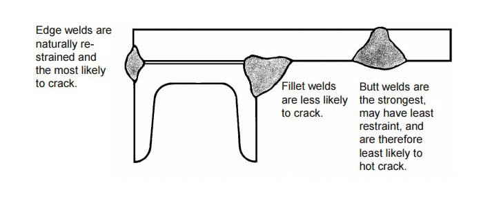
Weld metal shrinks as it freezes. To accommodate the dimensional changes associated with freezing, either the base metal or the weld must move to prevent cracking or tearing. In complex assemblies with multiple welds, each weld, when solidified functions as a stiffener, further restricting movement of subsequent welds. In such cases, the most difficult or crack susceptible weld in the assembly should be made first and the easiest and strongest welds should be made last [5]. An example is shown in Figure 13 below.
Figure 13: Welding with multiple welds. In this example, the edge weld on the left would be the first weld made. The fillet weld in the middle should be the second made, and the butt weld on the right would be the last one made
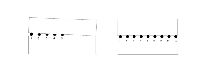
When multiple tack welds must be made, they should be sequenced along the length of the plate [5]. Tack welding from one end to the other that is made in order will result in plate edges closing up as shown in Figure 14.
Figure 14: Tack welding in order along plate edge (left) can close up and distort the joint. Sequencing the tack welds (right) can greatly reduce distortion
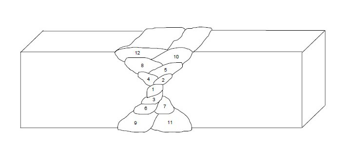
Finally, multipass welds should be sequenced around the center of gravity of the joint as shown in Figure 15 below.
Figure 15: Proper sequencing of multipass welds
REFERENCES
[1] Schaefer, Anton L, Constitution Diagram for Stainless Steel Weld Metal. Metal Progress. ASM, Metals Park, OH. P 680-683. November 1949.
[2] Ogawa T. & Tsunutomi, E. Hot Cracking Susceptibility of Austenitic Stainless Steel. Welding Journal, Welding Research Supplement. P 825-935. March, 1982
[3] Li, L & Messler, R. W. The Effects of Phosphorous and Sulfur on Susceptibility to Weld Hot Cracking in Austenitic Stainless Steels. Welding Journal. Dec. 1999, Vol 78, No. 12.
[4] Kelly J. Heat Resistant Alloys. Art Bookbindery. Winnepeg, Manitoba, Canada. 2013
[5] Kelly J. RA330, Heat Resistant Alloy Fabrication. Rolled Alloys. Temperance, MI. May, 1999
[6] ASME Boiler and Pressure Vessel Code. American Society of Mechanical Engineers. New York, NY. 2013.
This is the second of three articles by metallurgist Marc Glasser on three individual heat resistant alloys. This article will feature RA330®. Please submit your questions about heat-resistant alloys for Marc to editor@heattreattoday.com.
RA330® is a nickel alloy containing 35% nickel, 19% chromium, and 1.2% silicon. Over the years, it has become one of the most widely used wrought heat-resistant alloys due to the combination of its versatility, availability, properties, and cost-effectiveness.
The Chemistry of RA330
The chemistry of RA330 is shown below in Table 1.
There are several important benefits to this alloy including:
Oxidation resistance up to 2100°F
Usable creep resistance up to 1850°F
Utility up to 2100°F when there are no loads applied and some deflection can be tolerated
Resistance to many heat treating atmospheres including carburizing and nitriding
Sufficient nickel content to prevent sigma phase formation and embrittlement
The oxidation resistance of various alloys is shown in Table 2 below¹.
Table 2: Oxidation limits of various materials.
The oxidation limit for RA330 is higher than that of any stainless steel, comparable to alloy 600, and only exceeded by nickel alloys with much higher nickel content.
RA330 Creep Strength
Table 3² shows the creep strength required to produce 1% strain in 10,000 hrs.
The creep strength of RA330 is better than all heat-resistant stainless steel grades except RA 253 MA. It is comparable to alloy 600 but less than the higher nickel alloys 601, RA333, and RA 602 CA. When comparing the economics of RA330 with those of the more expensive nickel alloys, RA330 often has enough creep strength for many heat treating applications and is often the most economical option. There are companies who use RA330 above 1800°F and sometimes as high as the 2100°F oxidation limit. They compensate for the very low creep strength at these temperatures by using braces such as gussets or supports. These supports may be made of ceramic or a different alloy with significantly higher creep strength at this temperature.
Strength Variables and Value
One of the excellent attributes of RA330 is its ability to resist the various atmospheres used in surface or case hardening operations. Thermodynamically, the formation of nickel carbides and nitrides are not favored. With 35% nickel, RA330 has sufficient nickel content to resist carburization, nitriding, and combinations of both. The alloy is not immune to surface hardening, just resistant. The length of resistance time is a function of the process and process variables. For example, field experience shows that 310 muffles used in carburizing atmospheres can completely carburize in as little as 1 month, especially at high temperatures. After that, the material is brittle and can rupture easily. Often, the usable life will be between 1 and 3 months depending on process temperature. A corresponding RA330 muffle under the same atmosphere will last up to 1 year.
Stainless steels are subject to sigma phase formation and embrittlement. Sigma phase is an intermetallic phase that consists of iron and chromium. It precipitates between approximately 1100 and 1600°F. Sigma phase does not embrittle materials at these relatively high temperatures, but at room temperature, sigma phase can reduce charpy impact values to single digits. One sudden impact can cause catastrophic failure. RA330, with 35% nickel, has enough nickel to prevent sigma phase formation.
Applications of RA330
RA330 is available from stock in many product forms. In addition to the traditional plate, sheet, and round bar, RA330 is also available in expanded metal, pipe, and hexagonal nuts. Round bar can quickly be turned into threaded bar. The ability to draw on all these items from stock make RA330 the ideal alloy for maintenance and repair.
RA330 is resistant to thermal fatigue. This property lends RA330 to be the wrought alloy of choice for alloy fixtures and baskets that require quenching a least once a day.
For all of these reasons, RA330 is often an excellent choice for heat treating applications. It has good oxidation resistance, good resistance to case hardening atmospheres, no sigma phase formation, and thermal fatigue resistance. It is available from stock in many forms and sizes. RA330 may not always be the best solution, but often it is the solution that works best.
One of the few atmospheres in which RA330 is not a good choice is sulfur. Like other nickel alloys, the nickel forms a nickel-sulfur intermetallic at a low temperature. In such environments, a lower nickel stainless steel such as 309 or 310 is often a better choice.
RA330® is a trademark of Rolled Alloys.
1. Glasser, Marc, “Selecting an Appropriate Heat-Resistant Alloy,” Industrial Heating. September 2014: 59-65.
2. Condensed from “High-Temperature Environments: Alloy Properties,” https://www.rolledalloys.com/technical-resources/environments/high-temperature/
Marc Glasser is Director of Metallurgical Services at Rolled Alloys and is Heat TreatToday‘s resident expert in process metallurgy, heat treatment, materials of construction, and materials science and testing.
This is the first of three articles by metallurgist Marc Glasser on three individual heat resistant alloys. This article will feature RA 253 MA. Please submit your questions about heat-resistant alloys for Marc to editor@heattreattoday.com.
Alloy 253MA®, marketed in the United States as RA 253 MA®, is a unique stainless steel. It exhibits oxidation resistance to 2000°F. It has shown useful creep resistance in some high-temperature vacuum applications up to 2100°F. Since it is a stainless steel, it is more economical than heat-resistant alloys with higher nickel content. In addition, RA 253 MA exhibits higher creep strength than most heat-resistant alloys with higher nickel content. This alloy is one of the few alloys with measured creep strength up to and above 2000°F.
The Chemistry of RA 253 MA
The chemistry of RA 253 MA is shown in Table 1. The alloy contains additions of silicon and the rare earth metal, cerium, which together create a very adherent oxide up to temperatures between 1950°F and 2000°F. Furthermore, the nitrogen addition enhances the creep strength.
Table 1: RA 253 MA Chemistry
At first glance, RA 253 MA is similar to 309, in terms of chromium and nickel content. However, the silicon and cerium additions enhance the oxidation resistance and the nitrogen boosts the creep strength to more than triple that of 309 and 310 stainless steels at 1800°F. Above 1800°F, 309, 310, RA330, and 600 no longer exhibit usable creep strength, whereas RA 253 MA continues to exhibit usable creep strength up to temperatures of between 2000°F and 2100°F. Table 2 shows the creep properties (1% in 10,000 hours or 0.0001%) of RA 253 MA and other heat resistant materials.
Table 2: Creep Rates for RA 253 MA and Other Heat Resistant Materials
Average Stress, ksi, for 0.0001% per hour Minimum Creep Rate
The Implications in Light of the Performance
In practical terms, the implications of this performance include:
The ability to design parts and fixtures from thinner sections, thus reducing weights significantly, through proper engineering and design.
The ability to design and fabricate fixtures that can hold more weight per furnace load compared to a fixture of the same dimensions with a lesser alloy.
The relatively low nickel content of the alloy, allowing the material to be used successfully in OXIDIZING sulfur atmospheres.
RA 253 MA is best suited for high-temperature structural parts that will see oxidizing, inert, or vacuum environments. Other factors to be cognizant of when considering RA 253 AM include:
The alloy is a stainless steel and therefore subject to sigma phase embrittlement in the temperature range of 1150°F to 1600°F. This means that, over time, the intermetallic sigma phase can form. Sigma phase is quite brittle at room temperature. At operating temperature, the material is still ductile and usable. However, if sigma forms and the material cools to room temperature, care must be taken not to allow any shock impact. A sudden, hard impact from a forklift would be an example of such a shock impact that could break an embrittled basket. Once reheated to operating temperature, the brittleness is not a concern.
The oxidation resistance in wet (water vapor) environments decreases.
The alloy is not resistant to carburization or nitriding.
The alloy does not hold up in reducing sulfur environments.
Conclusion
In summary, RA 253 MA is an excellent choice for environments where a combination of oxidation resistance and superior creep strength are required. Its excellent creep strength allows for the fabrication of either lighter weight or higher weight capacity fixtures and components in high heat applications. Its high strength and higher nickel content compared to ferritic stainless steels make this grade worthy of consideration for automotive exhaust applications.
Even though RA 253 MA has a significantly higher price per pound than the current ferritic chromium-iron alloys, the high creep strength allows for lighter, thinner components, while nominal 11% nickel addition will provide for a more corrosion resistance than a ferritic alloy. Conversely, when RA 253 MA replaces a ferritic steel without making dimensional changes, the additional creep strength should result in a part with a longer life, which could reduce warranty costs. Finally, the higher oxidation limits can be utilized by design engineers to make a more efficient system, which can operate at higher temperatures.
253MA is a trademark material of Outokumpu.
Marc Glasser is Director of Metallurgical Services at Rolled Alloys and is Heat Treat Today‘s resident expert in process metallurgy, heat treatment, materials of construction, and materials science and testing.