Case hardening is an essential process for many heat treating operations, but knowing the different types and functions of each is far from intuitive.
In this best of the web article, discover the differences between carburization, carbonitriding, nitriding, and nitrocarburizing, as well as what questions you should ask before considering case hardening. You will encounter technical descriptions and expert advice to guide your selection of which case hardening process will be most beneficial for your specific heat treat needs.
An excerpt:
Case hardening heat treatments, which includes nitriding, nitrocarburizing, carburizing, and carbonitriding, alter a part’s chemical composition and focus on its surface properties. These processes create hardened surface layers ranging from 0.01 to 0.25 in. deep, depending on processing times and temperatures. Making the hardened layer thicker incurs higher costs due to additional processing times, but the part’s extended wear life can quickly justify additional processing costs. Material experts can apply these processes to provide the most cost-effective parts for specific applications.
This article continues the ongoing discussion on Equipment Selection for Induction Hardening by Dr. Valery Rudnev, FASM, IFHTSE Fellow. Six previous installments in Dr. Rudnev’s series on equipment selection addressed selected aspects of scan hardening and continuous/progressive hardening systems. This post is the second in a discussion on equipment selection for one of four popular induction hardening techniques focusing on single-shot hardening systems.
The first part on equipment selection for single-shot hardening is here; the third part is here. To see the earlier articles in the Induction Hardening series at Heat TreatToday as well as other news about Dr. Rudnev, click here.
Traditional Designs of Single-Shot Inductors
Figure 1 shows a typical shaft-like component (Figure 1,top-left) suitable for a single-shot hardening inductor, as well as a variety of traditionally designed single-shot inductors for surface hardening shaft-like workpieces. Sometimes, these inductors are also referred to as channel inductors.
A conventional single-shot inductor consists of two legs and two crossover segments, also known as bridges, “horseshoes,” or half-loops [1]. The induced eddy currents under the legs primarily flow along the length of the part (longitudinally/axially) with the exception of the regions of the workpiece located under the crossover segments where the flow of the eddy current is half circumferential. Unlike scanning inductors, traditional designs of single-shot inductors can be quite complicated.
Figure 1. A typical shaft-like component (top-left image) suitable for a single-shot hardening and a variety of traditionally designed single-shot inductors for surface hardening shaft-like workpieces (Courtesy of Inductoheat Inc., an Inductotherm Group company)
With a predominantly longitudinal eddy current flow, the heat uniformity in the diameter change areas of the stepped shafts is dramatically improved and the tendency of corners and shoulders to be overheated is reduced significantly compared to applying a single-turn or multi-turn solenoid coils commonly used in scan hardening and continuous/progressive hardening.
Because the copper of single-shot inductors does not completely encircle the entire region required to be heated, rotation must be used to create a sufficiently uniform austenitized surface layer along the workpiece perimeter. Upon quenching, a sufficiently uniform hardness case depth along the circumference of the part will be produced. For single-shot inductors, the rotation speed usually ranges from 120 to 500 rpm.
Different types of magnetic flux concentrators (also called flux intensifiers, flux controllers, flux diverters, magnetic shunts, etc.) complement the copper profiling of an inductor, helping to achieve the required hardness pattern. Flux concentrators may provide several considerable benefits when applied in single-shot inductors. This includes an increase of coil electrical efficiency, a noticeable reduction of coil current, and a significant reduction of the external magnetic field exposure.
As an example, Figure 2 shows a transverse cross-section of a single-shot inductor and a straight shaft. Computer-modeled electromagnetic field distribution of a bare inductor (Figure 2, left) compared to an inductor with a U-shaped flux concentrator (Figure 2, right) is shown. Note that the magnitude of magnetic field intensity on both images is different. The use of U-shaped magnetic flux concentrators in single-shot hardening applications typically results in a 16% to 27% coil current reduction compared to using a bare inductor while having a similar heating effect. A reduction of the external magnetic field exposure while applying flux concentrator is even more dramatic (Figure 2, right).
Figure 2. Computer-modeled EMF distribution in the transverse cross-section of a bare inductor (left) compared to an inductor with U-shaped flux concentrator (right). Note: the scale of magnetic field intensity on both images is different [1].Different applications may call for various materials used to fabricate magnetic flux concentrators including stacks of silicon-steel laminations, pure ferrites, and various proprietary multiphase composites. The selection of a particular material depends on a number of factors, including the following [1]:
applied frequency, power density, and duty cycle;
operating temperature and ability to be cooled;
geometries of workpiece and inductor;
machinability, formability, structural homogeneity, and integrity;
an ability to withstand an aggressive working environment resisting chemical attack by quenchants and corrosion;
brittleness, density, and ability to withstand occasional impact force;
ease of installation and removal, available space for installation, and so on.
It should be noted that, though in most single-shot hardening applications flux concentrators will improve efficiency, there are other cases where no improvement will be recorded, or efficiency may even drop. A detailed discussion regarding the subtleties of using magnetic flux concentrators is provided in [See References 1, 2.].
Sufficient rotation is critical when using any single-shot inductor design. As an example, Figure 3 shows the sketch of a single-shot induction hardening system.
Figure 3. Sketch of single-shot induction hardening of an axle shaft. Note: The right half of this induction system is computer-modeled in Fig. 4 [3].Taking advantage of symmetry, only the right side of such a system was modeled using finite-element analysis. Figure 4 shows the result of computer simulation of initial, interim, and final heating stages, taking into consideration the shaft rotation. Insufficient part rotation resulted in a non-uniform temperature distribution along the shaft perimeter (Figure 4, left). Proper shaft rotation results in a sufficiently uniform temperature pattern (Figure 4, right).
Figure 4. Results of numerical simulation of heating an axle shaft by using a single-shot inductor [3].There should be at least eight full rotations per heat cycle (preferably more than 12 rotations), depending on the size of the workpiece and the design specifics of the inductor, though, as always in life, there are some exceptions. Shorter heating times and narrower coil copper heating faces require faster rotation during the austenitization cycle.
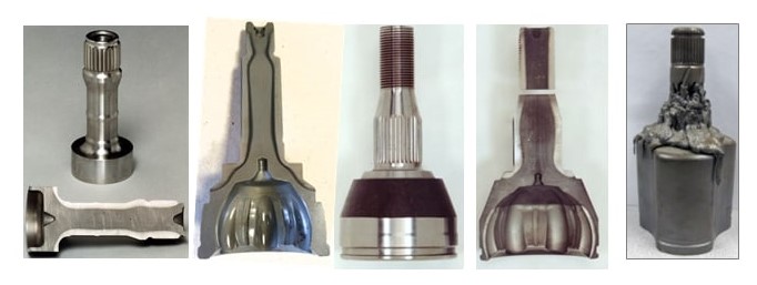
An appropriate inductor design with a closely controlled and monitored rotation speed will produce a hardness pattern with minimum circumferential and longitudinal temperature deviations, which will result in sufficiently uniform hardness patterns (Figure 5, left four images). Failure to ensure proper rotation as well as the use of worn centers (lacking grabbing force resulting in slippage and excessive part wobbling) could lead to an unacceptable heat non-uniformity, severe local overheating, and even melting (Figure 5, right). Manufacturers of induction equipment such as Inductoheat have developed various proprietary tools, holders, fixtures, and monitoring devices to ensure proper rotation and high quality of single-shot hardened parts.
Figure 5. Inductor design with closely controlled rotation speed will produce a hardness pattern with minimum circumferential temperature deviations (left four images). Failure to ensure proper rotation speed as well as the use of worn centers (lacking grabbing force resulting in slippage) could lead to unacceptable heat non-uniformity and can even cause a localized melting (right image).
The next installment of this column, "Dr. Valery Rudnev on . . . ", will continue the discussion of design features of induction single-shot hardening systems.
During the day-to-day operation of heat treat departments, many habits are formed and procedures followed that sometimes are done simply because that’s the way they’ve always been done. One of the great benefits of having a community of heat treaters is to challenge those habits and look at new ways of doing things. Heat TreatToday’s101 Heat TreatTips, tips and tricks that come from some of the industry’s foremost experts, were initially published in the FNA 2018 Special Print Edition, as a way to make the benefits of that community available to as many people as possible. This special edition is available in a digital format here.
Today we continue an intermittent series of posts drawn from the 101 tips. The tips for this post can be found in the FNA edition under Hardness Testing, CQI-9 Compliance, and Hardening/Tempering.
Heat TreatTip #22
Properly preparing a hardness sample can save time and money.
Inspection Mistakes That Cost
Rockwell hardness testing requires adherence to strict procedures for accurate results. Try this exercise to prove the importance of proper test procedures.
A certified Rc 54.3 +/- 1 test block was tested three times and the average of the readings was Rc 54 utilizing a flat anvil. Water was put on the anvil under the test block and the next three readings averaged Rc 52.1.
Why is it so important that samples are clean, dry, and properly prepared?
If your process test samples are actually one point above the high spec limit but you are reading two points lower, you will ship hard parts that your customer can reject.
If your process test samples are one point above the low spec limit but you are reading two points lower, you may reprocess parts that are actually within specification.
It is imperative that your personnel are trained in proper sample preparation and hardness testing procedures to maximize your quality results and minimize reprocessing.
Whether you need to meet rigid CQI-9 standards or not, what are the top 3, nay 4 best practices that nearly every in-house heat treat department ought to follow to make sure their pyrometer stuff is together?
Daily furnace atmosphere checks. Use an alternative method to verify your controls and sensors are operating properly and that there are no issue with your furnace or furnace gases.
Daily endothermic generator checks. Using an alternate method to verify your control parameter (dew point typically) or the gas composition is accurate will alleviate furnace control issues caused by bad endothermic gas.
Verify/validate your heat treat process every 2 hours OR make sure process deviations are automatically alarmed. this is a solid practice to ensure your controls and processes are running properly. This practice can help ensure that parts are being heat treated to the proper specification intended.
Conduct periodic system accuracy tests (SATs) per pre-defined timelines in CQI-9. Good pyrometry practices are an essential part of heat treatment. Because of the importance of temperature in heat treatment, ensure timeliness of all pyrometry practices addressing thermocouple usages, system accuracy tests, calibrations, and temperature uniformity surveys.
Control of Back Tempering With Induction Heat Treating
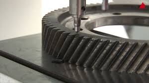
Induction heat treating is a selective hardening process. When hardening an induction path close to an area that had previously hardened, the heat from the hardening the second path tempers back the area that was previously hardened. This is a particularly common issue when tooth by tooth hardening of small gear teeth. Back tempering will reduce the hardness on the adjacent area and this effect may range from a few to over 10 HRC points.
Factors to Minimize Back Tempering
Process Issue
Questions to ask
Correct & repeatable placement of quenches
Can quench position be verified and set up repeatedly in the same position?
Verification of quench flow
Is the quench flowing freely through the quench system? Are the quench holes blocked? Are the flowmeters reading accurately?
Integrity of the quench
Was the percentage polymer measured? Is the quench quality okay? Is the quench contaminated?
Inductor design
Is the inductor designed to minimize heat on the tip? Is the quench effectively cooling the part?
Retained heat
Is a skip tooth hardening pattern being used to minimize residual heat in the induction hardening zone? Is the scan speed appropriate?
This article continues the ongoing discussion on Equipment Selection for Induction Hardening by Dr. Valery Rudnev, FASM, IFHTSE Fellow. Six previous installments in Dr. Rudnev’s series on equipment selection addressed selected aspects of scan hardening and continuous/progressive hardening systems. This post continues a discussion on equipment selection for induction hardening focusing on single-shot hardening systems.
The first part on equipment selection for continuous and progressive hardening is here. The second part in this series on equipment selection for single-shot hardening is here; the third part is here. To see the earlier articles in the Induction Hardening series at Heat TreatTodayas well as other news about Dr. Rudnev, click here. This installment continues a discussion on equipment selection for continuous and progressive hardening applications.
Why Single-Shot Hardening?
With the single-shot method, neither the workpiece (cylinder shaft, for example) nor the coil moves linearly relative to each other; the part typically rotates instead.¹ The entire region that is to be hardened is heated all at once rather than only a short distance, as is done with scan hardening.
With conventional scan hardening of cylindrical parts, induced eddy currents flow circumferentially. In contrast, a single-shot inductor induces eddy currents that primarily flow along the length of the part. An exception to this rule would be the half-moon regions (also called the crossover or bridge sections) of a single-shot inductor, where eddy current flow is circumferential.
Normally the single-shot method is better suited for hardening stepped parts where a relatively short (1.5–2 in. [38–50mm] long heated area is commonly minimum) or moderate length area is to be heat treated. This method is also better suited to cylindrical parts having axial symmetry and complex geometry including various diameters.
When scanning these types of parts, improper austenitization of certain areas may occur due to localized electromagnetic field distortion, for example. Insufficient quenching due to the deflection of quench flow not allowing it to properly impinge on the surface in various diameter regions may also occur. Both factors are considered undesirable and can cause low hardness, spotted hardness, or even cracking. For example, the use of scan hardening on stepped shafts with large shoulders, multiple and sizable diameter changes, and other geometrical irregularities and discontinuities (including fillets, flanges, undercuts, grooves, etc.) may produce severely non-uniform hardened patterns. In cases like this, a scan hardening inductor or progressive/continuous hardening system would be designed around the largest diameter that would have sufficient clearance for safe part processing.¹ However, variations in the shaft’s diameter, to a significant extent, will result in a corresponding substantial deviation in the workpiece-to-coil coupling in different sections of the shaft, potentially causing irregular austenization.
Besides that, sharp corners have a distinct tendency to overheat owing to the buildup of eddy currents, in particular when medium and high frequencies are used. The electromagnetic end and edge effects may also cause the shoulders to severely overheat while the smaller-diameter area near the shoulder (including undercuts and fillets) may have noticeable heat deficit. These factors may produce a hardness pattern that might grossly exceed the required minimum and maximum case depth range, making it unacceptable. Single-shot hardening is usually a better choice in such applications. As an example, Figure 1 shows some examples of components for which single-shot hardening would be a preferable method of heat treating.
Examples of components for which a single-shot hardening would be a preferable method of heat treating. (Courtesy of Inductoheat Inc., an Inductotherm Group company)
In some not so frequent cases, when hardening larger parts, there are advantages to the single-shot method over the scanning method, such as the reduction of shape/size distortion, enhanced metallurgical quality, and increased production rate.
Single-shot hardening may also be the preferred choice when shorter heat times/high production rates are desired. For example, in some applications, the time of heating for single-shot hardening can be as short as 2 s, though 4 to 8 s is more typical.
However, the single-shot method has some limitations as well. One of them is cost. Single-shot inductors are typically more expensive to fabricate compared to the coils used for scanning. This is because the single-shot inductor, to some degree, must follow the contour of the entire region required to be heated. Additionally, a single-shot inductor is usually able to harden only one specific part configuration, whereas a coil used for scanning may be able to harden a family of parts.
Besides that, in some case hardening applications using a scanning method, it is possible to apply certain pre-programmed pressure/force on a workpiece during heat treating. This allows distortion to be controlled. Single-shot hardening might also permit applying this technique but there might be some limitations.
Design Features of Single-Shot Inductors
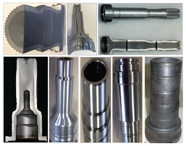
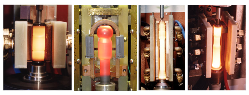
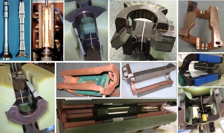
Single-shot inductors are made of tubing, either 3-D printed or CNC-machined from solid copper to conform to the area of the part to be heated. This type of inductor requires the most care in fabrication because it usually has an intricate design and operates at high power densities, and the workpiece’s positioning is critical with respect to the coil copper profiling. Figure 2 shows several examples of induction heating of different components using single-shot inductors.
Several examples of induction heating of different components using single-shot inductors. (Courtesy of Inductoheat Inc., an Inductotherm Group company)
In order to provide the required temperature distribution before quenching, heat is sometimes applied in several short bursts (pulse heating) with a timed delay/soaking between them to allow for thermal conduction toward the areas that might be difficult to heat.
Single-shot inductors typically require higher power levels than used in scan hardening because the entire area of the workpiece that needs to be hardened is austenitized at once. This is the reason why single-shot hardening normally requires having a noticeably larger power supply compared to scan hardening, resulting in increased capital cost of power source. Additionally, the increased power usage and power densities combined with complex geometry can reduce the life of the inductor. For this reason, single-shot inductors often have shorter lives than scan inductors.
It is always important to keep in mind that, electrically speaking, the inductor is typically considered the weakest link in an induction system. For this reason, most single-shot inductors have separate coil-cooling and part-quenching circuits. The inductor will fail if power is increased to the point at which the water cannot adequately cool it. Additional cooling passages may be needed with high-power density, single-shot inductors. A high-pressure booster pump is also frequently required.
The next several installments of Dr. Valery Rudnev on . . . will continue the discussion on design features of single-shot inductors and equipment selection.
During the day-to-day operation of heat treat departments, many habits are formed and procedures followed that sometimes are done simply because that’s the way they’ve always been done. One of the great benefits of having a community of heat treaters is to challenge those habits and look at new ways of doing things. Heat TreatToday‘s 101 Heat TreatTips, tips and tricks that come from some of the industry’s foremost experts, were initially published in the FNA 2018 Special Print Edition, as a way to make the benefits of that community available to as many people as possible. This special edition is available in a digital format here.
Today we continue an intermittent series of posts drawn from the 101 tips. The tips for this post come from a variety of categories but all generally address safety or cost-saving ideas.
Dr. Valery Rudnev, FASM, Fellow of IFHTSE, Professor Induction, Director Science & Technology, Inductoheat Inc., An Inductotherm Group company
Heat TreatTip #2
Avoid axle shaft cracks after induction tempering
Situation: In induction scan hardening of axle shafts, there was NO cracking occurred after scan hardening (case depth varies from 5 mm to 8 mm). Cracks appeared in the spline region after induction tempering.
Solution: Most likely, the cause of this problem is associated with a reversal of residual stress distribution during induction tempering. Reduce coil power for tempering and increase time of induction tempering. Multi-pulse induction tempering applying lower power density might also help. As an alternative, instead of modifying temper cycle, you can also try to reduce quench severity by increasing the temperature of the quenchant and/or its concentration.
When designing a vacuum furnace installation with a closed loop water system, elevate the tank and pump about 9 feet, then cage the space underneath for thermocouple storage, spares, and tools. Saves shop floor space.
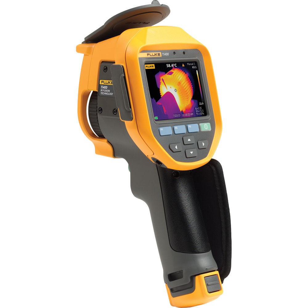
IR cameras have come way down in price—for a thousand dollars, you can have x-ray vision and see furnace insulation problems before they cause major problems—also a great diagnostic tool for motors, circuit breakers, etc. (And you can spot deer in the dark!)
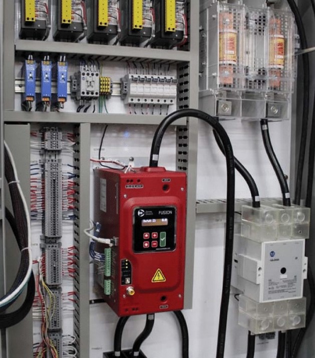
When SCRs are involved in the design of a new piece of equipment, questions arise. Control Concepts Inc of Chanhassen, MN, offers a 20-point design checklist to help engineers who don’t specialize in power controllers. Good reading. Search for “design checklist” at the website.
Before you specify a heat treatment, stop and consider your options. Rather than reusing an old specification, ask the design engineer to determine the stress profile, and base the hardness or case depth on real stress data. Is this complicated? Maybe. But especially for carburizing, why pay for more depth than you need, and why take the risk of inadequate strength? The 21st century is here. We have ways to help with the math. Let’s move beyond guess and test engineering methodology.
LEAX Group, a Swedish manufacturer of advanced components and subsystems for automotive, commercial vehicles, mining, construction, and general industry sectors, has installed a low pressure carburizing (LPC) furnace at their Brinkmann, Germany, facility (LEAX Brinkmann GmbH) to boost the company’s heat treatment processing capabilities. The extensive installation takes about two months and the first hot load is scheduled for December. Along with the addition of a new induction machine at their Falköping, Sweden, facility, this new LPC furnace serves as the centerpiece of the massive MBS project.
LEAX, which is based in Köping, Sweden, operates heat treatment shops in seven of their twelve production sites, including Latvia, Germany, Hungary, Brazil, and China, and focuses on induction hardening and processing and refining approximately 300,000 parts per year. This added LPC hardening furnace brings a process to LEAX’s manufacturing process that has been a mainstay in the automotive industry. The full transition to the MBS project will take up to two years, but “we [will] switch hardening from the older oven to the new,” said Anders G. Larsson, COO/Heat Treatment for LEAX Brinkmann GmbH.
Combining the ancient craft of blacksmithing with heat treating processes, artisan Robert (Mac) McPherson obtained the finish he wanted for a suit of armor designed after a late 15th-century statue of the patron saint of firefighters. The suit was fashioned with 125 hand-formed, then hardened and tempered metal plates.
ThermTech, based in Waukesha, WI, recently added a batch integral quench furnace to their atmosphere heat-treat furnace line. The expansion is in response to an increase in demand for carburizing, carbonitriding, and neutral hardening services from their oil & gas and heavy equipment industry clients. ThermTech acquired the ATLAS furnace from Ipsen USA, adding to existing atmosphere furnace and ancillary equipment already in operation.
by Stephen Thompson – President – Super Systems, Inc.
There are several key components in all atmosphere control systems. When a difficulty arises, it is important to identify the cause with minimum effort and expended time. The procedure that follows is designed to aid in that process.
INTRODUCTION
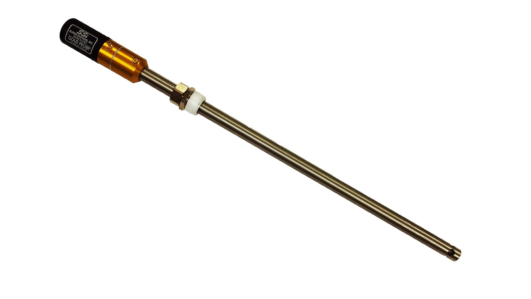
The starting point for any troubleshooting procedure is to properly identify the symptom that necessitates it. The cause of the symptom can often be elicited by answering some preliminary questions. Is this a startup problem, or has the system been operating under control? If this is a startup problem, it is necessary to establish that all system components have been properly connected and configured for the application. If the system has been operating properly and there has been either a gradual or sudden change in the control performance, it may conceivably be a problem with the probe. In order to establish the correct performance of the carbon sensor, resist the temptation to remove the sensor from the furnace. All of the tests outlined here must be done while the sensor is located in the furnace, at temperature, and exposed to a reducing atmosphere. This procedure can be performed on the SSi Gold Probe and on most other manufacturers’ sensors. We strongly recommend that you call us at 800-666-4330 before you remove the probe.
NOTE: IF YOU HAVE ALREADY REPLACED THE PROBE AND THE PROBLEM PERSISTS…..THE PROBE MAY NOT BE THE PROBLEM!
PROCEDURE
Does a shim stock analysis, a 3-gas analysis (SSi PGA3000) or a dew point analysis (SSi DP2000) verify the indicated value from the probe? If the values are close to the same, the problem is not likely the Gold Probe. If the values are not similar, continue with the following steps:
Verify that both mV and t/c cables between the sensor and the controller are clean and connected firmly to the Gold Probe and controller terminals. Verify polarity.
Verify that the reference air supply is connected to the reference air fitting. This will be the fitting closest to you when you face the probe. It has been found that on occasion the reference air has been connected in error to the burn off fitting, causing low readings.
Check that the reference air is flowing. Disconnect the air supply at the probe and submerge it in a cup of water. Bubbles verify the flow.
Verify that no air is flowing into the burn off fitting by submerging the burn off tubing in a cup of water. (Flow can occur if the burn off air pump is subject to external vibration.)
Leak test- this test can detect a cracked or broken substrate in your Gold Probe. Verify that reference air is flowing at 0.5 to 2.0 scfh. Turn off the reference air for one minute and read the Gold Probe output millivolts. Turn the reference air back on and note the change in mV. It should not display more than a 5 mV increase.
Is the controller COF set to the proper value? This factor is referred to by other descriptions such as Process Factor, Furnace Factor, CO Factor, Circulation Factor, Calibration Factor, etc. The factor may require adjustment to eliminate any offset or discrepancy between the indicated carbon potential and the actual achieved result in the work pieces or shim stock.
Do the sensor temperature and MV output as measured by an independent digital calibrator agree with the indicated values on the controller with one sensor and one t/c lead disconnected? If not, there is most likely a controller calibration problem or a cable problem.
Does the Gold Probe mV signal return to within 1mV of it’s original value in 1 minute as measured by a digital VOM after it has been shorted for 5 seconds? If it does not, go to step 10.
Probe impedance (resistance) test-this is one of several electrical tests that determine the electrical integrity and reliability of the Gold Probe. Some contemporary controllers can perform it. If yours does not, conduct this simple test: at process temperature, disconnect the controller cable at the Gold Probe mV output and measure the mV value with a VOM. Then shunt the signal with a 100 kilohm resistor. After 10 seconds, read the new mV value, divide the original value by the new value, subtract 1 from the result and multiply by the value of the shunt resistor (=100K). The calculated value is the sensor resistance in kilohms, which should be less than 25 kilohms.
If the problem is not corrected by probe and/or furnace burnout as described in the Gold Probe Manual and your system manual, and the problem is a faulty probe, contact SSi at (800)666-4330 and describe your problem to our technician. You may then request a Returned Material Authorization for repair or replacement of your Gold Probe.
WARNING- even though you suspect a faulty sensor, DO NOT remove your Gold Probe from a hot furnace at a rate faster than 2 inches per minute. Cool the sensor on an insulating medium to avoid thermal shock. This will prevent damage that is expensive to repair.
Author information:
Stephen Thompson
Super Systems Inc.
7205 Edington Drive, Cincinnati, OH 45249
Phone: 513-772-0060
Fax: 513-772-9466 www.supersystems.com
“While LPC with electric heating and HPGQ have won over many auto OEMs, oil LPC, oil-marquenching, and heating with natural gas can offer an effective, lower cost alternative for neutral hardening and carburizing.”


![Figure 2. Computer-modeled EMF distribution in the transverse cross-section of a bare inductor (left) compared to an inductor with U-shaped flux concentrator (right). Note: the scale of magnetic field intensity on both images is different [1].](https://heattreattoday.com/wp-content/uploads/2019/08/Rudnev-Part-2-Fig-2.jpg)
![Figure 3. Sketch of single-shot induction hardening of an axle shaft. Note: The right half of this induction system is computer-modeled in Fig. 4 [3].](https://heattreattoday.com/wp-content/uploads/2019/08/Rudnev-Part-2-Fig-3.jpg)
![Figure 4. Results of numerical simulation of heating an axle shaft by using a single-shot inductor [3].](https://heattreattoday.com/wp-content/uploads/2019/08/Rudnev-Part-2-Fig-4.jpg)