Vacuum Brazing for Automotive Applications

Alessandro Fiorese, R&D Chief Engineer with TAV Vacuum Furnaces SPA, introduces the vacuum brazing process for automotive applications. For more articles, tips, and news related to heat treatment for automotive applications, keep an eye out for Heat Treat Today’s special print/digital issue Automotive Heat Treating, due in June 2019.
Introduction
Brazing is a heat treatment process in which metallic parts are joined together through a metallic filler with a melting temperature lower than the melting point of the joined parts. The filler metal can be used as a wire, a thin plate, or a paste depending upon the final application we are considering.
To obtain a good welding in terms of mechanical properties and corrosion resistance, it’s necessary to minimize contamination and impurities in the joined zone. Vacuum brazing processing provides a way to reach a high cleaning level of atmosphere during the brazing heat treatment.
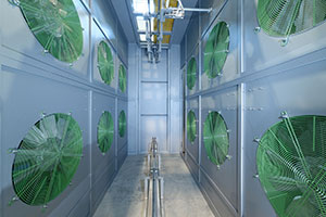
The brazing treatment is particularly useful to produce complex shape parts with a lot of joining points per unit of area. Typical brazing applications are oil or water heat exchangers in the civil and automotive fields such as the ones represented below.
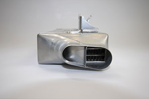
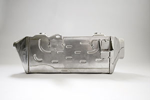
The high-performance aluminum heat exchangers manufacturing is growing particularly in the automotive field. In this context, AA 3xxx and 4xxx are commonly used materials for parts and filler material respectively because these materials have a very low specific weight and a very high thermal conductivity level.
As indicated before, one of the cleanest brazing atmospheres is vacuum. For this reason, in the following discussion, we will analyze in detail the complete characteristics of a semi-automatic TAV vacuum brazing furnace for automotive applications.
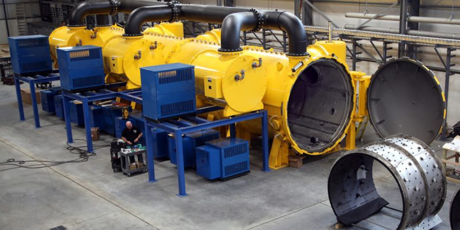
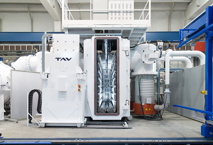
Vacuum Brazing Furnace
The entire furnace is composed of three different stations:
- the heating furnace;
- the loading station;
- the cooling station.
Heating Furnace
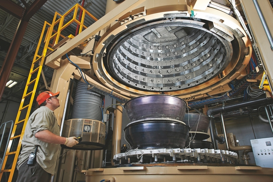
Furnace Vessel
The vessel separates the inner part of the furnace where the hot chamber is placed from the outside environment. The vessel develops along a horizontal axis, it has an elliptical design and it is provided with two flat doors (front and rear). Both doors are hinged and can be opened manually. The front door has an automatically sliding entrance for loading-unloading the furnace.
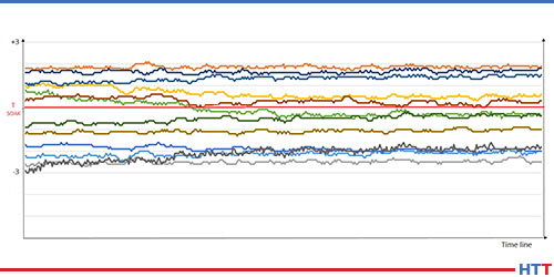
Hot Chamber
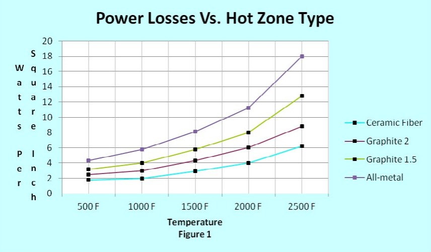
The thermal chamber has a rectangular section 71 (H) x 18 (W) x 144 (L) inches (180 x 45x 365 cm), and it is constituted by steel panels with nickel-chrome resistors. There are 23 independent hot zones that make the chamber temperature very well-controlled. The temperature uniformity requested for this vacuum furnace is ± 37°F (± 3°C) from the set temperature. In the following picture, the ± 37°F Temperature Uniformity Survey (TUS) chart is shown.
Vacuum System
The vacuum system has three pumping groups, two with a rotary piston pump, a roots pump, and an oil diffusion pump. The third pumping group has a mechanical pump, a roots pump, and a cryo-trap in order to condensate humidity and impurities released during the entire process. The ultimate reachable vacuum without the load is 10-6 mbar (range).
Loading Station
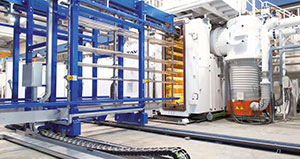
Loading Baskets
To carry out the brazing heat treatment in a correct way, a specific steel shelved fixtures hold the heat exchangers parts all together with the filler material. For each brazing process, a load from 1984 up to 4850lbs (900 up to 2200kg) can be heat treated at the same time. For gaining a semi-automatic heat treatment process, there is a parking station that can be used as a buffer for the heating furnace.
Cooling Station
At the end of the brazing heat treatment, the load is automatically transferred into a separate cooling chamber where the brazed parts are cooled down by forced recirculation of air.
Heat Treatment
Before reaching the brazing temperature, the load is maintained at a lower temperature for a period of time to remove the working oil plate from the heat exchangers. During this maintenance time, a variation between high vacuum and partial pressure of N2 is observed.
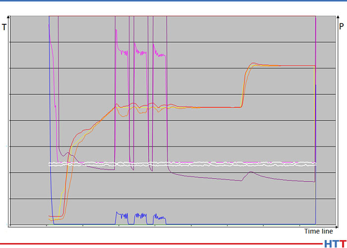
After the brazing step, the furnace reaches high nitrogen static partial pressure, starting the cooling phase. This step is considered complete when the furnace injects air up to reach the atmospheric pressure as total pressure. At this time, the front door opens automatically, and the loading track extracts the charge from the furnace.
Vacuum Brazing for Automotive Applications Read More »